EP1174673A2 - Wärmeaustauschsmodul, insbesondere für Kraftfahrzeug, und Verfahren zu dessen Verwendung - Google Patents
Wärmeaustauschsmodul, insbesondere für Kraftfahrzeug, und Verfahren zu dessen Verwendung Download PDFInfo
- Publication number
- EP1174673A2 EP1174673A2 EP01115796A EP01115796A EP1174673A2 EP 1174673 A2 EP1174673 A2 EP 1174673A2 EP 01115796 A EP01115796 A EP 01115796A EP 01115796 A EP01115796 A EP 01115796A EP 1174673 A2 EP1174673 A2 EP 1174673A2
- Authority
- EP
- European Patent Office
- Prior art keywords
- tubes
- fins
- exchangers
- elongated
- cutouts
- Prior art date
- Legal status (The legal status is an assumption and is not a legal conclusion. Google has not performed a legal analysis and makes no representation as to the accuracy of the status listed.)
- Granted
Links
Images


Classifications
-
- F—MECHANICAL ENGINEERING; LIGHTING; HEATING; WEAPONS; BLASTING
- F28—HEAT EXCHANGE IN GENERAL
- F28F—DETAILS OF HEAT-EXCHANGE AND HEAT-TRANSFER APPARATUS, OF GENERAL APPLICATION
- F28F1/00—Tubular elements; Assemblies of tubular elements
- F28F1/10—Tubular elements and assemblies thereof with means for increasing heat-transfer area, e.g. with fins, with projections, with recesses
- F28F1/12—Tubular elements and assemblies thereof with means for increasing heat-transfer area, e.g. with fins, with projections, with recesses the means being only outside the tubular element
- F28F1/24—Tubular elements and assemblies thereof with means for increasing heat-transfer area, e.g. with fins, with projections, with recesses the means being only outside the tubular element and extending transversely
- F28F1/32—Tubular elements and assemblies thereof with means for increasing heat-transfer area, e.g. with fins, with projections, with recesses the means being only outside the tubular element and extending transversely the means having portions engaging further tubular elements
-
- F—MECHANICAL ENGINEERING; LIGHTING; HEATING; WEAPONS; BLASTING
- F28—HEAT EXCHANGE IN GENERAL
- F28D—HEAT-EXCHANGE APPARATUS, NOT PROVIDED FOR IN ANOTHER SUBCLASS, IN WHICH THE HEAT-EXCHANGE MEDIA DO NOT COME INTO DIRECT CONTACT
- F28D1/00—Heat-exchange apparatus having stationary conduit assemblies for one heat-exchange medium only, the media being in contact with different sides of the conduit wall, in which the other heat-exchange medium is a large body of fluid, e.g. domestic or motor car radiators
- F28D1/02—Heat-exchange apparatus having stationary conduit assemblies for one heat-exchange medium only, the media being in contact with different sides of the conduit wall, in which the other heat-exchange medium is a large body of fluid, e.g. domestic or motor car radiators with heat-exchange conduits immersed in the body of fluid
- F28D1/04—Heat-exchange apparatus having stationary conduit assemblies for one heat-exchange medium only, the media being in contact with different sides of the conduit wall, in which the other heat-exchange medium is a large body of fluid, e.g. domestic or motor car radiators with heat-exchange conduits immersed in the body of fluid with tubular conduits
- F28D1/0408—Multi-circuit heat exchangers, e.g. integrating different heat exchange sections in the same unit or heat exchangers for more than two fluids
- F28D1/0426—Multi-circuit heat exchangers, e.g. integrating different heat exchange sections in the same unit or heat exchangers for more than two fluids with units having particular arrangement relative to the large body of fluid, e.g. with interleaved units or with adjacent heat exchange units in common air flow or with units extending at an angle to each other or with units arranged around a central element
- F28D1/0435—Combination of units extending one behind the other
-
- F—MECHANICAL ENGINEERING; LIGHTING; HEATING; WEAPONS; BLASTING
- F28—HEAT EXCHANGE IN GENERAL
- F28D—HEAT-EXCHANGE APPARATUS, NOT PROVIDED FOR IN ANOTHER SUBCLASS, IN WHICH THE HEAT-EXCHANGE MEDIA DO NOT COME INTO DIRECT CONTACT
- F28D21/00—Heat-exchange apparatus not covered by any of the groups F28D1/00 - F28D20/00
- F28D2021/0019—Other heat exchangers for particular applications; Heat exchange systems not otherwise provided for
- F28D2021/008—Other heat exchangers for particular applications; Heat exchange systems not otherwise provided for for vehicles
- F28D2021/0084—Condensers
-
- F—MECHANICAL ENGINEERING; LIGHTING; HEATING; WEAPONS; BLASTING
- F28—HEAT EXCHANGE IN GENERAL
- F28D—HEAT-EXCHANGE APPARATUS, NOT PROVIDED FOR IN ANOTHER SUBCLASS, IN WHICH THE HEAT-EXCHANGE MEDIA DO NOT COME INTO DIRECT CONTACT
- F28D21/00—Heat-exchange apparatus not covered by any of the groups F28D1/00 - F28D20/00
- F28D2021/0019—Other heat exchangers for particular applications; Heat exchange systems not otherwise provided for
- F28D2021/008—Other heat exchangers for particular applications; Heat exchange systems not otherwise provided for for vehicles
- F28D2021/0091—Radiators
- F28D2021/0094—Radiators for recooling the engine coolant
-
- F—MECHANICAL ENGINEERING; LIGHTING; HEATING; WEAPONS; BLASTING
- F28—HEAT EXCHANGE IN GENERAL
- F28F—DETAILS OF HEAT-EXCHANGE AND HEAT-TRANSFER APPARATUS, OF GENERAL APPLICATION
- F28F21/00—Constructions of heat-exchange apparatus characterised by the selection of particular materials
- F28F21/06—Constructions of heat-exchange apparatus characterised by the selection of particular materials of plastics material
- F28F21/067—Details
-
- F—MECHANICAL ENGINEERING; LIGHTING; HEATING; WEAPONS; BLASTING
- F28—HEAT EXCHANGE IN GENERAL
- F28F—DETAILS OF HEAT-EXCHANGE AND HEAT-TRANSFER APPARATUS, OF GENERAL APPLICATION
- F28F2215/00—Fins
- F28F2215/02—Arrangements of fins common to different heat exchange sections, the fins being in contact with different heat exchange media
-
- F—MECHANICAL ENGINEERING; LIGHTING; HEATING; WEAPONS; BLASTING
- F28—HEAT EXCHANGE IN GENERAL
- F28F—DETAILS OF HEAT-EXCHANGE AND HEAT-TRANSFER APPARATUS, OF GENERAL APPLICATION
- F28F2215/00—Fins
- F28F2215/12—Fins with U-shaped slots for laterally inserting conduits
Definitions
- the invention relates to a heat exchange module, in particular for motor vehicles, consisting of several exchangers having common fins.
- a module for exchanging heat comprising at least two heat exchangers, each exchanger consisting of a bundle interposed between two manifolds, the beam being formed of tubes of circulation of fluid connected to the manifolds and which pass through cooling fins common to at least two module exchangers.
- Motor vehicle heat exchangers are generally in the form of a bundle of circulation of fluid and heat exchange fins with the external environment.
- the beam is interposed between two boxes manifolds that distribute the fluid in the tubes of circulation.
- the exchanger includes a single manifold divided into an inlet section and a outlet section.
- a main exchanger such as a motor vehicle engine cooling radiator
- secondary exchangers in order to constitute a assembly, also called module, ready to be installed in the vehicle, the fins of the module being common to the different exchangers.
- the secondary exchanger is most often made up an engine charge air cooler, a air conditioning condenser or oil cooler.
- the exchangers are assembled in a single brazing operation.
- the fins consist of corrugated interleaves arranged between the tubes and parallel to them.
- the component parts of the exchanger are assembled exclusively by mechanical means such as crimping. This type of exchanger has fine and flat fins, arranged perpendicular to the tubes and crossed by these last.
- Mechanically assembled exchangers have several benefits. They are compact, they offer ease of mounting the manifolds, the distance between the ends of the tubes being precise. Their fins being thinner than those of brazed exchangers, they are more numerous and allow a better heat exchange. However, they present the disadvantage of requiring assembly operations costly in time and tools. In particular, the assembly secondary exchanger (s) on the main exchanger must be obtained by special mechanical means which harm the compactness of the module.
- the present invention relates to a module for exchanging heat which, while retaining the specific advantages of mechanically assembled exchangers, provides ease assembly of the exchangers between them and makes it possible to produce a compact heat exchange module.
- the tubes and the fins are joined by brazing and that the fins have the shape of an elongated rectangle having two elongated sides and two short sides, the fins comprising, on at least one of the elongated sides, cutouts receiving tubes in which the circulation tubes at least one of the exchangers are introduced.
- the assembly of the module is particularly simplified in since the tubes can be slid sideways into the receiving cutouts of the tubes of the fins, before being secured to these fins by brazing.
- the invention preferably applies to the exchange modules of heat comprising metal manifolds, particularly aluminum.
- the plate to tubes and the cover being metallic, the cover, the plate tubes and the bundle are assembled by soldering into one surgery.
- This alternative embodiment therefore requires a minimum assembly operations.
- the invention also applies to the case where the beam only is brazed.
- the tube plates are conventionally fixed to the tubes by flaring of the ends of these.
- the cover of the manifold made for example of plastic will be assembled alone mechanically, for example by crimping tabs on the box collecting.
- This variant has the advantage of deleting a number of mechanical plate assembly operations tubes on the ends of the bundle tubes.
- the tube receiving cutouts only exist on one of the two elongated sides of the fins.
- the heat exchange module since the heat exchange module has at least two exchangers, two or more than two tubes are successively introduced into each of the cutouts reception practiced in the fin. Cutting can thus contain two, three or more tubes.
- the fin includes tube receiving cutouts on both sides elongate.
- the exchanger tubes are distributed on both elongated sides of the fins.
- the tubes of an exchanger are introduced into the receiving cutouts tubes from one of the elongated sides, while the tubes from circulation of fluid are introduced into the cutouts of receiving tubes on the other elongated side.
- the module heat exchanger has more than two exchangers, per example three, we will introduce the tubes of two exchangers in the tube receiving cutouts on one of the elongated sides, and the tubes of the third exchanger in the cutouts of receiving tubes on the other elongated side.
- the tube receiving cutouts may have a constant width over their entire length.
- the cutouts for receiving tubes have a widening stepped profile from the bottom of the cut to the entrance of the cut.
- This embodiment is particularly suited to the case where the exchangers have fluid circulation tubes of thicknesses different.
- the stepped profile of the receiving cutout tubes allows to adapt the width of the cut to the thickness tubes of each exchanger.
- each cutout for receiving a tube comprises a thermal insulation notch located between the tubes of the exchangers.
- This notch is intended to avoid, in any wherever possible, establishing a thermal bridge between the part of the fins corresponding to an exchanger and the part fins corresponding to the adjacent exchanger.
- the fins and / or the tubes are covered with a solder plating.
- the short sides of the fins are folded down and joined to the bundle by brazing.
- the invention further relates to a method of manufacturing a heat exchange module comprising at least two exchangers heat, each exchanger consisting of a bundle interposed between two manifolds, the beam being formed of fluid circulation tubes connected to the boxes manifolds, and which passes through cooling fins common to the module exchangers, the fins having the shaped like an elongated rectangle having two elongated sides and two short sides.
- the cover, the tube plate and the bundle are assembled by brazing into a single operation. If all tube plates and all covers are metallic, for example aluminum, the module is assembled in a single operation by soldering and all mechanical assembly operations are eliminated.
- the tube plate and harness can be assembled by soldering in one operation.
- the manifold is then mechanically assembled in a later operation.
- the heat exchange module shown in Figure 1 is composed of a radiator 1 for cooling an engine motor vehicle and an air conditioning condenser 2, these two interchanges being generally planar.
- the radiator 1 consists in a known manner of a beam of vertical fluid circulation tubes 5 mounted between two manifolds 6 (only one box has been shown), the manifolds 6 being arranged along two sides parallel to the bundle of tubes and fitted with tubes 8 inlet and outlet of the coolant.
- the condenser 2 also consists of a bundle of tubes vertical fluid circulation 10 mounted between two boxes manifolds 12 (only one box has been shown), the boxes manifolds being arranged along two parallel sides of the bundle and fitted with inlet and outlet pipes from the refrigerant (not shown).
- Fins 14 common to exchangers 1 and 2 are mounted from conventionally on the tubes 5 of the exchanger 1 and the tubes 10 of the exchanger 2.
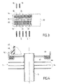
- Figure 3 shows, in plan view, the shape of a elongated rectangle (see figure 3) comprising a first and a second elongated sides 16, 18 and two short sides 20.
- the cutouts 22 and 24 have a shape corresponding to that of the tubes. Their width is designed to in such a way that the tubes can be introduced therein just sliding.
- the pitch of cuts 22 and 24 is equal to that of tubes 5 and 10.
- the fin 14 is separated into two zones heat exchange by two series of elongated perforations 26 intended to avoid as far as possible the establishment of a thermal bridge between the part of the fins 14 corresponding to exchanger 1 and the part of the fins 14 corresponding to exchanger 2.
- the manifold 6 of the exchanger 1 ( Figure 1) includes a first part 28 and a second part 30, each formed at from a metal sheet, advantageously aluminum, which is shaped by conventional cutting operations and stamping.
- the first part 28 has a bottom 32 which is generally flat and elongated rectangular shape.
- This background 32 is intended to constitute the collecting plate, also called “plate to holes ", of the manifold 6.
- This bottom comprises for this purpose a plurality of spaced apart holes 34 of elongate shape for receive the tubes 5 of the exchanger 1 ( Figure 2).
- Part 30 further comprises two lateral sides 36 folded opposite which are generally planar and parallel to each other. These flanks 36 are connected substantially perpendicular to the bottom 32 by two fold lines which are parallel to each other.
- the tubing 8 is arranged in one of the lateral flanks 36.
- the second part 30 is obtained from a strip metallic of given width which has generators parallel. This strip can come to fit between the sides side 36 of the first part 28 to form a set ready to be soldered together with tubing 8.
- the manifold 12 of the exchanger 2 has the form general of an elongated cylinder provided with perforations (not visible in Figure 1) intended to receive the tubes 10 of the exchanger.
- the exchanger is assembled as follows. We assemble at share the manifolds of each of the two exchangers and the respective tubes of each of these exchangers.
- the fins are superimposed on each other in such a way that the cutouts 22 and 24 for receiving the tubes 5 and 10 are in line with one another.
- the tubes 5 of the exchanger 1 on the elongated side 16 fins 14 and the tubes 10 of the exchanger 2 on the elongated side 18 of the fins 14. All the parts of the exchanger having been thus assembled, the heat exchange module can be brazed in a single operation in a brazing furnace, so conventional.
- the tubes and / or the fins advantageously comprise a solder plating.
- the short sides 20 of the fins 14 are folded down and joined to the bundle by brazing.
- FIG. 4 a cross-sectional view of an alternative embodiment of the exchanger 1 forming part of a heat exchange module identical to that which has been described with reference to Figures 1 to 3.
- the exchanger includes a manifold 40 which is not metallic. It cannot therefore be assembled by soldering in a single operation to the rest of the exchange module heat.
- the collector plate 42 which is metal can be assembled by brazing to tubes 5 of exchanger 1.
- the plate with tubes 42 has a groove 44 into which is inserted a seal 46.
- a seal is produced so by applying the foot 48 of the cover 40 to the seal 46 and by crimping the cover 40 on the tube plate 42 by means of folded legs 50 forming part from the tube plate.
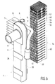
- FIG. 5 shows a partial perspective view a pad of fins for a heat exchange module according to a second embodiment of the invention.
- each fin 14 has two elongated sides 16, 18 and two short sides 20.
- the elongated sides 16 and 18 do not appear longer than the short sides 20 because the representation of the fin is partial for the sake of simplification. In reality, the fin has the shape of a very elongated rectangle.
- the fins 14 have on one of the elongated sides, the side 16 in the example, cutouts 22 intended for the reception of fluid circulation tubes of two exchangers forming part a heat exchange module.
- cutouts 22 are sufficiently elongated to accommodate simultaneously the tubes of the two exchangers.
- the width of the cutout 22 could be constant.
- the cutout 22 consists of a larger section 52 width and a section 54 of smaller width.
- the section 54 is located on the bottom side 60 of the cutout 22, while section 52 is located on the entrance side 62 of this last. In this way, the cut has a stepped profile which widens from the bottom 60 towards the entrance 62 of the cutting.
- the two sections 52 and 54 are separated from each other by a thermal insulation notch 56 intended to limit the heat transmission between section 52 and section 54.
- a thermal insulation notch 56 intended to limit the heat transmission between section 52 and section 54.
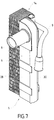
- FIG. 6 shows a partial perspective view a heat exchange module conforming to the second mode of realization of the invention prior to its assembly and, in FIG. 7, this same heat exchange module in position Assembly.
- the heat exchange module is consisting of two subsets.
- the first subset is consisting of two exchangers, namely a radiator 1 of cooling of a motor vehicle engine and a air conditioning condenser 2, these two exchangers being generally plans.
- the radiator 1 consists in a known manner of a beam of vertical fluid circulation tubes 5 mounted between two manifolds 6 (only one box has been shown), the manifolds 6 being arranged along two sides parallel to the bundle of tubes and fitted with tubes 8 inlet and outlet due to coolant.
- the manifold 6 of the exchanger 1 comprises a first part 28 and a second part 30, each formed from a metal sheet, preferably aluminum.
- the first part 28 has a bottom 32 which is generally flat and of elongated rectangular shape, intended to constitute the header plate which receives the tubes 5.
- the condenser 2 also consists of a bundle of tubes vertical fluid circulation 10 mounted between two boxes manifolds 12 (only one box has been shown), the boxes manifolds being arranged along two parallel sides of the bundle and fitted with inlet and outlet pipes 9 of the refrigerant.
- the second subset which constitutes the exchange module of heat is constituted by a stack of fins 14, all identical to each other. These fins have been described with reference to Figure 5.
- the two sub-assemblies are shown assembled to form the heat exchange module.
- the tubes 10 of the bundle of the condenser are thinner and shorter than the tubes 5 of the radiator heat exchange bundle 1. This is the reason for which the section 54 of the tube reception area 22, located on the bottom side 60 of this cut, is narrower and shorter than section 52 located on the side of entrance 62 of this cutout.
- the cutout 22 has a profile in bleachers widening from the bottom 60 of the cutout towards its entrance 62. This stepped profile makes it possible to adapt the shape exactly from there cut to the geometry of the tubes 5 and 10 of the two heat exchanger modules.
- the first subset i.e. exchangers 1 and 2 consisting of their manifold and bundle of tubes from each of them, is assembled separately by brazing, without the fins 14. Then the tubes 10 and 5 are introduced into the cutouts 22 of the fin block 14. The width of sections 52 and 54 is designed so that the tubes are forcibly inserted into the cutouts 22.
- the connection between tubes 5 and 10 of the heat exchange module and the fins 14 is thus of the mechanical type.
- this embodiment is susceptible of various variants. It is, for example, possible to solder only the tube plate 32 to the bundle tubes and to assemble mechanically the manifold 6 mechanically.
- the two exchangers 1 and 2 are assembled with the fin block 14 and the whole is brazed in a single operation in an oven.
- the thermal connection between the tubes 5 and 10 of the exchangers and the fins 14 is of the brazed type.
- the main advantage of a mechanical connection is the makes it possible to use bent tubes with channels. Indeed, for reasons of mechanical strength, the use of flat tubes without channels is prohibited in this type of embodiment. Control leaks on the exchangers can be achieved before mounting on the fins 14. The necessary flux residues brazing will be limited to tubes and boxes collector. It is also easier to remove the bridge between the two exchangers since the critical part is between the two rows of tubes and that, due to the space left free between these two rows of tubes in the cutout 22 for receiving the tubes, there is no material conductor between the two exchangers, except for the exchange surface formed by the shutters 57.
- plane fins such as the fins 14 allows the removal of the exchanger cheeks which are required in a heat exchanger have spacers wavy.
- FIG. 8 shows an alternative embodiment of the fins 14.
- the fins 14 comprise a tube receiving cutout 22 on the elongated side 16 and a tube receiving cutout 24 on the elongated side 18.
- the cutouts 22 are similar to the cutouts described on Figures 5 to 7. In other words, their length is expected to be in such a way that they are able to receive the tubes of two exchangers, for example a cooling radiator and an air conditioning condenser. They have a profile in bleachers which widens from the bottom 60 towards the entrance 62 of cuts. Sections 52 and 54, adapted to the reception of tubes of each of the two exchangers, are separated by a notch 56 for thermal insulation.
- the tube receiving cutout 24 provided on the sides elongated 18 fins 14 is similar to the cut 24 shown in Figures 1 to 4. In other words, it is designed to accommodate the tubes of a single heat exchanger. Thus, in total, the fins 14 shown in Figure 8 can receive the tubes of three exchangers.
- the module heat exchange can thus consist of three exchangers.
- the cuts receiving tubes can be provided to receive more of two tubes, for example three or more.
- a heat exchange module could include four exchangers, the tubes of two of these exchangers being introduced into the cutouts 22, while the tubes of the two other exchangers are introduced in the cutouts 24.
Landscapes
- Engineering & Computer Science (AREA)
- Physics & Mathematics (AREA)
- Thermal Sciences (AREA)
- Mechanical Engineering (AREA)
- General Engineering & Computer Science (AREA)
- Geometry (AREA)
- Heat-Exchange Devices With Radiators And Conduit Assemblies (AREA)
- Air-Conditioning For Vehicles (AREA)
Applications Claiming Priority (2)
| Application Number | Priority Date | Filing Date | Title |
|---|---|---|---|
| FR0009419A FR2812081B1 (fr) | 2000-07-18 | 2000-07-18 | Module d'echange de chaleur, notamment pour vehicule automobile, et procede de fabrication de ce module |
| FR0009419 | 2000-07-18 |
Publications (3)
| Publication Number | Publication Date |
|---|---|
| EP1174673A2 true EP1174673A2 (de) | 2002-01-23 |
| EP1174673A3 EP1174673A3 (de) | 2002-07-31 |
| EP1174673B1 EP1174673B1 (de) | 2007-01-31 |
Family
ID=8852647
Family Applications (1)
| Application Number | Title | Priority Date | Filing Date |
|---|---|---|---|
| EP01115796A Expired - Lifetime EP1174673B1 (de) | 2000-07-18 | 2001-07-11 | Wärmeaustauschsmodul, insbesondere für Kraftfahrzeug, und Verfahren zu dessen Verwendung |
Country Status (6)
| Country | Link |
|---|---|
| EP (1) | EP1174673B1 (de) |
| AT (1) | ATE353133T1 (de) |
| BR (1) | BR0102939A (de) |
| DE (1) | DE60126381T2 (de) |
| FR (1) | FR2812081B1 (de) |
| MX (1) | MXPA01007260A (de) |
Cited By (9)
| Publication number | Priority date | Publication date | Assignee | Title |
|---|---|---|---|---|
| JP2003262485A (ja) * | 2002-03-07 | 2003-09-19 | Mitsubishi Electric Corp | フィンチューブ型熱交換器、その製造方法及び冷凍空調装置 |
| FR2844586A1 (fr) * | 2002-09-12 | 2004-03-19 | Valeo Thermique Moteur Sa | Module d'echange de chaleur, en particulier pour vehicules automobiles, comportant des moyens de maintien des ailettes |
| FR2849173A1 (fr) * | 2002-12-19 | 2004-06-25 | Valeo Thermique Moteur Sa | Module d'echangeur de chaleur, notamment pour vehicule automobile, comportant une pluralite d'echangeurs de chaleur |
| FR2853052A1 (fr) * | 2003-03-31 | 2004-10-01 | Valeo Thermique Moteur Sa | Module d'echange de chaleur a fonctionnement optimise, notamment pour vehicule automobile |
| FR2856783A1 (fr) * | 2003-05-15 | 2004-12-31 | Valeo Thermique Moteur Sa | Echangeur de chaleur et module d'echange de chaleur comprenant un tel echangeur, ainsi que procede de fabrication d'un tel echangeur et d'un tel module |
| GB2375164B (en) * | 2001-05-04 | 2005-11-30 | Llanelli Radiators Ltd | Heat exchanger system |
| WO2006005594A1 (de) * | 2004-07-12 | 2006-01-19 | Behr Gmbh & Co. Kg | Wärmeübertrager, insbesondere für kraftfahrzeuge |
| FR2875591A1 (fr) * | 2004-09-17 | 2006-03-24 | Valeo Thermique Moteur Sas | Echangeur de chaleur a ailettes perfectionnees |
| FR3090838A1 (fr) * | 2018-12-19 | 2020-06-26 | Valeo Systemes Thermiques | Echangeur de chaleur pour véhicule automobile |
Families Citing this family (1)
| Publication number | Priority date | Publication date | Assignee | Title |
|---|---|---|---|---|
| FR2868522B1 (fr) * | 2004-03-30 | 2007-06-01 | Valeo Thermique Moteur Sas | Module d'echange de chaleur, en particulier pour vehicules automobiles |
Family Cites Families (8)
| Publication number | Priority date | Publication date | Assignee | Title |
|---|---|---|---|---|
| FR1521637A (fr) * | 1967-03-10 | 1968-04-19 | Chausson Usines Sa | échangeur de chaleur pour le chauffage et le refroidissement d'un véhicule |
| JPS58108394A (ja) * | 1981-12-21 | 1983-06-28 | Hitachi Ltd | 熱交換器 |
| JPH02154987A (ja) * | 1988-12-06 | 1990-06-14 | Matsushita Refrig Co Ltd | フィン付熱交換器 |
| US5529116A (en) * | 1989-08-23 | 1996-06-25 | Showa Aluminum Corporation | Duplex heat exchanger |
| JP2548400B2 (ja) * | 1989-10-13 | 1996-10-30 | 松下冷機株式会社 | 熱交換器の製造方法 |
| WO1998025092A1 (en) * | 1996-12-04 | 1998-06-11 | Zexel Corporation | Heat exchanger |
| FR2770633B1 (fr) * | 1997-11-06 | 2000-01-07 | Valeo Thermique Moteur Sa | Dispositif a deux faisceaux d'echange de chaleur, notamment pour vehicule automobile |
| JP3947833B2 (ja) * | 1998-02-16 | 2007-07-25 | 昭和電工株式会社 | 熱交換器 |
-
2000
- 2000-07-18 FR FR0009419A patent/FR2812081B1/fr not_active Expired - Fee Related
-
2001
- 2001-07-11 AT AT01115796T patent/ATE353133T1/de not_active IP Right Cessation
- 2001-07-11 EP EP01115796A patent/EP1174673B1/de not_active Expired - Lifetime
- 2001-07-11 DE DE60126381T patent/DE60126381T2/de not_active Expired - Fee Related
- 2001-07-17 MX MXPA01007260A patent/MXPA01007260A/es unknown
- 2001-07-17 BR BR0102939-8A patent/BR0102939A/pt not_active Application Discontinuation
Cited By (13)
| Publication number | Priority date | Publication date | Assignee | Title |
|---|---|---|---|---|
| GB2375164B (en) * | 2001-05-04 | 2005-11-30 | Llanelli Radiators Ltd | Heat exchanger system |
| JP2003262485A (ja) * | 2002-03-07 | 2003-09-19 | Mitsubishi Electric Corp | フィンチューブ型熱交換器、その製造方法及び冷凍空調装置 |
| FR2844586A1 (fr) * | 2002-09-12 | 2004-03-19 | Valeo Thermique Moteur Sa | Module d'echange de chaleur, en particulier pour vehicules automobiles, comportant des moyens de maintien des ailettes |
| WO2004025204A3 (fr) * | 2002-09-12 | 2004-05-06 | Valeo Thermique Moteur Sa | Module d'echange de chaleur, en particulier pour les vehicules automobiles |
| FR2849173A1 (fr) * | 2002-12-19 | 2004-06-25 | Valeo Thermique Moteur Sa | Module d'echangeur de chaleur, notamment pour vehicule automobile, comportant une pluralite d'echangeurs de chaleur |
| WO2004057257A3 (fr) * | 2002-12-19 | 2004-08-12 | Valeo Thermique Moteur Sa | Module d'echangeur de chaleur, notamment pour vehicule automobile, comportant une pluralite d'echangeurs de chaleur |
| FR2853052A1 (fr) * | 2003-03-31 | 2004-10-01 | Valeo Thermique Moteur Sa | Module d'echange de chaleur a fonctionnement optimise, notamment pour vehicule automobile |
| WO2004090448A3 (fr) * | 2003-03-31 | 2005-02-10 | Valeo Thermique Moteur Sa | Module d’echange de chaleur, notamment pour vehicule automobile |
| FR2856783A1 (fr) * | 2003-05-15 | 2004-12-31 | Valeo Thermique Moteur Sa | Echangeur de chaleur et module d'echange de chaleur comprenant un tel echangeur, ainsi que procede de fabrication d'un tel echangeur et d'un tel module |
| WO2004102103A3 (fr) * | 2003-05-15 | 2005-01-13 | Valeo Thermique Moteur Sa | Echangeur de chaleur, notamment, pour automobile |
| WO2006005594A1 (de) * | 2004-07-12 | 2006-01-19 | Behr Gmbh & Co. Kg | Wärmeübertrager, insbesondere für kraftfahrzeuge |
| FR2875591A1 (fr) * | 2004-09-17 | 2006-03-24 | Valeo Thermique Moteur Sas | Echangeur de chaleur a ailettes perfectionnees |
| FR3090838A1 (fr) * | 2018-12-19 | 2020-06-26 | Valeo Systemes Thermiques | Echangeur de chaleur pour véhicule automobile |
Also Published As
| Publication number | Publication date |
|---|---|
| EP1174673B1 (de) | 2007-01-31 |
| EP1174673A3 (de) | 2002-07-31 |
| MXPA01007260A (es) | 2003-05-19 |
| FR2812081B1 (fr) | 2003-01-24 |
| FR2812081A1 (fr) | 2002-01-25 |
| ATE353133T1 (de) | 2007-02-15 |
| DE60126381T2 (de) | 2007-11-15 |
| BR0102939A (pt) | 2002-03-05 |
| DE60126381D1 (de) | 2007-03-22 |
Similar Documents
| Publication | Publication Date | Title |
|---|---|---|
| EP1176378B1 (de) | Verfahren zur Herstellung einer Rippe für einen Wärmetauscher, Rippe nach solchem Verfahren und Wärmeaustauschsmodul mit solchen Rippen | |
| EP1192402B1 (de) | Wärmetauscher mit mehrkanalrohren | |
| EP2310789B1 (de) | Wärmetauscher | |
| EP1063486B1 (de) | Plattenwärmetauscher, insbesondere Ölkühler für Kraftfahrzeuge | |
| FR2805605A1 (fr) | Module d'echange de chaleur, notamment pour vehicule automobile | |
| FR2941522A1 (fr) | Echangeur de chaleur pour deux fluides, en particulier evaporateur de stockage pour dispositif de climatisation | |
| EP1174673B1 (de) | Wärmeaustauschsmodul, insbesondere für Kraftfahrzeug, und Verfahren zu dessen Verwendung | |
| WO2003056268A1 (fr) | Elément de circuit pour échangeur de chaleur, notamment de véhicule automobile et échangeur de chaleur ainsi obtenu | |
| FR2711236A1 (fr) | Echangeur de chaleur à deux rangées de tubes, en particulier pour véhicule automobile. | |
| EP1063487B1 (de) | Plattenwärmetauscher, insbesondere zum Kühlen von Kraftfahrzeugöl | |
| EP0767354A1 (de) | Wärmetauscher, insbesondere Ladeluftkühler für Kraftfahrzeug | |
| FR2770632A1 (fr) | Echangeur de chaleur a collecteur renforce, notamment pour vehicule automobile | |
| WO2004065872A1 (fr) | Procede de fabrication d’un module d’echange de chaleur | |
| EP1780490B1 (de) | Sammelkasten für Wärmetauscher | |
| EP1150087B1 (de) | Wärmetauscher mit raumsparendem Sammelkasten, insbesondere für Kraftfahrzeuge | |
| FR2892804A1 (fr) | Boite collectrice pour echangeur de chaleur, notamment pour evaporateur de climatisation, echangeur comportant une telle boite et procede pour sa fabrication | |
| EP1063488B1 (de) | Plattenwärmetauscher, insbesondere zum Kühlen von Kraftfahrzeugöl | |
| EP0952418B1 (de) | Multifunktioneller Wärmetauscher, insbesondere für Kraftfahrzeug | |
| WO2004057257A2 (fr) | Module d'echangeur de chaleur, notamment pour vehicule automobile, comportant une pluralite d'echangeurs de chaleur | |
| FR2810727A1 (fr) | Tube plie pour un echangeur de chaleur et echangeur de chaleur comportant de tels tubes | |
| FR3034184A1 (fr) | Boite collectrice pour echangeur thermique a faisceau de tubes | |
| FR2786559A1 (fr) | Echangeur de chaleur depourvu d'ailettes, en particulier pour vehicule automobile | |
| FR3157922A1 (fr) | Echangeur de chaleur, notamment pour véhicule automobile, tube pour un tel échangeur et procédé de fabrication d’un tel tube | |
| FR2817334A1 (fr) | Echangeur de chaleur brase, notamment pour vehicule automobile, et son procede de fabrication | |
| FR2657423A1 (fr) | Echangeur de chaleur a lames allongees, en particulier radiateur de refroidissement d'huile. |
Legal Events
| Date | Code | Title | Description |
|---|---|---|---|
| PUAI | Public reference made under article 153(3) epc to a published international application that has entered the european phase |
Free format text: ORIGINAL CODE: 0009012 |
|
| AK | Designated contracting states |
Kind code of ref document: A2 Designated state(s): AT BE CH CY DE DK ES FI FR GB GR IE IT LI LU MC NL PT SE TR |
|
| AX | Request for extension of the european patent |
Free format text: AL;LT;LV;MK;RO;SI |
|
| PUAL | Search report despatched |
Free format text: ORIGINAL CODE: 0009013 |
|
| AK | Designated contracting states |
Kind code of ref document: A3 Designated state(s): AT BE CH CY DE DK ES FI FR GB GR IE IT LI LU MC NL PT SE TR |
|
| AX | Request for extension of the european patent |
Free format text: AL;LT;LV;MK;RO;SI |
|
| 17P | Request for examination filed |
Effective date: 20030128 |
|
| AKX | Designation fees paid |
Designated state(s): AT BE CH CY DE DK ES FI FR GB GR IE IT LI LU MC NL PT SE TR |
|
| 17Q | First examination report despatched |
Effective date: 20040707 |
|
| GRAP | Despatch of communication of intention to grant a patent |
Free format text: ORIGINAL CODE: EPIDOSNIGR1 |
|
| GRAS | Grant fee paid |
Free format text: ORIGINAL CODE: EPIDOSNIGR3 |
|
| GRAA | (expected) grant |
Free format text: ORIGINAL CODE: 0009210 |
|
| AK | Designated contracting states |
Kind code of ref document: B1 Designated state(s): AT BE CH CY DE DK ES FI FR GB GR IE IT LI LU MC NL PT SE TR |
|
| PG25 | Lapsed in a contracting state [announced via postgrant information from national office to epo] |
Ref country code: NL Free format text: LAPSE BECAUSE OF FAILURE TO SUBMIT A TRANSLATION OF THE DESCRIPTION OR TO PAY THE FEE WITHIN THE PRESCRIBED TIME-LIMIT Effective date: 20070131 Ref country code: FI Free format text: LAPSE BECAUSE OF FAILURE TO SUBMIT A TRANSLATION OF THE DESCRIPTION OR TO PAY THE FEE WITHIN THE PRESCRIBED TIME-LIMIT Effective date: 20070131 Ref country code: AT Free format text: LAPSE BECAUSE OF FAILURE TO SUBMIT A TRANSLATION OF THE DESCRIPTION OR TO PAY THE FEE WITHIN THE PRESCRIBED TIME-LIMIT Effective date: 20070131 Ref country code: IE Free format text: LAPSE BECAUSE OF FAILURE TO SUBMIT A TRANSLATION OF THE DESCRIPTION OR TO PAY THE FEE WITHIN THE PRESCRIBED TIME-LIMIT Effective date: 20070131 Ref country code: DK Free format text: LAPSE BECAUSE OF FAILURE TO SUBMIT A TRANSLATION OF THE DESCRIPTION OR TO PAY THE FEE WITHIN THE PRESCRIBED TIME-LIMIT Effective date: 20070131 |
|
| REG | Reference to a national code |
Ref country code: GB Ref legal event code: FG4D Free format text: NOT ENGLISH |
|
| REG | Reference to a national code |
Ref country code: CH Ref legal event code: EP |
|
| REG | Reference to a national code |
Ref country code: IE Ref legal event code: FG4D Free format text: LANGUAGE OF EP DOCUMENT: FRENCH |
|
| REF | Corresponds to: |
Ref document number: 60126381 Country of ref document: DE Date of ref document: 20070322 Kind code of ref document: P |
|
| PG25 | Lapsed in a contracting state [announced via postgrant information from national office to epo] |
Ref country code: SE Free format text: LAPSE BECAUSE OF FAILURE TO SUBMIT A TRANSLATION OF THE DESCRIPTION OR TO PAY THE FEE WITHIN THE PRESCRIBED TIME-LIMIT Effective date: 20070430 |
|
| PG25 | Lapsed in a contracting state [announced via postgrant information from national office to epo] |
Ref country code: ES Free format text: LAPSE BECAUSE OF FAILURE TO SUBMIT A TRANSLATION OF THE DESCRIPTION OR TO PAY THE FEE WITHIN THE PRESCRIBED TIME-LIMIT Effective date: 20070512 |
|
| GBT | Gb: translation of ep patent filed (gb section 77(6)(a)/1977) |
Effective date: 20070524 |
|
| PG25 | Lapsed in a contracting state [announced via postgrant information from national office to epo] |
Ref country code: PT Free format text: LAPSE BECAUSE OF FAILURE TO SUBMIT A TRANSLATION OF THE DESCRIPTION OR TO PAY THE FEE WITHIN THE PRESCRIBED TIME-LIMIT Effective date: 20070702 |
|
| PGFP | Annual fee paid to national office [announced via postgrant information from national office to epo] |
Ref country code: DE Payment date: 20070711 Year of fee payment: 7 |
|
| NLV1 | Nl: lapsed or annulled due to failure to fulfill the requirements of art. 29p and 29m of the patents act | ||
| REG | Reference to a national code |
Ref country code: IE Ref legal event code: FD4D |
|
| PLBE | No opposition filed within time limit |
Free format text: ORIGINAL CODE: 0009261 |
|
| STAA | Information on the status of an ep patent application or granted ep patent |
Free format text: STATUS: NO OPPOSITION FILED WITHIN TIME LIMIT |
|
| PGFP | Annual fee paid to national office [announced via postgrant information from national office to epo] |
Ref country code: GB Payment date: 20070710 Year of fee payment: 7 |
|
| 26N | No opposition filed |
Effective date: 20071101 |
|
| BERE | Be: lapsed |
Owner name: VALEO THERMIQUE MOTEUR Effective date: 20070731 |
|
| REG | Reference to a national code |
Ref country code: CH Ref legal event code: PL |
|
| PG25 | Lapsed in a contracting state [announced via postgrant information from national office to epo] |
Ref country code: MC Free format text: LAPSE BECAUSE OF NON-PAYMENT OF DUE FEES Effective date: 20070731 Ref country code: LI Free format text: LAPSE BECAUSE OF NON-PAYMENT OF DUE FEES Effective date: 20070731 Ref country code: IT Free format text: LAPSE BECAUSE OF FAILURE TO SUBMIT A TRANSLATION OF THE DESCRIPTION OR TO PAY THE FEE WITHIN THE PRESCRIBED TIME-LIMIT Effective date: 20070131 Ref country code: GR Free format text: LAPSE BECAUSE OF FAILURE TO SUBMIT A TRANSLATION OF THE DESCRIPTION OR TO PAY THE FEE WITHIN THE PRESCRIBED TIME-LIMIT Effective date: 20070501 Ref country code: CH Free format text: LAPSE BECAUSE OF NON-PAYMENT OF DUE FEES Effective date: 20070731 |
|
| PGFP | Annual fee paid to national office [announced via postgrant information from national office to epo] |
Ref country code: FR Payment date: 20070731 Year of fee payment: 7 |
|
| PG25 | Lapsed in a contracting state [announced via postgrant information from national office to epo] |
Ref country code: BE Free format text: LAPSE BECAUSE OF NON-PAYMENT OF DUE FEES Effective date: 20070731 |
|
| GBPC | Gb: european patent ceased through non-payment of renewal fee |
Effective date: 20080711 |
|
| PG25 | Lapsed in a contracting state [announced via postgrant information from national office to epo] |
Ref country code: DE Free format text: LAPSE BECAUSE OF NON-PAYMENT OF DUE FEES Effective date: 20090203 |
|
| REG | Reference to a national code |
Ref country code: FR Ref legal event code: ST Effective date: 20090331 |
|
| PG25 | Lapsed in a contracting state [announced via postgrant information from national office to epo] |
Ref country code: GB Free format text: LAPSE BECAUSE OF NON-PAYMENT OF DUE FEES Effective date: 20080711 |
|
| PG25 | Lapsed in a contracting state [announced via postgrant information from national office to epo] |
Ref country code: CY Free format text: LAPSE BECAUSE OF FAILURE TO SUBMIT A TRANSLATION OF THE DESCRIPTION OR TO PAY THE FEE WITHIN THE PRESCRIBED TIME-LIMIT Effective date: 20070131 |
|
| PG25 | Lapsed in a contracting state [announced via postgrant information from national office to epo] |
Ref country code: FR Free format text: LAPSE BECAUSE OF NON-PAYMENT OF DUE FEES Effective date: 20080731 Ref country code: LU Free format text: LAPSE BECAUSE OF NON-PAYMENT OF DUE FEES Effective date: 20070711 |
|
| PG25 | Lapsed in a contracting state [announced via postgrant information from national office to epo] |
Ref country code: TR Free format text: LAPSE BECAUSE OF FAILURE TO SUBMIT A TRANSLATION OF THE DESCRIPTION OR TO PAY THE FEE WITHIN THE PRESCRIBED TIME-LIMIT Effective date: 20070131 |