EP1174728B1 - Diffusion de données de position et decouverte de la position - Google Patents
Diffusion de données de position et decouverte de la position Download PDFInfo
- Publication number
- EP1174728B1 EP1174728B1 EP01305936A EP01305936A EP1174728B1 EP 1174728 B1 EP1174728 B1 EP 1174728B1 EP 01305936 A EP01305936 A EP 01305936A EP 01305936 A EP01305936 A EP 01305936A EP 1174728 B1 EP1174728 B1 EP 1174728B1
- Authority
- EP
- European Patent Office
- Prior art keywords
- entity
- location
- distance
- location data
- data item
- Prior art date
- Legal status (The legal status is an assumption and is not a legal conclusion. Google has not performed a legal analysis and makes no representation as to the accuracy of the status listed.)
- Expired - Lifetime
Links
- 238000009792 diffusion process Methods 0.000 title description 15
- 238000000034 method Methods 0.000 claims description 52
- 230000005540 biological transmission Effects 0.000 claims description 27
- 238000004891 communication Methods 0.000 claims description 7
- 230000005484 gravity Effects 0.000 claims description 6
- 235000008694 Humulus lupulus Nutrition 0.000 claims description 4
- 238000012935 Averaging Methods 0.000 claims 3
- 238000012544 monitoring process Methods 0.000 claims 1
- 230000008569 process Effects 0.000 description 19
- 230000003068 static effect Effects 0.000 description 14
- 238000010586 diagram Methods 0.000 description 12
- 238000005516 engineering process Methods 0.000 description 7
- 238000004364 calculation method Methods 0.000 description 4
- 238000006073 displacement reaction Methods 0.000 description 4
- 230000001413 cellular effect Effects 0.000 description 3
- 230000000694 effects Effects 0.000 description 3
- 230000003137 locomotive effect Effects 0.000 description 3
- 230000008901 benefit Effects 0.000 description 2
- 230000008859 change Effects 0.000 description 2
- 230000001419 dependent effect Effects 0.000 description 2
- 230000002829 reductive effect Effects 0.000 description 2
- 238000012546 transfer Methods 0.000 description 2
- 238000009825 accumulation Methods 0.000 description 1
- 238000004458 analytical method Methods 0.000 description 1
- 238000013459 approach Methods 0.000 description 1
- UVXCXZBZPFCAAJ-UHFFFAOYSA-N arc-111 Chemical compound C1=C2OCOC2=CC2=C(N(CCN(C)C)C(=O)C3=C4C=C(C(=C3)OC)OC)C4=CN=C21 UVXCXZBZPFCAAJ-UHFFFAOYSA-N 0.000 description 1
- 239000000470 constituent Substances 0.000 description 1
- 230000001186 cumulative effect Effects 0.000 description 1
- 230000003247 decreasing effect Effects 0.000 description 1
- 230000008034 disappearance Effects 0.000 description 1
- 230000006870 function Effects 0.000 description 1
- 230000000670 limiting effect Effects 0.000 description 1
- 230000007246 mechanism Effects 0.000 description 1
- 230000002093 peripheral effect Effects 0.000 description 1
- 238000012545 processing Methods 0.000 description 1
- 230000000717 retained effect Effects 0.000 description 1
- 230000035945 sensitivity Effects 0.000 description 1
Images




Classifications
-
- H—ELECTRICITY
- H04—ELECTRIC COMMUNICATION TECHNIQUE
- H04W—WIRELESS COMMUNICATION NETWORKS
- H04W4/00—Services specially adapted for wireless communication networks; Facilities therefor
- H04W4/02—Services making use of location information
-
- H—ELECTRICITY
- H04—ELECTRIC COMMUNICATION TECHNIQUE
- H04W—WIRELESS COMMUNICATION NETWORKS
- H04W4/00—Services specially adapted for wireless communication networks; Facilities therefor
- H04W4/02—Services making use of location information
- H04W4/029—Location-based management or tracking services
-
- G—PHYSICS
- G01—MEASURING; TESTING
- G01S—RADIO DIRECTION-FINDING; RADIO NAVIGATION; DETERMINING DISTANCE OR VELOCITY BY USE OF RADIO WAVES; LOCATING OR PRESENCE-DETECTING BY USE OF THE REFLECTION OR RERADIATION OF RADIO WAVES; ANALOGOUS ARRANGEMENTS USING OTHER WAVES
- G01S1/00—Beacons or beacon systems transmitting signals having a characteristic or characteristics capable of being detected by non-directional receivers and defining directions, positions, or position lines fixed relatively to the beacon transmitters; Receivers co-operating therewith
- G01S1/02—Beacons or beacon systems transmitting signals having a characteristic or characteristics capable of being detected by non-directional receivers and defining directions, positions, or position lines fixed relatively to the beacon transmitters; Receivers co-operating therewith using radio waves
- G01S1/04—Details
- G01S1/045—Receivers
-
- G—PHYSICS
- G01—MEASURING; TESTING
- G01S—RADIO DIRECTION-FINDING; RADIO NAVIGATION; DETERMINING DISTANCE OR VELOCITY BY USE OF RADIO WAVES; LOCATING OR PRESENCE-DETECTING BY USE OF THE REFLECTION OR RERADIATION OF RADIO WAVES; ANALOGOUS ARRANGEMENTS USING OTHER WAVES
- G01S5/00—Position-fixing by co-ordinating two or more direction or position line determinations; Position-fixing by co-ordinating two or more distance determinations
- G01S5/0009—Transmission of position information to remote stations
-
- G—PHYSICS
- G01—MEASURING; TESTING
- G01S—RADIO DIRECTION-FINDING; RADIO NAVIGATION; DETERMINING DISTANCE OR VELOCITY BY USE OF RADIO WAVES; LOCATING OR PRESENCE-DETECTING BY USE OF THE REFLECTION OR RERADIATION OF RADIO WAVES; ANALOGOUS ARRANGEMENTS USING OTHER WAVES
- G01S5/00—Position-fixing by co-ordinating two or more direction or position line determinations; Position-fixing by co-ordinating two or more distance determinations
- G01S5/02—Position-fixing by co-ordinating two or more direction or position line determinations; Position-fixing by co-ordinating two or more distance determinations using radio waves
- G01S5/0284—Relative positioning
- G01S5/0289—Relative positioning of multiple transceivers, e.g. in ad hoc networks
-
- H—ELECTRICITY
- H04—ELECTRIC COMMUNICATION TECHNIQUE
- H04L—TRANSMISSION OF DIGITAL INFORMATION, e.g. TELEGRAPHIC COMMUNICATION
- H04L12/00—Data switching networks
- H04L12/02—Details
- H04L12/12—Arrangements for remote connection or disconnection of substations or of equipment thereof
-
- H—ELECTRICITY
- H04—ELECTRIC COMMUNICATION TECHNIQUE
- H04W—WIRELESS COMMUNICATION NETWORKS
- H04W48/00—Access restriction; Network selection; Access point selection
- H04W48/08—Access restriction or access information delivery, e.g. discovery data delivery
-
- H—ELECTRICITY
- H04—ELECTRIC COMMUNICATION TECHNIQUE
- H04W—WIRELESS COMMUNICATION NETWORKS
- H04W64/00—Locating users or terminals or network equipment for network management purposes, e.g. mobility management
-
- H—ELECTRICITY
- H04—ELECTRIC COMMUNICATION TECHNIQUE
- H04W—WIRELESS COMMUNICATION NETWORKS
- H04W64/00—Locating users or terminals or network equipment for network management purposes, e.g. mobility management
- H04W64/006—Locating users or terminals or network equipment for network management purposes, e.g. mobility management with additional information processing, e.g. for direction or speed determination
-
- H—ELECTRICITY
- H04—ELECTRIC COMMUNICATION TECHNIQUE
- H04W—WIRELESS COMMUNICATION NETWORKS
- H04W84/00—Network topologies
- H04W84/02—Hierarchically pre-organised networks, e.g. paging networks, cellular networks, WLAN [Wireless Local Area Network] or WLL [Wireless Local Loop]
- H04W84/10—Small scale networks; Flat hierarchical networks
-
- H—ELECTRICITY
- H04—ELECTRIC COMMUNICATION TECHNIQUE
- H04W—WIRELESS COMMUNICATION NETWORKS
- H04W84/00—Network topologies
- H04W84/18—Self-organising networks, e.g. ad-hoc networks or sensor networks
Definitions
- Figure 1 of the accompanying drawings depicts an information diffusion process in which an originating information point 10 (typically fixed, but not necessarily so) sends out the information over a short-range radio link to nearby mobile devices, in this case device 11.
- the receiving device 11 transmits on the information to a neighboring device 12 and then moves (see dashed arrow in Figure 1 ) before sending on the information again to another device 14.
- mobile device 12 has moved into proximity with device 13 to which it also transmit the information.
- Device 13 now moves near to the device 14 and passes the latter the information - however, as device 14 already has the information from device 11, it ignores the copy from device 13.
- Device 13 also passes the information to a fixed relay transceiver which subsequently passes the information to a mobile device 15.
- device 15 passes the information to device 14 which has now within range of device 15; again, device 14 ignores the copy information from device 15.
- the information will generally only be diffused in the vicinity of the originating point 10. This makes the diffusion process appropriate for the diffusion of location relevant information that is primarily of use only in the vicinity of point 10.
- the diffused information can, of course, include the location of the originating point. For devices receiving the information directly from the originating point, this provides them with a fairly accurate indication of their location (because the information is received over a short-range link). However, as the information is diffused between devices, the newly-receiving devices get less and less accurate location information.
- US 5,428,544 discloses a vehicle determining its location by taking account of the distance it has traveled from a known location. Information on traffic conditions along the drive path taken by the vehicle are passed on to vehicles moving in the opposite direction which, in turn, transfer the traffic-condition information to vehicles that are moving in the same direction as the original vehicle but are some way behind it.
- a method of disseminating location information wherein location data items originating at known locations are passed to, and diffused between, entities by short-range communication, characterised in that each location data item includes a distance-related quantity indicative of an upper bound value for the distance travelled by the location data item from a said known location specified in the location data item, said entities updating the distance-related quantities of location data items they handle, before passing them on, to take account of perceived travel of these location data items.
- Location data items can travel either by being carried by an entity or by transmission between entities. Accordingly, the distance-related quantity of a location data item is preferably increased both by an amount corresponding to the distance moved by an entity storing it, and, for each transmission hop between two entities, by an amount related to the transmission range of the transmitting entity.
- the first of these amounts is not applicable, whereas for fast moving entities, the second amount can generally be ignored.
- the location data items held by an entity are advantageously used by the entity to determine its location by determining a location simultaneously consistent, or most nearly consistent, with the upper bound distances it knows of as a result of location data items it has received.
- the entity may apply one or more route constraints for how the location data items passed to the mobile entity.
- the entity is a vehicle equipped with a short-range transceiver and an odometer, the vehicle increasing the upper bound distances of its location data items by the distance travelled by the vehicle as indicated by the odometer.
- the entity is a pedestrian carrying a mobile device with a short-range transceiver, the device effecting an estimate of the maximum distance likely to have been travelled by the pedestrian based on a speed value and elapsed time, and the device increasing the upper bound distances of its location data items by the estimate of the maximum distance likely to have been travelled by the pedestrian.
- an entity provided with a location discovery system comprising a short-range transceiver for exchanging location data items with currently-nearby transmitting entities, and a memory for storing the received location data items; characterised in that the location discovery system further comprises:
- the present invention also encompasses entities embodying the foregoing methods.
- Figure 2 shows the main elements of a generalized mobile entity 20 embodying the present invention.
- specific implementations of the generalized mobile entity include a vehicle-based implementation and a pedestrian-based implementation - in the former case, the functional elements can be built into the vehicle whereas in the latter case, the elements will generally be provided in the form of a mobile device carried by the pedestrian.
- the functional elements of the mobile entity 20 comprise:
- the unit 25 can conveniently be constituted by the vehicle's existing odometer; for pedestrian-based implementations (see pedestrian 29), the distance unit 25 is preferably a process run by the data handling subsystem 22 to provide an estimate of distance travelled based on the product of elapsed time (since last update or message receipt) and a maximum speed value set or measured for the pedestrian.
- Each location data item comprises two main fields 27A and 27B.
- Field 27A holds an identifier of a known location, either as a label which can be used to look up the location (for example, using the map data held in memory 23), or directly as location coordinates for the location.
- Field 27B holds a distance quantity which, as will be more fully explained below, corresponds to the maximum distance to the known location identified by field 27A.
- the location data item may also include a field 27C indicating an applicable constraint type as will be explained below.
- Each location data item originates from a short-range transmission source located at the known location specified in the data item; when transmitted from this source, the distance quantity is zero valued and, indeed, the location data item transmitted from the source may be reduced to simply comprise the location identity.
- Each location data item may be transmitted as the sole content of a message or may be included with other message content such as location-dependent information 97.
- the purpose of the update process 26C is to update the distance quantity held in field 27B of each location data item by adding to it the incremental distance travelled by the mobile entity since the last update or, for newly received items, since received. Whilst it is only necessary to update the distance quantities held in fields 27B immediately prior to the data items either being used in the location determination process 26D or being onwardly transmitted, in practice it may be more convenient to continuously update the distance quantities.
- the distance quantity of each location data item 27 indicates the total distance travelled by the mobile entity or entities that have participated in carrying the location data item away from the original transmission source of the data item. Since some of the distance travelled may not have been away from the source, the distance quantity effectively represents the maximum distance (that is, an upper bound distance) from the known location identified in the data item to the mobile entity currently holding the location data item. It should, however, be noted that since the distance quantity may be derived by estimations, it does not necessarily represent a true upper bound distance but simply an estimated one.
- vehicles A, B, C, D are equipped as Figure 2 mobile entities with the vehicle odometers being used as the distance units 25. It is also assumed that every few miles a vehicle will encounter a short-range transmission source X, Z or Z sending out a location data item (which as already noted, can simply be a location identifier). It is further assumed that the map data held by the vehicles A to D hold the locations of the sources X, Y, Z.
- Figure 3 represents a first map known to vehicle A.
- the map shows roads 1 and 2 extending between location-data-item source points X and Y, with the minimum route being road 1 - thus, MRD(X,Y) is the distance along road 1.
- a third road 3 from source point Z intersects road 1 at junction [1,3] and road 2 at junction [2,3].
- vehicle A passes source point X and receives a location data item by short-range transmission from the source point X.
- vehicle B at an unrelated point in time, passes source point Y and receives a location data item from that source.
- Vehicle A now drives towards point Y and the distance quantity in location data item LD(X;A) is updated with the amount MA(X,P A ) where P A represents the current position of the vehicle.
- vehicle B decides to drive towards point X and as it progresses, updates its location data item LD(Y,B) by an amount MA(Y,P B ).
- vehicles A and B pass near to each other (crossing point P A,B ) and they exchange location data items using their short-range transceivers (this exchange being controlled by processes 26B).
- this vehicle now holds location data items LD(X;A) and LD(Y;B) and therefore has the following information regarding the location of the crossing point P A,B :
- Vehicle A does not know which route - road 1 or road 2 -it has taken from point X. However, for any particular route between points X and Y, if the route distance RD(X,Y) for that route is greater than the sum of the distance quantities MA(X,P A,B ) and MA(Y,P A,B ), then clearly the route concerned is not the one taken by the crossing vehicles A and B. This fact is used by the location determination process 26D to narrow down the location of the vehicle A. How successful this process is depends on the actual routes followed by the vehicles A and B (the actual routes may, of course, have includes elements such as: touring a car park, taking a wrong turn and back tracking, using roads not represented by map data known to A, etc.). A number of example cases are considered below.
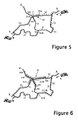
- track 30 now extends well past junction [1,3] along roads 1 and 3 to termination points 31 A, B and C, whilst track 35 extends well beyond junction [1,3] in the opposite direction to terminate at points 36A, B and C.
- the overlap route segments 41 define the range of locations that satisfy the bounds set by the distances MA(X, P A,B ) and MA(Y, P A,B ). These distances thus provide inadequate information to uniquely place P AB on the map.
- the process 26D can apply a probability rule to the effect that where there is little or no ambiguity of position along one route but a very large ambiguity along another route, then it is more likely that the true position is defined by the former rather than the latter.
- Getting more Information from a Third Vehicle - Information from a third vehicle C may provide sufficient additional data to resolve or restrict ambiguities in position.
- a different road network is assumed to that of Figures 3 - 6 , this network being represented by a map (see Figure 7 ), known to vehicle A, with two arcuate roads 4 and 5 extending between source points X and Y and a third road 6 extending from source point Z and crossing road 4 at junction [4,6].
- Roads 4 and 5 present equal minimum distance routes between points X an d Y.
- vehicles X and Y have picked up location data items from source points X and Y respectively, have maintained these items as they progressed towards the points Y and X respectively, and have subsequently exchanged their location data items at their crossing point P AB .
- the location data items in A's possession immediately after meeting B thus place upper distance bounds of MA(X,P A,B ) and MA(Y,P A,B ) on the position of vehicle A.
- Vehicle C which, having passed close by source point Z where it picked up a location data item LD(Z;C), travels along road 6 and at some point P CB crosses with vehicle B (the location of the crossing point P CB is not relevant to the present discussion).
- Vehicle B receives C's location data item which now becomes location data item LD(Z;C,B).
- vehicle A receives from vehicle B not only location data item LD(Y;B) but also location data item LD(Z;C,B).
- the distance field 27B of this latter location data item contains distance quantity: MA Z ⁇ P CB + MA P CB ⁇ P AB
- the first term is the amount by which update process 26C of vehicle C updated the distance field up until its transfer of the location data item to B; the second term is the amount by which update process 26C of vehicle B has increased the distance field between receiving the location data item from C and passing it on to A.
- the distance quantity in field 27C can be expressed as a single figure or as separate amounts for each transporting entity).
- Vehicle A therefore now has a third distance bound, this time from point Z, that it can use to determine its location.
- This distance bound is used to terminate map track 60 from Z to end points 65A, B and C on roads 4 and 6.
- the branch of map track 60 that lies on the road 4 towards point X overlaps with the overlap segment 43 determined by the distance bounds from X and Y, and further limits the possible locations of vehicle A at its meeting with vehicle B to overlap segment 44.
- This diffusion of location data items from C to B to A has thus helped in the determination of the location of vehicle A.
- This diffusion of location data items can be viewed as the diffusion of inequality equations relating minimum road distance MRD to the distance quantities provided by the distance units of the vehicles involved.
- Discarding Location Data Consider the road network depicted by the map, known to vehicle B, shown in Figure 8 - this network is simply a single road 7 connecting points X and Y. In reality there may be other routes not shown on the map such as a route following track 80 (track 80 is not part of the map and is unknown to the data-handling subsystem of vehicle B).
- Vehicle A passes close by to point X where it receives a location data item, and then follows un-mapped track 80 before joining road 7 where it meets vehicle B that has previously passed point Y.
- Vehicles A and B exchange location data items.
- vehicle B now tries to establish its location.
- the location data item LD(Y;B) puts B somewhere on map track 75 from Y up to point 76 set by the distance MA(Y,P AB ) whilst location data item LD(X;A,B) puts B somewhere on map track 70 from X to point 71; there is thus a very large overlap segment 45 occasioned by the fact that A actually followed un-mapped track 80.
- Vehicle D also passes point X and travels towards point Y, this time with no deviations from road 7.
- Vehicle D crosses with vehicle B a short time before B crosses with vehicle A.
- Vehicle B receives the location data item LD(X;D) from vehicle D and this item includes the distance quantity MA(X,P BD ) in field 26B.
- MA(X,P BD ) the distance quantity in field 26B.
- MA X ⁇ P BD + MA P BD ⁇ P BA which represents a total mileage accumulation from point X.
- this total mileage from X contained in LD(X;D,B) will be less than the total mileage from X given by the value MA(X,P AB ) contained in the LD(X;A) transferred to B by A.
- the upper bound on the distance from X contained LD(X;D,B) is a tighter bound than that contained in LD(X;A) and the latter location data item can be discarded.
- the bound on distance from X set by LD(X;D,B) is the track 77 (shown chain-dashed) of D along road 7 to point 78 where it crossed with B plus the further track (shown as a small dotted line) along road 7 to point 79.
- the uncertainty on the position of vehicle B at its point of crossing of vehicle A is thus represented by the overlap segment 46 between point 79 and the point 76 corresponding to the maximum distance of B from Y.
- Determining Direction of Travel By determining successive locations of a vehicle as new location data items are received, it is generally possible to determine the direction of travel of the vehicle.
- the location and direction of travel information permits the data handling subsystem to predict where the vehicle will be in a few minutes and to alert the user as to upcoming features and facilities. For example, in Figure 9 the vehicle B after the second location event can anticipate that shop 95 will be reached shortly and can therefore alert the vehicle driver accordingly.
- the location-dependent information about features and facilities required for this service are, for example, stored with the map data or passed to the vehicle in the short-range messages used to pass the location data items.
- This second difference means that the distance quantity contained in field 26B of a location data items will generally simply determine the radius of a circle, centered on the corresponding known location, that corresponds to the maximum distance of travel of the location data item from the known point. The location of the user is then restricted to the overlap of the maximum-travel circles centered on the known location points for which the entity concerned holds location data items.
- map-based constraints can be applied in much the same way as for the vehicle embodiments in cases where it is known that pedestrians are constrained to certain routes or areas. The most likely constraints are forbidden areas (e.g. restricted-access buildings) and rights-of-way across private land.
- Figure 10 illustrates an example involving three location-data item source points X, Y and Z, and three pedestrians F, G and H equipped with mobile devices having the Figure 2 functionality.
- Source points X and Z are situated on the boundary of a forbidden area 100 known at least to the device carried by pedestrian G whose progress will be considered below.
- Source Y is, for example, mounted on a street light.
- Location data item LD(Z;F) is passed from F to G and is used by G along with its location data item LD(X;G) to determine its position, taking account of the constraints presented by its map data (that is, the area 100).
- the maximum distance of the crossing point P GF from Z is set by the value MA(Z,P GF ) contained in LD(X;G) passed from G to F (for convenience, the "MA" ("Milometer Advance") label is retained here, notwithstanding that the distance traveled is estimated on the basis of elapsed time and speed value).
- the bound of the locations that could have been reached from Z is delimited by semi-circular arc 102 centered on Z with radius MA(Z,P GF ), and quarter-circle arc 103 centered on corner 104 of area 100 with radius equal to the difference between MA(Z,P GF :) and the distance from Z to corner 104.
- the maximum distance of the crossing point P GF from X is set by the value MA(X,P GF ), the bound of the locations that could have been reached being delimited by semicircular arc 105 centered on X with radius MA(X,P GF ), and quarter-circle arc 106 centered on corner 107 with a radius equal to the difference between MA(X,P GF ) and the distance from X to corner 107.
- the two bounded areas overlap in overlap zone 140 which therefore defines the possible location of crossing point P GF .
- Pedestrian G continues and in due course meets pedestrian H who has previously passed close to source point Y.
- Location data item LD(Y;H) is passed from H to G.
- G now recalculates his position based on the circle 110 defining the maximum distance of the meeting point P GH from Y - that is, MA(Y,P GH ) - and arcs 111 and 112 that delimit the further progress of G from his meeting with F.
- arc111 corresponds to arc 106 bounding the distance of G from X but has a larger radius to reflect the further distance MA(P GF ,P GH ) traveled by G since meeting F; similarly, arc 112 corresponds to arc 102 bounding the distance of G from Y but with a larger radius to reflect the further distance MA(P GF ,P GH ) traveled by G. Circle 110 and arcs 111, 112 delimit an overlap area 141 within which meeting point P GH must lie.
- This upper bound speed can be preset into all the mobile devices for the purposes of effecting distance calculations (distance unit 25 in Figure 2 ). Provided pedestrians walk at or near this upper bound speed, and further provided that they walk in reasonably straight lines, accurate location estimates can be derived. Whilst there will inevitably be some people who will be walking well below the upper bound speed, a location data item received from such a pedestrian is likely to be rapidly discarded in favor of tighter bound data received from another pedestrian.
- the data-handling subsystem 22 is operative to detect when this happens on the basis of detecting when this upper bound speed is unable to account for the pedestrian concerned moving between two source points within an indicated time interval. For example, if person G passes point X and then time T later G passes point Y, and G has been running between the two, then by dividing the distance as calculated from the electronic map between X and Y, by the time T, it can be detected that G is proceeding at a speed above the upper bound.
- G's mobile device detects that it is traveling above the upper bound speed, it is arranged to stop diffusing location data items for a period of time. This is done to prevent errors in the location calculations of other devices consequential on G exceeding the upper bound.
- G can still diffuse location relevant information. In the event of location data items being embedded in a location relevant information message, ceasing to diffuse location information may be simply achieved by setting a bit in the message to indicate in effect 'the location information is suspect'. However, G exceeding the upper bound does not imply that G cannot fix its location. G can still receive diffused location information from other devices and so calculate location. G simply should not participate in further diffusing location information.
- data-handling subsystem 22 can determine that a device is being carried at a speed above the assumed upper bound. For example, if G passes point X, and F passes point Z, and G and F meet after respective times T G and T F after passing the respective points X, Z, and the distance between X and Z divided by (T G + T F ) gives a speed greater than the upper bound speed, then clearly at least one of G and F has been proceeding at a speed greater than the upper bound speed. In these circumstances, both G and F should cease to diffuse location information.
- the upper bound speed could be determined by subsystem 22 for each device from observations similar to those discussed above for detecting excess speeds. If a pedestrian, for whatever reason, never traveled above a certain speed, then this individual upper bound, rather than a general upper bound, could be used to further improve the accuracy of the location estimates.
- the actual range of the short-range wireless transceivers of the mobile entities has not been taken into account. This is generally acceptable for the vehicle case since the transceiver range will be small compared with the distances traveled by the vehicle. However, in the case of pedestrians, the transceiver range is a greater fraction of the typical distance being moved by a pedestrian; furthermore in a crowded area, such as a shopping mall, a message can diffuse quickly from device to device making the cumulative range of the utilized devices by far the greatest likely contributor to message displacement from the location data source.
- This factor can be taken into account by increasing, in transmitted messages, the value of the distance quantity 27B (measured and/or estimated maximum distance from the location-data item source) by a transceiver range value. Since, of course, the range of the transceiver is a function not only of the transmitter but also of the sensitivity of the receiving device, this range value added to the distance quantity 27B should be for standard receiving conditions. If this range value is added at each hop from device to device, the distance quantity 27B will be increased by the sum of the ranges of the participating devices.
- the receiving device can choose whether to add the full range value to the received distance quantity 27B or whether only a percentage amount should be added because the receiving device believes itself not to be at the maximum range from the transmitting device.
- a belief can be derived from the received signal strength, a strong signal indicating that the transmitting device is closer than if a weak signal is received.
- the transmitting device can automatically add 100% of its range to the distance quantity 27B when transmitting, the receiving device then being responsible for subtracting an appropriate percentage of the transmitting devices range (this range value still being included in the transmitted message).
- Increasing the distance quantity 27B of a location data item according to displacement of the item can be effected for any type of entity (mobile or static, vehicle or person) and regardless of the usage to which the location data item is subsequently put by a receiving entity.
- Static entities are entities that do not normally move. Such entities can be treated as if they were pedestrian entities but with a maximum walking speed of zero. Thus a static entity would transmit received location data items with the same value of the distance quantity 27B as received (or only increased by a range value as described above).
- a typical static entity is a PC or peripheral in an office. Assuming there are fixed location beacons in the environment (but not necessarily in immediate range of a static entity), then over a period of time the static entity will accumulate a substantial amount of location data from passing mobile entities and derive a fairly accurate idea of its location which it can pass on .
- a static entity may also be movable.
- a static device When a static device is moved into a new location, it must discard its previously-determined location and either update all its location data items by an estimate of the distance it has been moved or discard those items entirely and start afresh.
- the static item is very likely only to be moved when powered down so that it cannot, with any reliability, form a time-based estimate of how far it has been moved; as a result, it is likely that all location data will need to be discarded.
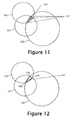
- a general approach for determining best estimate of location is as follows. In general there will be an area 134 (see Figure 11 ) formed by the overlap of the areas of multiple FAP circles 130 to 132, i.e. the area of overlap will be in all FAP circles. This is found by finding the points of intersection between each pair of FAP circles. The (in general 2) points of intersection between 2 circles can be found using a well known and simple formula which derive the coordinates of the points of intersection.
- the points which make up the vertices of the boundary of the area of overlap134 will be those points 135 of intersection which are inside all of the other circles, again easily determined computationally.
- a simple best estimate of position can be made by taking the mean (average) of the vertices 135 of the area of overlap 134.
- Another way of making the best estimate is to approximate the area of overlap 134 as having straight lines, (so the area ofoverlap is approximated as a polygon, in this particular case a triangle 137 as illustrated in Figure 12 ) and to work out the center of gravity of the polygon.
- the center of gravity is in some sense the center of the area of overlap.
- the radii of the circles can be increased (rather than decreased) by the same percentage amount until a touching point is reached, the touching point again being the location best estimate.
- the distance quantity 27B in a location data item may well only be an estimate of the maximum distance of an entity from the specified FAP and could therefore be under-valued.
- FAP circle that is, a location data item with the center of a FAP circle and radius, these being the elements 27A and B of the Figure 2 location data item 27
- a less stringent strategy is to take the set of FAP circles which contribute to the vertices of the area of overlap, and if any of the FAP circles encloses all of the circles in the above set, then to eliminate the enclosing FAP circle from being sent on in any future exchange of information with other mobile entities.
- route constraints these can be used to further limit where the mobile entity lies within the overlap zone.
- the type of route constraint is likely to influence what method is used to derive a best estimate of position within the overlap zone.
- a simply midway position along a road between the beginning and end of the overlap zone is likely to be a good solution with account being taken of the likely decisions at route junctions based on road importance, intended or likely destination, etc.
- an entity will have received one or more location data items LD1 to LD n each comprising the coordinates (typically x , y coordinates) of a specific known location, and a distance quantity d that is a measure or estimate of the maximum distance to the known location based on the distance traveled by carrying entities and/or the transmission hop distance each time the location data item is passed on.
- the entity possesses location information that can be represented as: d ⁇ 1 , x ⁇ 1 , y ⁇ 1 ; ( d ⁇ 2 , x ⁇ 2 , y ⁇ 2 ) ; ( d ⁇ 3 , x ⁇ 3 , y ⁇ 3 ) ; etc.
- the type of map-based route constraint applied when determining location depends on the general type of mobile entity being considered (in the foregoing, whether vehicles or pedestrians are being considered). It is possible, in fact, to allow for location data items to be exchanged between different types of mobile entity.
- railway locomotives could be configured as mobile entities similar to vehicles and used to provide location data items to vehicles traveling near the locomotive; in this case, when considering the distance quantity in field 27B of a location data item just received from a locomotive, the receiving vehicle should constrain the corresponding map track to be along railway lines on the vehicle's map.
- field 27C of a location data item to indicate what type of constraint is applicable to the distance quantity in field 27B, the field being inspected by process 26D before the latter utilizes the distance quantity in location determination.
- the distance quantity in field 27B is made up of terms associated different types of route constraint, then these terms should be separately stored in field 27B and corresponding route constraint indicators stored in field 27C.
- the source points for location data items need not be fixed but could be mobile devices that derive their own location by some other means (such as by using a GPS system or a cellular radio network location technique).
- the map data may be stored semi-permanently in the entities.
- the map data can be automatically downloaded - for example, when a pedestrian carrying a mobile device enters a shopping mall.
- a third possibility is that the map data is sent to mobile entities using diffusion.
- any suitable coordinate system can be employed for specifying locations; for example a latitude/longitude based coordinate system can be used or a locally defined coordinate system (the latter potentially being more appropriate for use in an environment such as a shopping mall or theme park).
- the location determination operation can be arranged to determine which location zone is the most probable on the basis of one or more of the following probability indicators:
Landscapes
- Engineering & Computer Science (AREA)
- Physics & Mathematics (AREA)
- General Physics & Mathematics (AREA)
- Radar, Positioning & Navigation (AREA)
- Remote Sensing (AREA)
- Computer Networks & Wireless Communication (AREA)
- Signal Processing (AREA)
- Navigation (AREA)
- Mobile Radio Communication Systems (AREA)
- Traffic Control Systems (AREA)
Claims (36)
- Procédé de dissémination d'informations de position, dans lequel des éléments de données de position (27) qui prennent leur origine à des positions connues (X, Y, Z) sont transférés vers, et diffusés entre, des entités (20) par une communication à courte distance, caractérisé en ce que chaque élément de données de position (27) comprend une quantité associée à une distance (27B) qui indique une valeur de limite supérieure pour la distance par rapport à une dite position connue (27A) spécifiée dans l'élément de données de position (27), lesdites entités (20) mettant à jour (26C) les quantités associées à une distance (27B) des éléments de données de position (27) dont elles assurent la gestion, avant de les transférer, de façon à prendre en compte une course perçue de ces éléments de données de position.
- Procédé selon la revendication 1, dans lequel une dite entité (20) - qui est une entité mobile - augmente (26C) la quantité associée à une distance (27B) du ou de chaque élément, de données de position (27) dont elle assure la gestion, d'une quantité qui correspond à la distance parcourue par l'entité (20) tout en conservant l'élément de données de position.
- Procédé selon la revendication 2, dans lequel l'entité mobile est un véhicule (A-E) équipé d'un appareil émetteur/récepteur à courte distance (21) et d'un compteur odométrique (25), le véhicule augmentant (26C) la quantité associée à une distance (27B) de ses éléments de données de position (27) de la distance parcourue par le véhicule, telle qu'elle est indiquée par ledit compteur odométrique.
- Procédé selon la revendication 2, dans lequel l'entité mobile est un piéton (F, G) qui porte un dispositif mobile (20) équipé d'un appareil émetteur/récepteur à courte distance (21), le dispositif (20) effectuant une estimation de la distance maximum qui est susceptible d'avoir été parcourue par le piéton sur la base d'une valeur de vitesse et d'un temps écoulé, et le dispositif (20) augmentant (26C) la quantité associée à une distance (27B) de ses éléments de données de position (27) de ladite estimation de la distance maximum qui est susceptible d'avoir été parcourue par le piéton.
- Procédé selon la revendication 4, dans lequel ladite vitesse est la vitesse maximum du piéton (F, G), telle que déterminée sur la durée par le dispositif (20) sur la base du temps mis par le piéton pour se déplacer entre des positions, comme déterminées par l'opération de détermination de position (26D).
- Procédé selon la revendication 4, dans lequel ladite vitesse est une vitesse maximum standard pour des piétons qui marchent (F, G), le dispositif (20) :◆ surveillant la vitesse actuelle du piéton en se basant sur le temps mis par le piéton pour se déplacer entre des positions d'un endroit connu ; et◆ dans le cas où la vitesse actuelle du piéton dépasse ladite vitesse maximum standard, le dispositif empêchant le transfert d'éléments de données de position de l'entité mobile (20) vers d'autres dites entités.
- Procédé selon la revendication 1, dans lequel la quantité associée à une distance (27B) dudit élément de données de position (27) augmente (26C), pour chaque bond de transmission entre deux entités (20), d'une quantité liée à la plage de transmission de l'entité émettrice.
- Procédé selon la revendication 7, dans lequel l'augmentation de ladite quantité associée à une distance (27B) est une valeur comprise dans une plage fixe pour l'entité émettrice (20), cette valeur de plage étant ajoutée par l'entité émettrice à ladite quantité associée à une distance.
- Procédé selon la revendication 7, dans lequel ladite quantité associée à une distance (27B) comprend un compteur de bonds qui fournit une mesure de la distance parcourue par l'élément de données de position (27) concerné, en résultat de bonds de transmission.
- Procédé selon la revendication 7, dans lequel l'augmentation de ladite quantité associée à une distance (27B) est une fraction d'une valeur de plage pour l'entité émettrice, cette fraction étant déterminée par l'entité émettrice (20) en fonction de la force du signal reçu, l'entité émettrice ajustant ladite quantité associée à une distance en conséquence.
- Procédé selon la revendication 1, dans lequel une dite entité (20) - qui est une entité mobile - augmente (26C) la quantité associée à une distance (27B) du ou de chaque élément, de données de position (27) dont elle assure la gestion, à la fois d'une quantité qui correspond à la distance parcourue par l'entité tout en conservant l'élément de données de position (27), et d'une quantité liée à la plage de transmission de l'entité émettrice par rapport à l'une d'une réception et d'une transmission de l'élément de données de position par l'entité mobile.
- Procédé selon l'une quelconque des revendications 1, 2, 7 ou 11, dans lequel une dite entité (20) détermine sa position en déterminant une position qui est simultanément cohérente, ou quasiment cohérente, avec les valeurs de limite supérieure (27B) dont elle a connaissance en résultat d'éléments de données de position (27) qu'elle a reçus.
- Procédé selon la revendication 12, dans lequel, dans la détermination de sa position, ladite entité (20) applique une ou plusieurs contraintes de route concernant la manière dont les éléments de données de position (27) sont transférés vers l'entité mobile.
- Procédé selon la revendication 13, dans lequel, dans la détermination de sa position, ladite entité (20) applique une contrainte selon laquelle lesdites valeurs de limite supérieure (27B) sont des distances le long de routes prédéterminées à partir des positions connues concernées.
- Procédé selon la revendication 14, dans lequel lesdites routes prédéterminées sont des routes sur une carte, représentées par des données cartographiques connues de l'entité (20).
- Procédé selon la revendication 13, dans lequel, dans la détermination de sa position, ladite entité (20) applique une contrainte selon laquelle lesdites valeurs de limite supérieure (27B) sont des distances le long de routes indéterminées qui évitent des zones particulières.
- Procédé selon la revendication 13, dans lequel un élément de données de position (27) reçu comprend une indication d'un type de contrainte qui doit être appliquée sur au moins une certaine longueur de la valeur de distance limite supérieure associée (27B).
- Procédé selon la revendication 12, dans lequel, au moment où ladite entité (20) reçoit un élément de données de position (27) indiquant une valeur de distance limite supérieure (27B) par rapport à une position connue (X, Y, Z) pour laquelle un élément de données de position (27) a été précédemment reçu, un des éléments de données de position est mis au rebut, l'élément mis au rebut étant celui qui indique la valeur de distance limite supérieure la plus élevée par rapport à la position connue en tenant compte d'une ou des augmentations due(s) à un déplacement de l'entité après la réception de l'élément.
- Procédé selon la revendication 12, dans lequel, lors de la détermination de sa position par ladite entité (20) - une opération qui indique initialement une pluralité de zones de position (43, 44) dans lesquelles l'entité pourrait se trouver, l'entité cherche à déterminer la zone de position la plus probable en se basant sur un ou plusieurs des indicateurs de probabilité suivants :◆ la dimension des zones de position par rapport à un degré attendu d'incertitude liée à la position ;◆ la nature des routes suivies afin d'arriver aux zones de position à partir des positions connues concernées ;◆ un historique préalable de positions visitées ou traversées par l'entité ;◆ la correspondance entre des événements de circulation détectés - comme des virages, par exemple - et des opportunités que ces événements se produisent le long de routes menant aux zones de position.
- Procédé selon la revendication 12, dans lequel la position de ladite entité (20) est déterminée à deux occasions distinctes, la dernière détermination réalisée utilisant des données de position reçues consécutivement à la première détermination, ce qui permet de faire dériver une indication de la direction moyenne de circulation.
- Procédé selon la revendication 12, dans lequel une estimation de la position la plus approchante est dérivée à l'intérieur d'une zone (134) de positions possibles sur la base d'une moyenne réalisée par rapport à des sommets (135) de cette zone.
- Procédé selon la revendication 21, dans lequel ladite estimation est obtenue en réalisant une moyenne des valeurs de coordonnées desdits sommets (135).
- Procédé selon la revendication 21, dans lequel ladite estimation est réalisée en trouvant le centre de gravité d'un polygone délimité par lesdits sommets (135).
- Entité (20) pourvue d'un système de découverte de position comprenant un appareil émetteur/récepteur à courte distance (21) pour échanger des éléments de données de position (27) avec des entités émettrices se trouvant actuellement à proximité, et une mémoire (23) pour stocker les éléments de données de position (27) reçus, caractérisée en ce que le système de découverte de position comprend par ailleurs :◆ des moyens de mise à jour (22, 26C) pour maintenir à jour des éléments de données de position (27) reçus en mettant à jour une quantité associée à une distance (27B) de chaque élément de données de position, de façon à prendre en compte une course perçue de l'élément de données de position, ladite quantité associée à une distance (27B) étant représentative d'une distance limite supérieure par rapport à une position connue (27A) spécifiée dans l'élément de données de position (27) ; et◆ des moyens de détermination de position (22, 26D) pour effectuer une détermination de position en déterminant des positions qui sont simultanément cohérentes, ou pratiquement cohérentes, avec les distances limites supérieures connues de l'entité ; l'entité (20) étant configurée de façon à, lors d'une rencontre avec une autre entité, utiliser son appareil émetteur/récepteur à courte distance (21) pour transférer à cette autre entité des éléments de données de position (27) précédemment reçus, dont les quantités associées à une distance (27B) ont été mises à jour par les moyens de mise à jour.
- Entité selon la revendication 24, dans laquelle l'entité est une entité mobile, et les moyens de mise à jour (22, 26C) sont configurés de façon à maintenir à jour les éléments de données de position (27) en augmentant la quantité associée à une distance (27B) du ou de chaque élément de données de position d'une quantité qui correspond à la distance parcourue par l'entité tout en conservant l'élément de données de position.
- Entité selon la revendication 25, dans laquelle l'entité est un véhicule (A-E) équipé d'un compteur kilométrique (25), les moyens de mise à jour (22, 26C) étant configurés de façon à augmenter la quantité associée à une distance des éléments de données de position de la distance parcourue par le véhicule, telle qu'elle est indiquée par ledit compteur kilométrique.
- Entité selon la revendication 25, dans laquelle l'entité (20) est un dispositif mobilier prévu pour être porté par un piéton (F, G), les moyens de mise à jour (22, 26C) étant configurés de façon à estimer la distance maximum qui est susceptible d'avoir été parcourue par le piéton sur la base d'une valeur de vitesse et d'un temps écoulé, et de façon à augmenter la quantité associée à une distance (27B) des éléments de données de position (27) de ladite estimation de la distance maximum qui est susceptible d'avoir été parcourue par le piéton.
- Entité selon la revendication 27, dans laquelle les moyens de détermination de position (22, 26D) sont configurés par ailleurs de façon à déterminer une vitesse maximum du piéton (F, G) en se basant sur le temps mis par le piéton pour se déplacer entre des positions déterminées par les moyens de détermination de position, les moyens de mise à jour (22, 26C) étant configurés de façon à utiliser cette vitesse maximum en tant que ladite valeur de vitesse pour estimer la distance maximum qui est susceptible d'avoir été parcourue par le piéton.
- Entité selon la revendication 27, dans laquelle ladite valeur de vitesse est une vitesse maximum standard pour des piétons qui marchent (F, G), le dispositif (20) étant configuré de façon à :◆ surveiller la vitesse actuelle du piéton en se basant sur le temps mis par le piéton pour se déplacer entre des positions (X, Y, Z) d'un endroit connu, comme cela est déterminé par les moyens de détermination de position (22, 26D) ; et◆ dans le cas où la vitesse actuelle du piéton dépasse ladite vitesse maximum standard, empêcher le transfert d'éléments de données de position (27) de l'entité mobile (20) vers d'autres dites entités par les moyens de communication à courte distance (21).
- Entité selon la revendication 24, dans laquelle les moyens de mise à jour (22, 26C) sont configurés de façon à maintenir à jour les éléments de données de position (27) en augmentant la quantité associée à une distance (27B) de chacun desdits éléments de données de position (27) d'une quantité associée à la plage de transmission de l'entité émettrice par rapport à l'une d'une réception et d'une transmission de l'élément de données de position par l'entité mobile (20).
- Entité selon la revendication 30, dans laquelle lesdits moyens de mise à jour (22, 26C) sont configurés de façon à augmenter la quantité associée à une distance (27B) d'un élément de données de position (27) immédiatement avant que l'entité (20) transmette cet élément vers une autre entité, cette augmentation étant une valeur comprise dans une plage de transmission fixe.
- Entité selon la revendication 30, dans laquelle lesdits moyens de mise à jour (22, 26C) sont configurés de façon à augmenter la quantité associée à une distance (27B) d'un élément de données de position (27) reçu d'une autre entité d'une fraction d'une valeur de plage pour l'entité émettrice, cette fraction étant déterminée par les moyens de mise à jour en fonction de la force du signal reçu, telle que mesurée par les moyens de communication à courte distance (21).
- Entité selon l'une quelconque des revendications 24, 25 ou 30, dans laquelle, dans la détermination de la position de l'entité (20), les moyens de détermination de position (22, 26D) sont configurés de façon à appliquer une ou plusieurs contraintes de route concernant la manière dont les éléments de données de position sont transférés vers l'entité mobile.
- Entité selon la revendication 33, dans laquelle, dans la détermination de la position de l'entité (20), les moyens de détermination de position (22, 26D) sont configurés de façon à appliquer une contrainte selon laquelle lesdites distances de limite supérieure (27B) sont des distances le long de routes prédéterminées à partir des positions connues concernées.
- Entité selon la revendication 33, dans laquelle, dans la détermination de la position de l'entité (20), les moyens de détermination de position (22, 26D) sont configurés de façon à appliquer une contrainte selon laquelle lesdites distances de limite supérieure (27B) sont des distances le long de routes indéterminées qui évitent des zones particulières.
- Entité selon l'une quelconque des revendications 24, 25 ou 30, dans laquelle les moyens de détermination de position (22, 26D) sont configurés de façon à faire dériver une estimation de la position la plus approchante à l'intérieur d'une zone (134) de positions possibles sur la base d'une moyenne réalisée par rapport à des sommets (135) de cette zone.
Applications Claiming Priority (8)
| Application Number | Priority Date | Filing Date | Title |
|---|---|---|---|
| GB0017456A GB0017456D0 (en) | 2000-07-18 | 2000-07-18 | Location discovery |
| GB0017456 | 2000-07-18 | ||
| GB0027384A GB0027384D0 (en) | 2000-11-09 | 2000-11-09 | Location discovery |
| GB0027384 | 2000-11-09 | ||
| GB0102417A GB0102417D0 (en) | 2001-01-31 | 2001-01-31 | Location Discovery |
| GB0102417 | 2001-01-31 | ||
| GB0114144A GB0114144D0 (en) | 2001-06-11 | 2001-06-11 | Location discovery |
| GB0114144 | 2001-06-11 |
Publications (3)
| Publication Number | Publication Date |
|---|---|
| EP1174728A2 EP1174728A2 (fr) | 2002-01-23 |
| EP1174728A3 EP1174728A3 (fr) | 2002-11-06 |
| EP1174728B1 true EP1174728B1 (fr) | 2008-09-24 |
Family
ID=27447862
Family Applications (1)
| Application Number | Title | Priority Date | Filing Date |
|---|---|---|---|
| EP01305936A Expired - Lifetime EP1174728B1 (fr) | 2000-07-18 | 2001-07-10 | Diffusion de données de position et decouverte de la position |
Country Status (4)
| Country | Link |
|---|---|
| US (1) | US7026983B2 (fr) |
| EP (1) | EP1174728B1 (fr) |
| JP (1) | JP2002124913A (fr) |
| DE (1) | DE60135891D1 (fr) |
Families Citing this family (55)
| Publication number | Priority date | Publication date | Assignee | Title |
|---|---|---|---|---|
| EP1267175A3 (fr) | 2001-06-11 | 2003-10-15 | Hewlett-Packard Company | Détermination d'une position en utilisant des données élémentaires de positionnement reçues par transmission à courte portée |
| EP1267541A1 (fr) | 2001-06-11 | 2002-12-18 | Hewlett-Packard Company | Procédé et système de la détermination de position utilisant des éléments de données reçus par communication sur courtes distances |
| US20030069692A1 (en) * | 2001-10-10 | 2003-04-10 | Krasner Norman F. | Methods and apparatuses for controlling distribution of location information |
| US6804525B2 (en) * | 2002-04-02 | 2004-10-12 | Motorola, Inc. | Method and apparatus for facilitating two-way communications between vehicles |
| US7123925B2 (en) * | 2002-06-18 | 2006-10-17 | British Telecommunications Public Limited Company | Method and apparatus for locating devices |
| CA2394770A1 (fr) | 2002-07-23 | 2004-01-23 | Boomerang Tracking Inc. | Systeme de location de vehicules utilisant un reseau cinetique |
| US6988032B2 (en) * | 2003-04-29 | 2006-01-17 | Lucent Technologies Inc. | Generating vehicle traffic data from raw location data for mobile units |
| US8140013B1 (en) | 2003-06-04 | 2012-03-20 | Cypress Semiconductor Corporation | Wireless communication device and method |
| US7848703B1 (en) * | 2004-12-30 | 2010-12-07 | Cypress Semiconductor Corporation | Method and apparatus for binding wireless devices |
| RU2227373C1 (ru) * | 2003-08-12 | 2004-04-20 | Громаков Юрий Алексеевич | Способ сотовой связи |
| JP4502361B2 (ja) * | 2003-09-30 | 2010-07-14 | キヤノン株式会社 | 指標姿勢検出方法および装置 |
| US20050075836A1 (en) * | 2003-10-03 | 2005-04-07 | Jason Arthur Taylor | Forensic person tracking method and apparatus |
| US7493086B2 (en) * | 2004-10-19 | 2009-02-17 | Benjamine Joel Landry | Methods of attribute collection for mapping |
| US8606516B2 (en) | 2004-11-30 | 2013-12-10 | Dash Navigation, Inc. | User interface system and method for a vehicle navigation device |
| US7263375B2 (en) * | 2004-12-21 | 2007-08-28 | Lockheed Martin Corporation | Personal navigation assistant system and apparatus |
| JP4572698B2 (ja) * | 2005-02-21 | 2010-11-04 | 日本電気株式会社 | 携帯端末装置、無線通信システム、位置情報算出方法及びプログラム |
| JP2006270286A (ja) * | 2005-03-23 | 2006-10-05 | Nec Corp | 移動体通信システム、移動体通信端末、基地局装置、上位装置、及び、移動体通信端末の位置登録方法 |
| US20070082689A1 (en) * | 2005-10-06 | 2007-04-12 | Talty Timothy J | Alert notification network |
| US8275402B2 (en) * | 2005-10-06 | 2012-09-25 | GM Global Technology Operations LLC | Alert notification network |
| US9478133B2 (en) * | 2006-03-31 | 2016-10-25 | Volkswagen Ag | Motor vehicle and navigation arrangement for a motor vehicle |
| US20070233371A1 (en) | 2006-03-31 | 2007-10-04 | Arne Stoschek | Navigation system for a motor vehicle |
| US8886125B2 (en) | 2006-04-14 | 2014-11-11 | Qualcomm Incorporated | Distance-based association |
| US9215581B2 (en) * | 2006-04-14 | 2015-12-15 | Qualcomm Incorported | Distance-based presence management |
| US20070249288A1 (en) * | 2006-04-14 | 2007-10-25 | Kamran Moallemi | Distance-based security |
| US8538676B2 (en) * | 2006-06-30 | 2013-09-17 | IPointer, Inc. | Mobile geographic information system and method |
| US8374623B2 (en) * | 2006-07-21 | 2013-02-12 | Microsoft Corporation | Location based, software control of mobile devices |
| US7683835B2 (en) * | 2006-08-15 | 2010-03-23 | Computer Associates Think, Inc. | System and method for locating wireless devices |
| US7751971B2 (en) * | 2007-01-17 | 2010-07-06 | Microsoft Corporation | Location mapping for key-point based services |
| US8837724B2 (en) * | 2007-03-27 | 2014-09-16 | Qualcomm Incorporated | Synchronization test for device authentication |
| US20080262928A1 (en) * | 2007-04-18 | 2008-10-23 | Oliver Michaelis | Method and apparatus for distribution and personalization of e-coupons |
| CN101682900B (zh) * | 2007-06-01 | 2013-05-29 | 松下电器产业株式会社 | 通信系统、无线通信终端、位置推定装置、通信中继装置和连接站 |
| US20090076911A1 (en) * | 2007-06-20 | 2009-03-19 | Dang Minh Vo | Mobile coupons utilizing peer to peer ranging |
| US9483769B2 (en) * | 2007-06-20 | 2016-11-01 | Qualcomm Incorporated | Dynamic electronic coupon for a mobile environment |
| US9141961B2 (en) * | 2007-06-20 | 2015-09-22 | Qualcomm Incorporated | Management of dynamic mobile coupons |
| US9524502B2 (en) | 2007-06-20 | 2016-12-20 | Qualcomm Incorporated | Management of dynamic electronic coupons |
| ES2306616B1 (es) | 2008-02-12 | 2009-07-24 | Fundacion Cidaut | Procedimiento de determinacion de la luminancia de señales de trafico y dispositivo para su realizacion. |
| US10237679B2 (en) * | 2008-06-27 | 2019-03-19 | Here Global B.V. | Method, apparatus, and computer program product for location sharing |
| US8401560B2 (en) * | 2009-03-31 | 2013-03-19 | Empire Technology Development Llc | Infrastructure for location discovery |
| US8054762B2 (en) * | 2009-03-31 | 2011-11-08 | Technology Currents Llc | Network node location discovery |
| US8369242B2 (en) | 2009-03-31 | 2013-02-05 | Empire Technology Development Llc | Efficient location discovery |
| US20100280960A1 (en) * | 2009-05-04 | 2010-11-04 | Agisilaos-Georgios Ziotopoulos | Apparatus and methods for negotiating discount offers |
| WO2011066473A1 (fr) * | 2009-11-25 | 2011-06-03 | Maxlinear, Inc. | Géolocalisation coopérative |
| US8644854B2 (en) * | 2009-12-03 | 2014-02-04 | Osocad Remote Limited Liability Company | System and method for processing enhanced data exchanged with an enhanced mobile station via a wireless connection |
| US8531333B2 (en) | 2009-12-10 | 2013-09-10 | Maxlinear, Inc. | Intermittent tracking for GNSS |
| KR101424747B1 (ko) * | 2010-11-15 | 2014-08-01 | 한국전자통신연구원 | Wi-Fi 시스템에서 접속 지점 위치 추정 방법 및 장치 |
| US20130190006A1 (en) * | 2011-02-15 | 2013-07-25 | Telefonaktiebolaget L M Ericsson (Publ) | Methods and Systems for Enabling User Activity-Aware Positioning |
| US10542372B2 (en) | 2011-03-15 | 2020-01-21 | Qualcomm Incorporated | User identification within a physical merchant location through the use of a wireless network |
| US20140333482A1 (en) * | 2013-05-10 | 2014-11-13 | Telcom Ventures, Llc | Methods of position-location determination using a high-confidence range, and related systems and devices |
| KR102280542B1 (ko) * | 2015-01-13 | 2021-07-22 | 삼성전자 주식회사 | 전자 장치, 무선 중계 장치, 및 무선 중계 장치의 위치 정보 제공 방법 |
| US9918191B2 (en) | 2015-10-26 | 2018-03-13 | Intel Corporation | Mobile geo-fence system |
| US9848301B2 (en) | 2015-11-20 | 2017-12-19 | At&T Intellectual Property I, L.P. | Facilitation of mobile device geolocation |
| US9998876B2 (en) | 2016-07-27 | 2018-06-12 | At&T Intellectual Property I, L.P. | Inferring user equipment location data based on sector transition |
| US10656240B2 (en) * | 2016-08-31 | 2020-05-19 | Harris Global Communications, Inc. | Hybrid TDOA closed form hyperbolic and spherical iteration geo-location technique |
| EP3530065B1 (fr) | 2016-10-24 | 2020-12-02 | Qualcomm Incorporated | Procédures de zone de radiomessagerie et signalisation de connexion |
| US20200011696A1 (en) * | 2018-07-03 | 2020-01-09 | Honeywell International Inc. | Indoor wayfinding to equipment and infrastructure |
Family Cites Families (30)
| Publication number | Priority date | Publication date | Assignee | Title |
|---|---|---|---|---|
| US5375161A (en) | 1984-09-14 | 1994-12-20 | Accessline Technologies, Inc. | Telephone control system with branch routing |
| JPH0656975B2 (ja) * | 1986-02-12 | 1994-07-27 | 株式会社日立製作所 | 移動体通信を用いた車両位置検出方式 |
| US5428544A (en) * | 1990-11-05 | 1995-06-27 | Norm Pacific Automation Corporation | Traffic information inter-vehicle transference and navigation system |
| US5652570A (en) * | 1994-05-19 | 1997-07-29 | Lepkofker; Robert | Individual location system |
| JPH0886853A (ja) * | 1994-09-14 | 1996-04-02 | East Japan Railway Co | 移動体間相対位置検知システム |
| GB2298766B (en) | 1995-03-10 | 1999-07-07 | Nec Corp | Mobile communication system |
| US5875400A (en) | 1995-04-18 | 1999-02-23 | Northern Telecom Limited | Cellular mobile communications system |
| JPH1032538A (ja) * | 1996-07-17 | 1998-02-03 | Nippon Telegr & Teleph Corp <Ntt> | 移動体通信方法および装置 |
| US6236335B1 (en) | 1996-09-17 | 2001-05-22 | Ncr Corporation | System and method of tracking short range transmitters |
| US6047183A (en) | 1997-10-30 | 2000-04-04 | Ericsson Inc. | Selection of positioning handover candidates based on angle |
| EP0913965A1 (fr) | 1997-11-03 | 1999-05-06 | Canon Kabushiki Kaisha | Réduction du trafic de messages dans un réseau distribué |
| US6078818A (en) * | 1998-03-09 | 2000-06-20 | Ericsson Inc. | System and method for implementing positioning quality of service |
| EP1064760B1 (fr) | 1998-03-11 | 2002-01-02 | Swisscom Mobile AG | Procede de routage pour systemes de communication sans fil et repartis et dispositifs connus a cet effet |
| JP3037927B2 (ja) * | 1998-03-30 | 2000-05-08 | インターナショナル・ビジネス・マシーンズ・コーポレイション | 転送方法及び移動無線送受信機 |
| US6078826A (en) | 1998-05-29 | 2000-06-20 | Ericsson Inc. | Mobile telephone power savings method and apparatus responsive to mobile telephone location |
| WO1999065152A1 (fr) * | 1998-06-05 | 1999-12-16 | Epfl Service Des Relations Industrielles (Sri) | Dispositif pour systeme de communication et systeme de communication correspondant |
| GB2338374A (en) | 1998-06-10 | 1999-12-15 | Motorola Ltd | Locating a mobile telephone using time of arrival measurements |
| GB2339356B (en) | 1998-07-04 | 2003-12-10 | Peter Nicholas Taft | Location detector |
| FR2782226B1 (fr) * | 1998-08-04 | 2000-09-08 | Sagem | Procede de localisation d'un telephone mobile |
| GB2342018B (en) | 1998-09-24 | 2003-11-05 | Nokia Mobile Phones Ltd | Communication network |
| JP2000102060A (ja) * | 1998-09-25 | 2000-04-07 | Nippon Telegr & Teleph Corp <Ntt> | 移動端末における位置情報の交換方法および装置 |
| DE19849294C2 (de) | 1998-10-16 | 2001-09-27 | Daimler Chrysler Ag | Verfahren zum Verbreiten einer Nachricht |
| DE19903909A1 (de) * | 1999-02-01 | 2000-08-03 | Delphi 2 Creative Tech Gmbh | Verfahren und Vorrichtung zur Gewinnung von relevanter Verkehrsinformation und zur dynamischen Routenoptimierung |
| US6549625B1 (en) | 1999-06-24 | 2003-04-15 | Nokia Corporation | Method and system for connecting a mobile terminal to a database |
| US6275707B1 (en) * | 1999-10-08 | 2001-08-14 | Motorola, Inc. | Method and apparatus for assigning location estimates from a first transceiver to a second transceiver |
| AU3084801A (en) | 2000-01-06 | 2001-07-16 | Brightcom Technologies Ltd. | Integration of bluetooth functionality with a global positioning system |
| US6757518B2 (en) | 2000-03-11 | 2004-06-29 | Hewlett-Packard Development Company, L.P. | Position discovery using short range mobile devices |
| GB0007617D0 (en) | 2000-03-29 | 2000-05-17 | Psion Dacom Plc | A short range radio transceiver device |
| GB2364203B (en) | 2000-06-27 | 2004-03-17 | Nokia Mobile Phones Ltd | Synchronisation |
| US6327533B1 (en) * | 2000-06-30 | 2001-12-04 | Geospatial Technologies, Inc. | Method and apparatus for continuously locating an object |
-
2001
- 2001-07-10 EP EP01305936A patent/EP1174728B1/fr not_active Expired - Lifetime
- 2001-07-10 DE DE60135891T patent/DE60135891D1/de not_active Expired - Lifetime
- 2001-07-12 JP JP2001211637A patent/JP2002124913A/ja active Pending
- 2001-07-13 US US09/905,774 patent/US7026983B2/en not_active Expired - Lifetime
Also Published As
| Publication number | Publication date |
|---|---|
| US20020045455A1 (en) | 2002-04-18 |
| US7026983B2 (en) | 2006-04-11 |
| DE60135891D1 (de) | 2008-11-06 |
| JP2002124913A (ja) | 2002-04-26 |
| EP1174728A2 (fr) | 2002-01-23 |
| EP1174728A3 (fr) | 2002-11-06 |
Similar Documents
| Publication | Publication Date | Title |
|---|---|---|
| EP1174728B1 (fr) | Diffusion de données de position et decouverte de la position | |
| US8676466B2 (en) | Fail-safe speed profiles for cooperative autonomous vehicles | |
| US8958979B1 (en) | System and method for road map creation | |
| CN101936744B (zh) | 路径引导服务器装置、导航装置、路径引导系统及方法 | |
| CN101031161B (zh) | 车辆间特定路由协议和通信系统 | |
| CN102893694B (zh) | 通信装置、车辆间通信控制方法以及车辆间通信系统 | |
| US9313614B2 (en) | Method of and system for estimating position | |
| US6940451B2 (en) | Provision of navigation information | |
| US20120310520A1 (en) | Route calculation apparatus | |
| CN112602128A (zh) | 道路交通导航系统 | |
| KR20160128335A (ko) | 친숙한 루트들을 따라서 네비게이션할 때의 감소된 전력 소비 및 향상된 사용자 경험 | |
| CN108701411B (zh) | 用于车辆的行驶辅助系统的设备和方法以及用于可控的交通示意标志的控制实体的设备和方法 | |
| JP2023507088A (ja) | 交差点軌道決定およびメッセージング | |
| CN103201594A (zh) | 导航终端、导航方法以及导航程序 | |
| JP2008032563A (ja) | 集合場所決定方法および移動体情報端末及びサーバー装置 | |
| JP2004248084A (ja) | 車車間通信装置 | |
| JP2008304313A (ja) | ナビゲーション装置、配信装置、ナビゲーションシステム | |
| JP2002131067A (ja) | ナビゲーション装置、基地局装置及びこれらを用いた道路交通情報システム | |
| US12188774B2 (en) | Method and apparatus for providing multi-modal service using a personal mobility vehicle | |
| US12024056B2 (en) | Method and apparatus for managing shared personal mobility vehicle | |
| JP3705249B2 (ja) | 旅行時間算出装置及びナビゲーションシステム | |
| JP5929134B2 (ja) | 情報表示装置及び情報提供システム | |
| JP2000020870A (ja) | ナビゲーション装置 | |
| JP2009002683A (ja) | ナビゲーション装置 | |
| JP2004274414A (ja) | 車載情報システム |
Legal Events
| Date | Code | Title | Description |
|---|---|---|---|
| PUAI | Public reference made under article 153(3) epc to a published international application that has entered the european phase |
Free format text: ORIGINAL CODE: 0009012 |
|
| AK | Designated contracting states |
Kind code of ref document: A2 Designated state(s): AT BE CH CY DE DK ES FI FR GB GR IE IT LI LU MC NL PT SE TR |
|
| AX | Request for extension of the european patent |
Free format text: AL;LT;LV;MK;RO;SI |
|
| PUAL | Search report despatched |
Free format text: ORIGINAL CODE: 0009013 |
|
| AK | Designated contracting states |
Kind code of ref document: A3 Designated state(s): AT BE CH CY DE DK ES FI FR GB GR IE IT LI LU MC NL PT SE TR |
|
| AX | Request for extension of the european patent |
Free format text: AL;LT;LV;MK;RO;SI |
|
| 17P | Request for examination filed |
Effective date: 20021129 |
|
| 17Q | First examination report despatched |
Effective date: 20030415 |
|
| AKX | Designation fees paid |
Designated state(s): DE FI FR GB SE |
|
| GRAP | Despatch of communication of intention to grant a patent |
Free format text: ORIGINAL CODE: EPIDOSNIGR1 |
|
| RIC1 | Information provided on ipc code assigned before grant |
Ipc: G01S 5/00 20060101AFI20080317BHEP Ipc: G08G 1/01 20060101ALN20080317BHEP Ipc: H04L 29/06 20060101ALI20080317BHEP Ipc: H04L 12/56 20060101ALI20080317BHEP |
|
| GRAS | Grant fee paid |
Free format text: ORIGINAL CODE: EPIDOSNIGR3 |
|
| GRAA | (expected) grant |
Free format text: ORIGINAL CODE: 0009210 |
|
| AK | Designated contracting states |
Kind code of ref document: B1 Designated state(s): DE FI FR GB SE |
|
| REG | Reference to a national code |
Ref country code: GB Ref legal event code: FG4D |
|
| REF | Corresponds to: |
Ref document number: 60135891 Country of ref document: DE Date of ref document: 20081106 Kind code of ref document: P |
|
| PG25 | Lapsed in a contracting state [announced via postgrant information from national office to epo] |
Ref country code: FI Free format text: LAPSE BECAUSE OF FAILURE TO SUBMIT A TRANSLATION OF THE DESCRIPTION OR TO PAY THE FEE WITHIN THE PRESCRIBED TIME-LIMIT Effective date: 20080924 |
|
| PLBE | No opposition filed within time limit |
Free format text: ORIGINAL CODE: 0009261 |
|
| STAA | Information on the status of an ep patent application or granted ep patent |
Free format text: STATUS: NO OPPOSITION FILED WITHIN TIME LIMIT |
|
| 26N | No opposition filed |
Effective date: 20090625 |
|
| PG25 | Lapsed in a contracting state [announced via postgrant information from national office to epo] |
Ref country code: SE Free format text: LAPSE BECAUSE OF FAILURE TO SUBMIT A TRANSLATION OF THE DESCRIPTION OR TO PAY THE FEE WITHIN THE PRESCRIBED TIME-LIMIT Effective date: 20081224 |
|
| REG | Reference to a national code |
Ref country code: GB Ref legal event code: 732E Free format text: REGISTERED BETWEEN 20120329 AND 20120404 |
|
| REG | Reference to a national code |
Ref country code: FR Ref legal event code: PLFP Year of fee payment: 15 |
|
| PGFP | Annual fee paid to national office [announced via postgrant information from national office to epo] |
Ref country code: GB Payment date: 20150626 Year of fee payment: 15 |
|
| PGFP | Annual fee paid to national office [announced via postgrant information from national office to epo] |
Ref country code: FR Payment date: 20150625 Year of fee payment: 15 |
|
| PGFP | Annual fee paid to national office [announced via postgrant information from national office to epo] |
Ref country code: DE Payment date: 20150623 Year of fee payment: 15 |
|
| REG | Reference to a national code |
Ref country code: DE Ref legal event code: R082 Ref document number: 60135891 Country of ref document: DE Representative=s name: SCHOPPE, ZIMMERMANN, STOECKELER, ZINKLER, SCHE, DE Ref country code: DE Ref legal event code: R081 Ref document number: 60135891 Country of ref document: DE Owner name: HEWLETT PACKARD ENTERPRISE DEVELOPMENT LP, HOU, US Free format text: FORMER OWNER: HEWLETT-PACKARD DEVELOPMENT COMPANY, L.P., HOUSTON, TEX., US |
|
| REG | Reference to a national code |
Ref country code: GB Ref legal event code: 732E Free format text: REGISTERED BETWEEN 20160616 AND 20160622 |
|
| REG | Reference to a national code |
Ref country code: FR Ref legal event code: TP Owner name: HEWLETT PACKARD ENTREPRISE DEVELOPMENT LP, US Effective date: 20160819 |
|
| REG | Reference to a national code |
Ref country code: DE Ref legal event code: R119 Ref document number: 60135891 Country of ref document: DE |
|
| GBPC | Gb: european patent ceased through non-payment of renewal fee |
Effective date: 20160710 |
|
| PG25 | Lapsed in a contracting state [announced via postgrant information from national office to epo] |
Ref country code: DE Free format text: LAPSE BECAUSE OF NON-PAYMENT OF DUE FEES Effective date: 20170201 Ref country code: FR Free format text: LAPSE BECAUSE OF NON-PAYMENT OF DUE FEES Effective date: 20160801 |
|
| REG | Reference to a national code |
Ref country code: FR Ref legal event code: ST Effective date: 20170331 |
|
| PG25 | Lapsed in a contracting state [announced via postgrant information from national office to epo] |
Ref country code: GB Free format text: LAPSE BECAUSE OF NON-PAYMENT OF DUE FEES Effective date: 20160710 |