EP1174972A2 - Agencement de boítiers à affleurement pour installation en béton - Google Patents
Agencement de boítiers à affleurement pour installation en béton Download PDFInfo
- Publication number
- EP1174972A2 EP1174972A2 EP01115413A EP01115413A EP1174972A2 EP 1174972 A2 EP1174972 A2 EP 1174972A2 EP 01115413 A EP01115413 A EP 01115413A EP 01115413 A EP01115413 A EP 01115413A EP 1174972 A2 EP1174972 A2 EP 1174972A2
- Authority
- EP
- European Patent Office
- Prior art keywords
- plug
- module
- arms
- installation
- arrangement according
- Prior art date
- Legal status (The legal status is an assumption and is not a legal conclusion. Google has not performed a legal analysis and makes no representation as to the accuracy of the status listed.)
- Withdrawn
Links
- 238000009434 installation Methods 0.000 title claims abstract description 114
- 125000006850 spacer group Chemical group 0.000 claims abstract description 19
- 238000009415 formwork Methods 0.000 claims description 50
- 239000000853 adhesive Substances 0.000 claims description 12
- 230000001070 adhesive effect Effects 0.000 claims description 12
- 239000000463 material Substances 0.000 claims description 9
- 239000011324 bead Substances 0.000 claims description 5
- 230000007704 transition Effects 0.000 claims description 3
- 230000015572 biosynthetic process Effects 0.000 description 5
- 238000005755 formation reaction Methods 0.000 description 5
- 238000004519 manufacturing process Methods 0.000 description 5
- 230000001681 protective effect Effects 0.000 description 4
- 239000002002 slurry Substances 0.000 description 2
- 238000010521 absorption reaction Methods 0.000 description 1
- 150000001875 compounds Chemical class 0.000 description 1
- 238000011109 contamination Methods 0.000 description 1
- 238000005516 engineering process Methods 0.000 description 1
- 239000003292 glue Substances 0.000 description 1
- 239000011796 hollow space material Substances 0.000 description 1
- 238000003780 insertion Methods 0.000 description 1
- 230000037431 insertion Effects 0.000 description 1
- 230000013011 mating Effects 0.000 description 1
- 238000004382 potting Methods 0.000 description 1
- 230000002787 reinforcement Effects 0.000 description 1
- 238000007789 sealing Methods 0.000 description 1
- 238000000926 separation method Methods 0.000 description 1
- 239000003351 stiffener Substances 0.000 description 1
Images


Classifications
-
- H—ELECTRICITY
- H02—GENERATION; CONVERSION OR DISTRIBUTION OF ELECTRIC POWER
- H02G—INSTALLATION OF ELECTRIC CABLES OR LINES, OR OF COMBINED OPTICAL AND ELECTRIC CABLES OR LINES
- H02G3/00—Installations of electric cables or lines or protective tubing therefor in or on buildings, equivalent structures or vehicles
- H02G3/02—Details
- H02G3/08—Distribution boxes; Connection or junction boxes
- H02G3/12—Distribution boxes; Connection or junction boxes for flush mounting
- H02G3/121—Distribution boxes; Connection or junction boxes for flush mounting in plain walls
Definitions
- the invention relates to an arrangement of Installation boxes for the concrete building installation with a recording room for electrical Devices such as lights, boxes, clamps or the like electrotechnical Installation elements, with side walls, Bottom wall and a front wall on the Side facing away from the bottom wall, the End wall an essentially circular Has installation opening, wherein especially with horizontal concrete formwork a mounting box with the front wall on the Formwork can be attached or a counter bearing can be attached to the formwork Installation box or the counter bearing via one Spacer with a second installation box or is coupled to the first installation box, whose end wall facing away from the formwork is oriented.
- electrical Devices such as lights, boxes, clamps or the like electrotechnical Installation elements
- directly opposite Cans should be arranged or only on the facing away from the formwork manufacturing component cans are arranged should either be the other opposite installation boxes over pipes or poles to the desired distance brought and fixed to each other or else it becomes a counter bearing with support tubes or the like used, with the other Corresponding installation boxes at the end of the support tubes or the like are supported.
- the invention has for its object a To create an arrangement of the generic type, giving the user the opportunity is different distances from each other opposite installation boxes or between Adjust spacer and installation box, with the user on as few as possible can use simple parts.
- the spacer by at least one Module is formed, which several in one Has plane arms, the upper and lower edges two of each other in one Clamp the spaced support levels, their first in a built-in location on the Outside of the bottom wall rests, the second in this installation location on the Bottom wall of the second installation box or on a corresponding surface of the counter bearing or at the first support level (formed by the edges) of another module is applied.
- the module according to the invention possible different distances of the Spacer to be provided by depending on Thickness of the concrete component to be manufactured or several modules joined together and placed on the bottom wall of the installation box or on the corresponding surface of the Counter bearing be placed. On the last one The module then becomes the opposite one Installation box placed with its bottom wall.
- the distance between the corresponding Installation parts are thus adjustable, the Users need one or more modules. So when it comes to manufacturing these parts, it is only required a variety of to produce identical modules, which then the User to set different distances available stand. This also means simplification warehousing.
- the modules that have multiple arms have a relatively large support surface for Provided, the support arms of the modules stacked on top of each other support each other and the first or last module on the bottom wall the installation box or the corresponding one Area of the counter bearing.
- the modules can be connected to each other in any way and also with the bottom wall or the surface of the counter bearing, so that a secure cohesion until the Potting compound (concrete) is guaranteed.
- the modules are supported on each other and on the bottom wall or the surface of the Counter bearing is a good power distribution reached, so that usually occurring loads are absorbed without damage as long as the parts are not are poured with concrete.
- the Arms of the module through narrow bars parallel upper and lower Border edges are formed that support the planes span or form, the web height determines the module height.
- the bridge height of the arms is a few centimeters, is preferably about one centimeter.
- the four arms in cross shape facing each other run.
- the Arms form an approximate U shape. Also this creates a uniform and extensive support of the elements guaranteed to each other and to each other.
- the arms are short at their free ends Have crossbars whose height is equal to Bridge height of the arms is.
- a particularly preferred further training is seen in that the modules together and with the bottom wall of the installation box (s) or the area of the counter bearing are pluggable.
- This training is simple and sufficiently secure connection of the modules with each other and with the installation box or with a corresponding counter bearing ensured.
- Connector means as sockets and Plug pins are formed.
- Push-in sleeves and push-pins Form lanyards.
- the Plug pin at least one circumferential Snap bead and the receptacles at least one corresponding circumferential locking groove or Have locking edge in or behind the the locking bead in the connector position attacks.
- the pegs are slotted lengthways, so that they're easy to manufacture are demoldable and smooth Latching is enabled.
- each of the four arms equidistant from the The center of the arms crosses a socket and have a plug that is coaxial are directed towards each other, the neighboring arms the receptacles and Plug pin in opposite orientation have directed, the bottom wall the installation box (s) or the area of the Counter bearing at corresponding points a receptacle or plug exhibit.
- the arms that form a U shape are free Leg end and in the transition areas the leg to the base of the U-shape receptacles or have plug pins, the Plug sleeves and plug pins in the direction of rotation of the U-shape have changing orientation and the bottom wall of the installation box (s) or the area of the counter bearing at corresponding Place alternately a receptacle or have a plug.
- a particularly preferred training is seen in that every module two mutually parallel marginal edges, the through the imaginary connection of two ends neighboring arms or the neighboring Corner areas of the U-shape are formed, in each case on the first edge edge receptacles and pegs on the second edge have in pairs (one each Plug-in sleeve and a plug-in pin) coaxial are aligned with each other and their Central axes parallel to the support planes of the module, the distance between the Push-in sleeves of the first edge from each other and the distance of the plug pins the second edge of each other diagonal distance between two plug pins or two sockets of the bottom wall of the Installation box or the counter bearing corresponds.
- the arms of each module on one center or off-center of the module trained trained pipe clip that from a radially open on one side annular Web or from a cross to the tube clip axis formed on one side holding web arrangement which is the same bridge height as the arms has and of which the arms of the radial Module or that the U-shape trained arms that at the ends and in the sockets and pins in the corners have an off-center or center of the Module arranged tube clip include the from a radially open on one side annular web or from a cross to Pipe clip axis open on one side Holding bar arrangement is formed, the or the has the same bridge height as the arms, being the opening of the pipe clip rectified to open the U-shape runs.
- a particularly advantageous training of a module according to one of claims 1 to 15 is seen in that at least one Module, preferably several at a distance modules arranged from each other, on a Installation pipe is clipped on, where two adjacent arms of the module or the leg ends or a leg or the Base of the U-shaped module on one Support surface are supported and that Installation pipe at a distance from the Hold the support surface.
- the corresponding module in training with Arms and pipe clip, especially with four arms essentially crossing each other suitable on an installation pipe to be clipped on, so that Installation pipe then with the arms of the Module on a support surface, for example can be supported on the formwork surface.
- the module thus serves as a spacer for the Laying empty pipes on the appropriate formwork.
- the U-shape of the module is parallel to one Support webs extending support surface are trained.
- Support bars on the support surface are attachable to adhesive.
- the support webs on their the support surface face facing adhesive can preferably be provided that the support webs on their the support surface face facing adhesive.
- the Module is made of plastic.
- a bottom wall support element can be fastened, which is a screw nut supports, the screw nut in the Material of the support element is embedded and only one in the target position
- Bottom wall open screw channel has, whose mouth on the bottom wall and that the bottom wall is in the area the mouth of the threaded part in one Installation opening of the installation box insertable screw hook accessible is.
- the bottom wall of the installation box can for example a perforation or an in otherwise easily breakable Have training in the field in which of the screw hooks with his Threaded shaft to be inserted. It is through this arrangement in a simple manner possible to support the element first Pour the concrete mass on the floor wall the installation box. Then the corresponding arrangement with concrete mass shed. The support element then sits securely in the concrete mass and is through the Installation opening of the installation box attainable so that the threaded shaft of a Screw hook or the like screwed can be.
- the Support element with at least two arms Has sleeves and plug pins, the on corresponding plug pins or in corresponding receptacles of the bottom wall are pluggable.
- the screw nut enclosed by the support element in the mounting position in the middle of the bottom wall is arranged.
- the nut as a threaded sleeve Polygonal head designed and rotatably in Material of the support element is embedded.
- the nut, especially the Threaded sleeve, in a blind hole Recess of the support element is arranged, the recess being one towards the Bottom wall opposite the screw nut or threaded sleeve projecting mouth has, in particular, somewhat conical is expanded.
- the conical extension ensures that one through the floor of the built-in screw hook safely in the thread formation of the Threaded sleeve can be threaded. moreover is due to the recessed arrangement of the Threaded sleeve opposite the mouth reached, that adequate sealing against entering concrete material or the like is guaranteed, and even then, if concrete slurry or the like comes in, thereby the thread or the threaded sleeve is not polluted.
- the Formwork surface as a flat formwork table for the horizontal concrete formwork is formed, it is envisaged that between a than level formwork Concrete formwork and the front wall of the this attachable installation box directly on the surface of the formwork table attachable, forming a support surface Part is arranged according to the type of module, whose support surface for the front wall of the Installation box, the plug pins and receptacles with which the end wall over correspondingly trained on her Push-in pins and back sleeves is pluggable.
- the Support surface forming part on its the Formwork surface facing side of adhesive pads having.
- the part forming the support surface is after Type of modules trained, however only on the side of the installation box is facing, corresponding plug and Receptacles are provided while on the Side of the module, which is the formwork table is facing, primarily corresponding Adhesive pads are provided, initially with are covered with a protective strip. to Arrangement of the part forming the support surface these protective films are removed and that Part can be put on the adhesive pads Formwork surface to be glued on.
- the installation box the corresponding plug and socket has on the plug pins and receptacles of the part forming the support surface be snapped on and thus secured in position be kept.
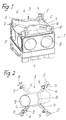
- FIG. 1 is a mounting box 1 for the concrete building installation with one hollow space for electrical Devices such as lights, boxes, clamps or the like electrotechnical Installation elements with side walls and Bottom wall 2 and an end wall on the the bottom wall 2 side shown.
- the one not visible in the drawings Front wall has one essentially circular installation opening, where especially with horizontal concrete formwork a mounting box 1 with the front wall on the Formwork can be attached or instead the mounting box 1 a counter bearing on the Formwork can be attached.
- the installation box 1 or the counter bearing can be via a Spacer with a second installation box be coupled, the end wall of the Formwork is oriented away. Since the Thickness of the corresponding wall of the producing concrete part different can be dimensioned is the spacer by preferably a large number of modules 3 formed.
- Each module 3 has several arms 4 on.
- upper and lower margins span two spaced apart from each other in module size Support levels, the first of which according to FIG. 1 in the installation position on the outside of the Bottom wall 2 of the installation box 1 rests and the second one on the bottom wall second installation box 1 or on one corresponding surface of a counter bearing or at the first support level, formed by the corresponding marginal edges of a second Module 3 is present. It can in this way several modules 3 arranged one above the other his. In this way, the length or Height of the spacer according to the height of module 3 can be set.
- the arms 4 of the module 3 are narrow Bridges with parallel upper and lower marginal edges formed the Spread or form support levels, with the Bridge height determines the module height.
- the web height the arm 4 is preferably about one Centimeter.
- the four arms 4 in Cross shape facing each other. At her free ends have 4 short arms Crossbars 5, the height of which is equal to Bridge height of arms 4 is so that they are over protrude none of the support levels. Basically the ends of the arms 4 are thus approximately T-shaped educated.
- the modules 3 are with each other or with the Bottom wall 2 of the installation box or surface of the corresponding counter bearing steckverbindbar. To do this, they point out as a connector Sockets 6 and Plug 7 on.
- the same kind of Connector means (6, 7) are on the Bottom wall 2 of the installation box in FIG. 3 seen.
- Each of the four arms 4 points equidistant from the center of the intersection of the Arms 4 a receptacle 6 and one Plug 7 on the coaxial to each other are directed.
- the receptacles and pins of the adjacent arms 4 oriented in opposite directions, so that the plug pins 7 alternately upwards or are directed below and the corresponding Analog sleeves 6 alternately downwards and directed above.
- the arms 4 of each module 3 close in the middle of module 3 to a one-piece Pipe clip 8 on one side of a radial open annular web is formed.
- the bridge height of this bridge is the same like the web height of the arms 4. Radial from this annular web, the arms 4 of the Module 3 onwards. Two arms connect to the open ends of the ring shape of the annular Dock. In this way it is possible an empty pipe in the serving as pipe clip 8 to introduce annular web radially and due to the elasticity of the material to clip.
- the empty pipe can for example to connect two kept at a distance by the modules Installation boxes serve.
- the corresponding module 3 can also, as from Figure 2 can be seen, several times at a distance from each other on an installation pipe 9 be clipped radially. Thereby forming two adjacent arms 4 of the module 3 supports, that are on a support surface, for example, the formwork surface, so that the installation pipe 9 at a distance of the corresponding support surface is held.
- Both the installation box 1 and the module 3 consists preferably of plastic.
- the module 3 can also be a top view have approximate U-shape, where preferably the U-shaped arms 4 at the free ends and in the corners corresponding sockets 6 and the Have plug 7.
- the Pipe clip 8 over a web with the base of the U-shape of the module 3 connected, the Opening the pipe clip 8 in the same direction Opening of the U shape runs.
- the Embodiment are at the leg ends the leg of the U-shape of the module 3 itself extending parallel to a support surface Support bars formed when in use as a spacer for an installation pipe analogous to the representation in FIG.
- a support element 10 is shown in FIGS. 5 and 6 shown which outside on the Bottom wall 2 of a mounting box 1 attachable, especially plug-attachable is.
- the support element 10 holds one Nut 11, the nut in the material of the plastic existing support element 10 is embedded and only one in the target position Bottom wall 2 open screw channel 12 has, whose mouth in the installation position bears against the bottom wall 2.
- the Bottom wall 2 is in the area of the mouth of the threaded shaft one into the Installation opening of the installation box 1 used screw hook or the like graspable, so such Screw hook in the screw nut 11 can be screwed in.
- Such a Screw hooks can be used for hanging, for example serve as a ceiling lamp.
- the support element 10 has two arms with sleeves 6 analog the training of modules 3 so that a corresponding plug connection with the analog trained bottom wall 2 of the installation box 1 is possible.
- the screw nut enclosed by the support element 10 11 arranged in the middle of the bottom wall 2.
- the screw nut 11 as threaded sleeve with polygon head formed
- the polygon head rotatably embedded in the material of the support element 10 is.
- This threaded sleeve is in one blind hole-like recess of the support element 10 embedded.
- the recess has an in Direction to the bottom wall 2 opposite Screw nut 11 or the threaded sleeve protruding mouth that widens conically is.
- the corresponding receptacles 6 and plug 7 as a push button Lanyard formed. Show the plug 7 at least one circumferential Snap bead and the sleeves 6 at least a corresponding circumferential locking groove or Locking edge on, so that in the mated position Snap bead in the groove or behind the Snap edge engages. This will create a particularly good position securing of the parts guaranteed to each other, which also when Concreting is effective and floating the parts prevented relative to each other.
- the alternately arranged Plug sleeves 6 and plug pins 7 are in the Corners of a square basic shape upwards and emanating from module 3 downwards or provided protruding, one appropriate orientation and arrangement of course also on the installation box 1 or other connector elements provided is.
- the distance is the Plug sleeves 6 of the first edge from each other and the distance between the plug pins 7 the second edge of each other like this voted that he was the diagonal distance two plug pins 7 or 6 sleeves Bottom wall 2 of a mounting box 1 or corresponds to the corresponding counter bearing.
- modules that are arranged upright, further modules in flat, not erect location put on and snap on.
- FIGS. 14 and 15 Training shown being between a than level formwork Concrete formwork, for example in Figure 15 arranged below the part shown and the front or bottom wall of the this attachable mounting box 1 directly on the surface of the formwork table attachable, forming a support surface Part 13 is provided, the support surface for the front wall or bottom wall of the Installation box 1, the plug pins and receptacles with which the end wall or Bottom wall over corresponding to her trained protruding plug and previous sockets are pluggable is.
- the relative bottom of part 13, which faces the formwork surface provided with adhesive pads 14 so that the part 13 at the predetermined position on the Formwork surface is adhesive fastened and then the installation box 1 or other necessary installation element with same training of rest and Connector means are applied can.
- FIG. 14 also shows that the plug pins 7 are slotted longitudinally, what manufacturing technology and in terms of Handling is advantageous.
- the invention is not based on that Embodiment limited, but in The scope of the disclosure is often variable.
Landscapes
- Engineering & Computer Science (AREA)
- Architecture (AREA)
- Civil Engineering (AREA)
- Structural Engineering (AREA)
- Forms Removed On Construction Sites Or Auxiliary Members Thereof (AREA)
Applications Claiming Priority (2)
| Application Number | Priority Date | Filing Date | Title |
|---|---|---|---|
| DE10035022 | 2000-07-19 | ||
| DE10035022A DE10035022A1 (de) | 2000-07-19 | 2000-07-19 | Anordnung von Einbaudosen für die Betonbauinstallation |
Publications (2)
| Publication Number | Publication Date |
|---|---|
| EP1174972A2 true EP1174972A2 (fr) | 2002-01-23 |
| EP1174972A3 EP1174972A3 (fr) | 2003-11-26 |
Family
ID=7649405
Family Applications (1)
| Application Number | Title | Priority Date | Filing Date |
|---|---|---|---|
| EP01115413A Withdrawn EP1174972A3 (fr) | 2000-07-19 | 2001-06-27 | Agencement de boítiers à affleurement pour installation en béton |
Country Status (2)
| Country | Link |
|---|---|
| EP (1) | EP1174972A3 (fr) |
| DE (1) | DE10035022A1 (fr) |
Cited By (1)
| Publication number | Priority date | Publication date | Assignee | Title |
|---|---|---|---|---|
| DE102020006452A1 (de) | 2020-10-20 | 2022-04-21 | Hanffaser Uckermark eG | Produkt eines Befestigungsadapters aus Pilzmyzel und Verwendung in einer Wanddämmung |
Citations (1)
| Publication number | Priority date | Publication date | Assignee | Title |
|---|---|---|---|---|
| BE828569A (fr) | 1974-05-03 | 1975-08-18 | Dispositif pour le positionnement de boitiers d'installation electrique dans des moules pour la fabrication de panneaux de construction prefabriques |
Family Cites Families (2)
| Publication number | Priority date | Publication date | Assignee | Title |
|---|---|---|---|---|
| FR1459216A (fr) * | 1965-09-28 | 1966-04-29 | Perfectionnements aux coffrets de raccordement et appareillages électriques analogues du type noyé | |
| FR2761208B1 (fr) * | 1997-03-19 | 1999-05-14 | Capri Codec Sa | Ensemble monobloc en plastique de maintien d'elements tels que des boitiers d'appareillage electrique entre des banches |
-
2000
- 2000-07-19 DE DE10035022A patent/DE10035022A1/de not_active Withdrawn
-
2001
- 2001-06-27 EP EP01115413A patent/EP1174972A3/fr not_active Withdrawn
Patent Citations (1)
| Publication number | Priority date | Publication date | Assignee | Title |
|---|---|---|---|---|
| BE828569A (fr) | 1974-05-03 | 1975-08-18 | Dispositif pour le positionnement de boitiers d'installation electrique dans des moules pour la fabrication de panneaux de construction prefabriques |
Cited By (1)
| Publication number | Priority date | Publication date | Assignee | Title |
|---|---|---|---|---|
| DE102020006452A1 (de) | 2020-10-20 | 2022-04-21 | Hanffaser Uckermark eG | Produkt eines Befestigungsadapters aus Pilzmyzel und Verwendung in einer Wanddämmung |
Also Published As
| Publication number | Publication date |
|---|---|
| EP1174972A3 (fr) | 2003-11-26 |
| DE10035022A1 (de) | 2002-01-31 |
Similar Documents
| Publication | Publication Date | Title |
|---|---|---|
| EP1244857A1 (fr) | Element cubique pour profiles et barre profilee associee | |
| DE10052577A1 (de) | Montagewinkel für Schienen | |
| EP0099972B1 (fr) | Elément d'assemblage pour plaques | |
| DE3620379C2 (fr) | ||
| DE4103957A1 (de) | Kabelkanal, wie installationskanal | |
| DE2005611C3 (de) | Lösbare Verbindung zweier Profilstabe mit U-förmigem Querschnitt | |
| EP1174972A2 (fr) | Agencement de boítiers à affleurement pour installation en béton | |
| EP1938904B1 (fr) | Dispositif de support pour le recouvrement de la cuve d'une fontaine ou d'un puits | |
| EP1134170B1 (fr) | Structure à assemblage modulaire pour des rayons de stockage | |
| DE69025714T2 (de) | Satz von sich ineinanderfügenden modulelementen zum bau von trennwänden | |
| CH586807A5 (en) | Nodal point connector for rod structures - has tubular holding socket and ring with seat for keyed linking plug | |
| EP3798379B1 (fr) | Système de profilé et système de réglage ainsi que procédé de fabrication d'un système de profilé et utilisation du système de profilé et/ou du système de réglage | |
| DE29501159U1 (de) | Verbindungskonstruktion | |
| DE3808145C2 (fr) | ||
| WO2013060470A1 (fr) | Dispositif porteur pour un dispositif meuble, en particulier pour un meuble de séparation | |
| DE19509398A1 (de) | Verbindungselement | |
| EP0696098B1 (fr) | Element intermédiaire de couplage pour dispositif de couplage pour canalisations de guidage de câbles | |
| EP0748020B1 (fr) | Support de plafond pour chemins de câbles ou cuvettes à câbles | |
| DE102022108542B3 (de) | Tragegestell zur tragenden Aufnahme eines Moduls, Einsatz für ein Tragegestell und Bausatz | |
| DE20312873U1 (de) | Kabelschacht | |
| DE4419589A1 (de) | Abstandshalter zur positionierten Befestigung einer Latte an einer Decke oder Wand | |
| DE29701879U1 (de) | Befestigungsvorrichtung für Stabmatten | |
| DE102010042976A1 (de) | Knotenbauteil für ein Gestell für einen Tisch, Gestell für einen Tisch sowie Tisch | |
| DE2942257A1 (de) | Doppelboden, bestehend aus bodenplatten und einer auf einem rohboden abgestuetzten unterkonstruktion | |
| DE20311022U1 (de) | Kabelkanal |
Legal Events
| Date | Code | Title | Description |
|---|---|---|---|
| PUAI | Public reference made under article 153(3) epc to a published international application that has entered the european phase |
Free format text: ORIGINAL CODE: 0009012 |
|
| AK | Designated contracting states |
Kind code of ref document: A2 Designated state(s): AT BE CH CY DE DK ES FI FR GB GR IE IT LI LU MC NL PT SE TR |
|
| AX | Request for extension of the european patent |
Free format text: AL;LT;LV;MK;RO;SI |
|
| 17P | Request for examination filed |
Effective date: 20020201 |
|
| PUAL | Search report despatched |
Free format text: ORIGINAL CODE: 0009013 |
|
| AK | Designated contracting states |
Kind code of ref document: A3 Designated state(s): AT BE CH CY DE DK ES FI FR GB GR IE IT LI LU MC NL PT SE TR |
|
| AX | Request for extension of the european patent |
Extension state: AL LT LV MK RO SI |
|
| RIC1 | Information provided on ipc code assigned before grant |
Ipc: 7H 02G 3/08 B Ipc: 7H 02G 3/12 A |
|
| AKX | Designation fees paid |
Designated state(s): AT BE CH FR LI NL |
|
| REG | Reference to a national code |
Ref country code: DE Ref legal event code: 8566 |
|
| 17Q | First examination report despatched |
Effective date: 20080225 |
|
| GRAP | Despatch of communication of intention to grant a patent |
Free format text: ORIGINAL CODE: EPIDOSNIGR1 |
|
| STAA | Information on the status of an ep patent application or granted ep patent |
Free format text: STATUS: THE APPLICATION IS DEEMED TO BE WITHDRAWN |
|
| 18D | Application deemed to be withdrawn |
Effective date: 20100529 |