EP1175162B1 - Gitterschmuckstück und herstellungsverfahren - Google Patents
Gitterschmuckstück und herstellungsverfahren Download PDFInfo
- Publication number
- EP1175162B1 EP1175162B1 EP00927607A EP00927607A EP1175162B1 EP 1175162 B1 EP1175162 B1 EP 1175162B1 EP 00927607 A EP00927607 A EP 00927607A EP 00927607 A EP00927607 A EP 00927607A EP 1175162 B1 EP1175162 B1 EP 1175162B1
- Authority
- EP
- European Patent Office
- Prior art keywords
- mesh
- jewel
- wire section
- pins
- latticework
- Prior art date
- Legal status (The legal status is an assumption and is not a legal conclusion. Google has not performed a legal analysis and makes no representation as to the accuracy of the status listed.)
- Expired - Lifetime
Links
- 239000010437 gem Substances 0.000 title claims abstract description 143
- 229910001751 gemstone Inorganic materials 0.000 title claims abstract description 135
- 238000000034 method Methods 0.000 title claims abstract description 39
- 238000004519 manufacturing process Methods 0.000 title claims abstract description 23
- 238000006073 displacement reaction Methods 0.000 claims abstract description 8
- 238000007493 shaping process Methods 0.000 claims description 52
- 238000005476 soldering Methods 0.000 claims description 26
- 238000003466 welding Methods 0.000 claims description 24
- 238000005266 casting Methods 0.000 claims description 11
- BASFCYQUMIYNBI-UHFFFAOYSA-N platinum Chemical compound [Pt] BASFCYQUMIYNBI-UHFFFAOYSA-N 0.000 claims description 11
- 238000010438 heat treatment Methods 0.000 claims description 7
- PCHJSUWPFVWCPO-UHFFFAOYSA-N gold Chemical compound [Au] PCHJSUWPFVWCPO-UHFFFAOYSA-N 0.000 claims description 6
- 239000010931 gold Substances 0.000 claims description 6
- 229910052737 gold Inorganic materials 0.000 claims description 6
- 239000000463 material Substances 0.000 claims description 5
- 229910052697 platinum Inorganic materials 0.000 claims description 5
- 239000004332 silver Substances 0.000 claims description 5
- 229910001200 Ferrotitanium Inorganic materials 0.000 claims description 4
- BQCADISMDOOEFD-UHFFFAOYSA-N Silver Chemical compound [Ag] BQCADISMDOOEFD-UHFFFAOYSA-N 0.000 claims description 4
- RTAQQCXQSZGOHL-UHFFFAOYSA-N Titanium Chemical compound [Ti] RTAQQCXQSZGOHL-UHFFFAOYSA-N 0.000 claims description 4
- 239000002904 solvent Substances 0.000 claims description 4
- 229910001220 stainless steel Inorganic materials 0.000 claims description 4
- 239000010935 stainless steel Substances 0.000 claims description 4
- 239000010936 titanium Substances 0.000 claims description 4
- 229910000971 Silver steel Inorganic materials 0.000 claims description 3
- 239000012815 thermoplastic material Substances 0.000 claims description 3
- 239000000853 adhesive Substances 0.000 claims description 2
- 230000001070 adhesive effect Effects 0.000 claims description 2
- 239000010970 precious metal Substances 0.000 description 10
- 229910052751 metal Inorganic materials 0.000 description 5
- 239000002184 metal Substances 0.000 description 5
- 239000000155 melt Substances 0.000 description 3
- 230000002035 prolonged effect Effects 0.000 description 3
- 230000000694 effects Effects 0.000 description 2
- 238000005498 polishing Methods 0.000 description 2
- 229910052709 silver Inorganic materials 0.000 description 2
- 238000005452 bending Methods 0.000 description 1
- ZPUCINDJVBIVPJ-LJISPDSOSA-N cocaine Chemical compound O([C@H]1C[C@@H]2CC[C@@H](N2C)[C@H]1C(=O)OC)C(=O)C1=CC=CC=C1 ZPUCINDJVBIVPJ-LJISPDSOSA-N 0.000 description 1
- 238000009792 diffusion process Methods 0.000 description 1
- 238000009826 distribution Methods 0.000 description 1
- 229910001254 electrum Inorganic materials 0.000 description 1
- 239000010940 green gold Substances 0.000 description 1
- 238000003754 machining Methods 0.000 description 1
- 238000002844 melting Methods 0.000 description 1
- 230000008018 melting Effects 0.000 description 1
- 150000002739 metals Chemical class 0.000 description 1
- 238000003825 pressing Methods 0.000 description 1
- 230000000284 resting effect Effects 0.000 description 1
- 229910001112 rose gold Inorganic materials 0.000 description 1
- 229910000679 solder Inorganic materials 0.000 description 1
- 239000007787 solid Substances 0.000 description 1
- 238000005482 strain hardening Methods 0.000 description 1
- 239000000126 substance Substances 0.000 description 1
- 239000010938 white gold Substances 0.000 description 1
- 229910000832 white gold Inorganic materials 0.000 description 1
Images






Classifications
-
- B—PERFORMING OPERATIONS; TRANSPORTING
- B21—MECHANICAL METAL-WORKING WITHOUT ESSENTIALLY REMOVING MATERIAL; PUNCHING METAL
- B21F—WORKING OR PROCESSING OF METAL WIRE
- B21F27/00—Making wire network, i.e. wire nets
- B21F27/12—Making special types or portions of network by methods or means specially adapted therefor
-
- A—HUMAN NECESSITIES
- A44—HABERDASHERY; JEWELLERY
- A44C—PERSONAL ADORNMENTS, e.g. JEWELLERY; COINS
- A44C27/00—Making jewellery or other personal adornments
-
- A—HUMAN NECESSITIES
- A44—HABERDASHERY; JEWELLERY
- A44C—PERSONAL ADORNMENTS, e.g. JEWELLERY; COINS
- A44C9/00—Finger-rings
-
- B—PERFORMING OPERATIONS; TRANSPORTING
- B21—MECHANICAL METAL-WORKING WITHOUT ESSENTIALLY REMOVING MATERIAL; PUNCHING METAL
- B21F—WORKING OR PROCESSING OF METAL WIRE
- B21F15/00—Connecting wire to wire or other metallic material or objects; Connecting parts by means of wire
- B21F15/02—Connecting wire to wire or other metallic material or objects; Connecting parts by means of wire wire with wire
- B21F15/06—Connecting wire to wire or other metallic material or objects; Connecting parts by means of wire wire with wire with additional connecting elements or material
-
- Y—GENERAL TAGGING OF NEW TECHNOLOGICAL DEVELOPMENTS; GENERAL TAGGING OF CROSS-SECTIONAL TECHNOLOGIES SPANNING OVER SEVERAL SECTIONS OF THE IPC; TECHNICAL SUBJECTS COVERED BY FORMER USPC CROSS-REFERENCE ART COLLECTIONS [XRACs] AND DIGESTS
- Y10—TECHNICAL SUBJECTS COVERED BY FORMER USPC
- Y10T—TECHNICAL SUBJECTS COVERED BY FORMER US CLASSIFICATION
- Y10T29/00—Metal working
- Y10T29/49—Method of mechanical manufacture
- Y10T29/49588—Jewelry or locket making
-
- Y—GENERAL TAGGING OF NEW TECHNOLOGICAL DEVELOPMENTS; GENERAL TAGGING OF CROSS-SECTIONAL TECHNOLOGIES SPANNING OVER SEVERAL SECTIONS OF THE IPC; TECHNICAL SUBJECTS COVERED BY FORMER USPC CROSS-REFERENCE ART COLLECTIONS [XRACs] AND DIGESTS
- Y10—TECHNICAL SUBJECTS COVERED BY FORMER USPC
- Y10T—TECHNICAL SUBJECTS COVERED BY FORMER US CLASSIFICATION
- Y10T29/00—Metal working
- Y10T29/49—Method of mechanical manufacture
- Y10T29/49588—Jewelry or locket making
- Y10T29/4959—Human adornment device making
- Y10T29/49593—Finger ring making
Definitions
- the invention relates to a mesh jewel and a method for manufacturing thereof.
- High purity precious metals for example platinum, gold or silver are generally used.
- High purity precious metals have a very high specific weight and they are very expensive, consequently large size jewels made of these metals are relatively heavy and expensive. Heavy jewels cause discomfort to people wearing them, and the high price does not allow a broader distribution of these jewels.
- relatively thick pure precious metal pieces are difficult to machine, i.e. that they are difficult to cut, bend and draw.
- a known solution for eliminating these problems in the jewel industry is the producing of so called mesh jewels, which comprise a mesh made of precious metal wire, arranged in a plane or along a three dimensional surface.
- This mesh enables the manufacturing of large size, attractive and yet low weight and not too expensive jewels.
- a mesh jewel and a method for its manufacturing are described for example in EP 0 495 100 A1.
- This known mesh jewel comprises a precious metal mesh arranged in a plane and fitted in a precious metal setting.
- the precious metal mesh is produced by laying at random a large number of metal wires bent in different shapes, followed by pressing, and then the metal wires are fixed to each other at the nodes.
- This fixing can be for example a diffusion joint assisted by heat treatment.
- the mesh is subjected to cold working, polishing and then it is placed into the setting.
- This known method is primarily suitable for producing meshes arranged in a plane, and the mesh may not have a complicated three dimensional shape.
- a further mesh jewel and a method for its manufacture are described in DE 29 19 912 A.
- This mesh jewel comprises node elements at crossings of the metal wire sections forming the mesh.
- the node elements are formed as balls having two through bores arranged in crosswise direction to each other through which the wire sections are inserted. These node elements are, however, difficult and costly to manufacture, and do not allow the crossing of more than two wire sections at a node.
- this known mesh jewel can not be manufactured with a dense mesh and with a sufficient rigidity.
- the invention is a mesh jewel comprising a mesh formed by at least one metallic wire section arranged along a mesh surface, wherein the mesh comprises nodes located at adjoining wire section parts of said at least one wire section, and wherein at least some of the nodes are formed with a node element fixing the adjoining wire section parts together.
- the mesh jewel has node elements comprising a pin arranged in cross direction to the mesh surface, wherein the wire section parts adjoining the pin are tangential to or bent on the pin, and wherein ends of the pin are closed by retaining means so as to prevent displacement of the adjoining wire section parts in an axial direction of the pin, said retaining means comprising a retaining element arranged at an end of the pin.
- the inventive mesh with the node elements results in a higher rigidity mesh jewel, which enables the manufacturing of larger and thus more decorative jewels with a low total weight.
- the higher rigidity further reduces the risk of permanent deformation when the jewel is in use.
- the node elements - by themselves or with decorative elements fixed to them - are suitable for creating a more attractive jewel.
- the retaining element can be formed for example as a flange, a ball having a bore, a setting holding a gem, or a soldered, welded, bonded or adhesive closing.
- the retaining elements can be fitted onto the end of the pin and fixed to the pin by soldering or welding, but they can be is formed integrally with the pin as well.
- the mesh can be made more rigid, if the wire section parts adjoining the pins of the node elements are fixed to the node elements by soldering or welding.
- the at least one wire section is tangential to or bent on the pins of the node elements, and passes by the pins at least twice from different directions.
- the mesh surface can be planar, a three-dimensional curved surface or a three-dimensional surface defined by planes.
- the mesh jewel comprises a latticework formed along the mesh surface, wherein the at least one wire section is arranged along a surface of the latticework and is attached to node elements fixed to lattice knots of the latticework.
- the latticework ensures the spatial fixing of the node elements. The fixing of the node elements is very important because in this way the wire section can be tightened on the pins of the node elements, thereby providing a more rigid structure.
- the latticework according to the invention allows the producing of a more rigid mesh jewel, which is larger and thus more decorative, with a low total weight. The higher rigidity also reduces the risk of the jewel suffering a permanent deformation while being worn.
- the mesh jewel comprises a rigid jewel body to which the mesh is attached by means of through holes or fixing node elements secured to the jewel body.
- the node elements can be fixed to the jewel body by means of distance rods, thereby resulting in a more rigid jewel.
- Parts of or the entire mesh jewel can be preferably formed integrally by casting.
- the material of the inventive mesh jewel can be platinum, gold, silver, titanium and/or stainless steel.
- the invention is a method for manufacturing a mesh jewel, comprising the steps of forming a mesh with at least one metallic wire section by arranging it along a mesh surface, wherein the mesh comprises nodes at adjoining wire section parts of said at least one wire section, and wherein at least some of the nodes are formed with a node element fixing the adjoining wire section parts together, characterised by arranging pins in cross direction to the mesh surface, and arranging said at least one wire section so as to pass tangentially to or bent on the pins and attaching ends of said at least one wire section to the mesh jewel, wherein ends of the pins are closed by retaining means so as to prevent displacement of adjoining wire section parts in an axial direction of the pin, said retaining means comprising retaining elements arranged at the ends of the pins.
- a mesh jewel with a higher rigidity can be manufactured simply and with a relatively low cost.
- the inventive method enables simple fitting of decorative elements along the surface of the mesh.
- a shaping piece having a surface corresponding to the mesh surface can be used.
- the shaping piece can be placed onto a rigid jewel body, and the at least one wire section can be arranged fixedly attached to the jewel body.
- the shaping piece is preferably made of a material completely removable by heat treating or by applying a solvent.
- the wire section can be guided in a way that it is adjusted to the surface of the shaping piece, and on the other the node elements are thereby spatially fixed. Fixing the node elements is very important because in this way the wire section can be tightened on the pins of the node elements, thereby ensuring a more rigid structure.
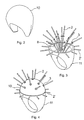
- the mesh jewel depicted in Fig. 1 is a ring which comprises a mesh made of one or more wire sections 4, and a rigid jewel body 11, to which the mesh is fixed.
- Nodes of the mesh are formed with node elements 1 arranged along a spherical surface, which node elements 1 comprise a pin 2 arranged crosswise to the spherical surface, a retaining element 3 arranged at an inner end of the pin 2, and a retaining element 5 arranged at an outer end of the pin 2.
- the retaining elements 3 and 5 are flanges, which are pulled on the ends of the pin and fixed there by welding or soldering.
- Node elements 1 are secured to the jewel body 11 by means of distance rods 8 in a way that the distance rods 8 are fitted into bores in jewel body 11, and fixed there by welding or soldering.
- the distance rods 8 serve as a firm support for the node elements 1, thereby increasing the rigidity of the mesh jewel.
- the distance rods 8 are not necessarily placed into bores, but they can also be welded or soldered to the wall of the jewel body 11.
- fixing node elements 1' On an external lateral surface of an upper flange part of the jewel body 11 there are fixing node elements 1' uniformly distributed in a circle, and they fix the mesh to the jewel body 11.
- Fixing pins 2' of the fixing node elements 1' are located in bores of jewel body 11, and fixed there by welding or soldering.
- the fixing node elements 1' comprise a retaining element 5' arranged at an outer end of the fixing pins 2', which retaining element is formed as a flange in the embodiment shown. This flange prevents the wire section parts adjoining the fixing pins 2' in coming off the retaining pin 2'. It is not necessary to locate the fixing pins 2' in bores, but they can also be welded or soldered to the wall of jewel body 11.
- the wire section 4 is arranged on the pins 2 of the node elements 1 located along the spherical surface in a manner that it touches the pins 2 without changing direction or is bent on them, and it returns to the pins 2 repeatedly from different directions, so that the pins 2 are surrounded by wire section 4.
- Parts of the wire section 4 touching the pins 2 and 2' may be fixed by laser spot welding or soldering to respective node elements 1 and 1'.
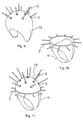
- a shaping piece 10 having a surface corresponding to a three dimensional mesh surface to be formed is produced.
- the shaping piece 10 is produced of a material that can be fully removed by heat treatment or by using a solvent, preferably wax, for example by carving or modelling.
- elements consisting of the retaining element 3 formed as a flange and the pin 2 are secured by means of the distance rods 8 to the jewel body 11, wherein the jewel body 11 is matched in shape to the shaping piece 10.
- the distance rods 8 may be formed as extensions of the pins 2, but they can also be designed as separate elements, fixed to the pins 2 by welding or soldering.
- bores located at equal spacing are formed to receive fixing pins 2', which are secured in the bores by welding or soldering.
- the spacing structure fitted on the jewel body 11 as described above is heated up and the shaping piece 10 is pulled onto the structure.
- bulges appearing on its surface are smoothed and so the interim phase shown in Fig. 4 is obtained.
- the shaping piece 10 fixes the pins 2 and this offers an especially advantageous hold for the spacing structure when arranging the wire section 4 and when tightening the same.
- a mesh matched to the surface of the shaping piece 10 is formed.
- the mesh is made of one or more wire sections 4, the thickness of which is preferably between 0.1 and 0.5 mm.
- one end of the wire section 4 is fixed to one of the pins 2 or 2'.
- the wire section 4 is preferably guided in a zigzag shape by bending it on pins 2, 2' as depicted in Fig.
- wire section 4 is repeatedly returned from different directions to the pin 2, 2' and it is thereby surrounded from several directions by the wire section 4.
- This guiding manner of the wire section 4 is advantageous for the aesthetic impact and also for the rigidity of the mesh jewel.
- the wire section 4 is tightened between the node elements 1 and 1' in a way that the wire section 4 rests on the surface of the shaping piece 10.
- the free end of the wire section 4 is fixed to one of the node elements 1. Thereby a mesh surface following the curved surface of the shaping piece 10 is obtained.
- Wire section parts 4a, 4b, 4c and 4d adjoining the node elements 1 can be fixed by welding or soldering to the node elements.
- retaining elements 5 formed as a flange are pulled onto the pins 2, protruding parts of the pins 2 are cut off, the retaining elements 5 are welded or soldered to the pins 2, and the external surface of the so formed node elements 1 is smoothed and polished.
- flange retaining elements 3 and 5 associated with the node elements 1 surround the wire section parts 4a, 4b, 4c and 4d bent on the pin 2.
- the fixing node elements 1' can be produced in an identical way with the difference that the wire section parts adjoining the pins 2' are supported by the external wall of the jewel body 11 and the by retaining elements 5'.
- the shaping piece 10 is removed by heat treatment or by using a chemical solvent. In this way the mesh jewel shown in Fig. 1 is created.
- through-holes formed in the jewel body 11 can be applied as well for fixing the mesh, when during the producing of the mesh, the wire section 4 is looped by guiding it through the through-holes.
- the wire section is not guided along a curved surface between the node elements, but along the shortest possible path in a straight way.
- distance rods are fixed to the jewel body by welding or soldering, and then the spacing structure is heated up and the shaping piece made of thermoplastic material is pulled onto the spacing structure.
- the shaping piece is necessary to be able to adjust the lengths of the distance rods according to the surface of the shaping piece, thereby arranging the node elements along the required surface.
- the node elements are formed at the ends of the distance rods adjusted to the surface of the shaping piece or they are secured to the distance rods.
- the shaping piece Prior to making the mesh, the shaping piece is removed and then the wire section is arranged along the shortest path possible between the node elements. This embodiment is advantageous, because the wire section between the nodes is not so easily loosed, if it is guided along the shortest path possible.
- Figs. 9 to 11 depict the steps of manufacturing a preferred embodiment of the invention, where distance rods are not used, and the node elements 1 are designed unsupported, they are only fixed by the mesh formed of wire section 4.
- This embodiment can be used advantageously when the mesh can be formed in a sufficiently rigid way to make sure that it is not subjected to permanent deformation even during prolonged use, and in case the mesh jewel is not subjected to any special mechanical load during use.
- the manufacturing of this embodiment also starts with the forming of shaping piece 10.
- elements comprising the retaining element 3 formed as a flange and the pin 2 are fixed to the surface of the shaping piece 10.
- the fixing is preferably implemented by bonding or by melting into the shaping piece 10.
- bores are formed on the external lateral surface of the upper flange part of the jewel body 11, into which the fixing pins 2' are placed an fixed there by welding or soldering.
- the shaping piece 10 is placed on the jewel body 11, thereby accomplishing the interim phase depicted in Fig. 11.
- the mesh consisting of the wire section 4 is prepared as described above.
- retaining elements 5 and 5' are pulled onto the pins 2 and 2', the protruding parts of the pins 2 and 2' are cut off, the retaining elements 5 and 5' are fixed by welding or soldering to the nodes, and then the external surface of the node elements 1 and 1' are smoothed and polished.
- the shaping piece 10 is removed as described above.
- Retaining elements 3 and 5 with the pin 2 can be preferably made integrally, for example by lathe machining.
- node elements 1 made integrally are fixed by distance rods to the jewel body or fitted on the surface of the shaping piece 10.
- the shaping piece can be immediately removed, because it is not necessary to close the pins.
- node elements 1 made integrally are advantageous, because a recessed setting can be formed in them for a gem on an external side of the retaining elements.
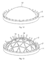
- Fig. 12 Manufacturing of another preferred embodiment of the mesh jewel according to the invention begins as depicted in Fig. 12 in a way that the rigid jewel body 11 is formed as an annular frame made of solid metal. In an upper flange section of the jewel body 11, equally spaced bores are formed in which fixing pins 2' are placed and fixed by welding or soldering. Next, a shaping piece 10 having a surface corresponding to a three dimensional mesh surface to be created is placed onto the jewel body 11. In the depicted preferred embodiment, the three dimensional mesh surface is a spherical surface.
- a latticework 12 resting on the surface of the shaping piece 10 is formed, and then in cross direction to the mesh surface, pins 2 are fixed to the lattice knots of the latticework 12.
- the shaping piece 10 is removed for example by heat treatment, thereby accomplishing the skeleton structure shown in Fig. 14.
- a mesh arranged along the latticework 12 is formed.
- the wire section 4 is tightened in a way that the wire section 4 follows the surface of the latticework 12. Thereby a mesh following the curved surface of the latticework 12 is obtained.
- the wire section parts passing by the node elements 1 or 1' may be fixed by welding or soldering to the node elements 1 or 1'.
- the mesh jewel may also be manufactured by employing a casting method known per se.
- a casting method known per se For example it is possible to produce the rigid jewel body 11 with the fixing pins 2' and the latticework 12 with the pins 2 integrally by casting. To this end, of course it is necessary to form a master pattern in a way described above, to produce the mould in a manner known per se.
- the workpiece produced by casting can then be subjected to a deburring and/or polishing method known per se, followed by the forming of the mesh on it, and the closing of the ends of the pins 2 and 2'.
- the total mesh jewel i.e. the rigid jewel body 11 with the fixing pins 2', the latticework 12 with the pins 2 and the mesh and the closings can be produced integrally by casting.
- some of the openings of the latticework 12 can be covered by embossed or flat plates.
- the plates can be fixed by soldering or welding on the latticework 12, but they can also be produced by the above casting method.
- the openings can for example be covered in a chessboard pattern.
- the latticework 12 follows a pattern consisting of equilateral triangles, but it can also be designed in a square, hexagonal or random pattern.
- Fig. 16 shows a partial sectional front view of the mesh jewel made by the method shown in Figs. 12 to 15.
- the nodes of the latticework of the mesh jewel are formed with node elements 1 arranged along the spherical surface as described above, which node elements 1 comprise the pin 2 - arranged crosswise to the spherical surface - and the retaining element arranged on the outer end of the pin 2.
- the retaining elements have a ball shape fitted with a bore and they are pulled onto the ends of the pins, where they are fixed by welding or soldering.
- the latticework 12 serves as a firm support for the node elements 1, thereby increasing the rigidity of the mesh jewel.
- the fixing node elements 1' comprise retaining elements arranged at an outer end of the fixing pins 2', which retaining elements are designed in the embodiment depicted as balls fitted with a bore. These retaining elements prevent the wire section parts passing by the fixing pins 2' in coming off the fixing pins 2'. It is not necessary to fit the fixing pins 2' in bores, but they may also be welded or soldered to the wall of the jewel body 11.
- the wire section 4 is arranged on the pins 2 of the node elements 1 arranged along the surface of the latticework 12 and on the pins 2' in a way that it is in contact without changing direction or is bent on the pins 2 and 2', repeatedly returns from different directions to and surrounds each pin 2 and 2'.
- the wire section parts in contact with pins 2 and 2' may be fixed by laser spot welding or soldering to the node elements 1 and 1'.
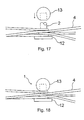
- Figs. 17 and 18 the steps of manufacturing a node element 1 as per Fig. 16 can be seen.
- the node element 1 first the cylindrical pin 2 is fixed by welding or soldering to the latticework 12. After arranging the wire sections 4 according to the description above, the protruding part of the pin 2 is cut to size and the free end of the pin 2 is closed by a ball shaped retaining element 13. In the ball shaped retaining element 13 a bore is formed, which is pulled onto the free end of the pin 2, and then the retaining element 13 is fixed by welding or soldering.
- the node element 1 shown in Fig. 19 is closed by a soldered closing 9.
- the solder runs into and between the wire section parts bent around the pin 2, and secures the wire section parts to the pin 2 and to the latticework 12.
- the melt generated in the course of soldering is then removed.
- a different joint may also be applied, for example a welded or bonded joint.
- the free end of the pin 2 is closed with a retaining element 6 formed as a setting, wherein the latticework 12 and the setting surround the wire section parts adjoining the pin 2.
- the setting preferably receives a gem 7.
- the setting which further improves the aesthetic appearance of the mesh jewel, is also fixed by welding or soldering to the pin 2.
- the mesh jewel according to the invention is not limited to the embodiments described above, but may also be formed in a different way. It is possible for example to create a mesh jewel without a rigid jewel body, when the mesh preferably forms a closed body, for example a globe or a spatial heart shape.
- the pins fitted with retaining elements are fixed to the surface of the shaping piece, the mesh is formed on the surface of the shaping piece, the free ends of the pins are closed and then the shaping piece is removed.
- a latticework is formed on the surface of the shaping piece, pins are fixed to the lattice knots of the latticework, the shaping piece is removed, the at least one wire section is arranged as described above, and the free ends of the pins are closed.
- the casting step described above can be applied of course in the case of these embodiments as well.
- the mesh jewel can be designed in a sufficiently rigid manner so that it does not suffer permanent deformation in the course of prolonged use, and if the mesh jewel is not subjected to any special mechanical load while being worn.
- Such a mesh jewel can be for example an ear-ring, a pendant etc.
- the retaining elements may not only be designed as a flange, ball or setting.
- the end of the pin can be melted, thereby forming a melt sphere at the end, and then the melt sphere is cooled.
- the retaining element so designed can sufficiently prevent the displacement of the wire section parts passing by the pin in the axial direction of the pin.
- the mesh, the nodes and in the given case the jewel body may be made of the same precious metal, but if a varied colour effect is to be accomplished, different precious metals can be applied for each element.
- a platinum wire can be soldered with pure gold.
- the material of the mesh jewel can be for example silver, white gold, green gold, red gold, pure gold, platinum, titanium or stainless steel.
Landscapes
- Engineering & Computer Science (AREA)
- Mechanical Engineering (AREA)
- Manufacturing & Machinery (AREA)
- Adornments (AREA)
Claims (38)
- Geflecht-Schmuckstück mit einem Geflecht, das durch zumindest einen entlang einer Geflechtoberfläche angeordneten metallischen Drahtabschnitt gebildet ist, wobei das Geflecht Knoten aufweist, die sich bei benachbarten Drahtabschnittteilen des zumindest einen Drahtabschnittes befinden, und wobei zumindest einige der Knoten mit einem Knotenelement gebildet sind, das die benachbarten Drahtabschnittteile aneinander befestigt, dadurch gekennzeichnet, dass Knotenelemente (1) vorhanden sind, die einen Stift (2) aufweisen, der in Querrichtung zu der Geflechtoberfläche angeordnet ist, wobei die zu dem Stift (2) benachbarten Drahtabschnittteile (4a, 4b, 4c, 4d) tangential zu dem Stift (2) oder um ihn gebogen sind und wobei Enden des Stiftes (2) durch ein Haltemittel geschlossen sind, um eine Verlagerung der benachbarten Drahtabschnittteile (4a, 4b, 4c, 4d) in einer axialen Richtung des Stiftes (2) zu verhindern, wobei das Haltemittel ein an einem Ende des Stiftes (2) angeordnetes Halteelement (3, 5, 6, 9, 13) umfasst.
- Geflecht-Schmuckstück nach Anspruch 1, dadurch gekennzeichnet, dass es Halteelemente (3, 5) umfasst, die als Flansche ausgebildet sind.
- Geflecht-Schmuckstück nach Anspruch 1, dadurch gekennzeichnet, dass es Halteelemente (13) umfasst, die als Kugeln mit einer Bohrung ausgebildet sind.
- Geflecht-Schmuckstück nach Anspruch 1, dadurch gekennzeichnet, dass es Halteelemente (6) umfasst, die als eine einen Edelstein (7) haltende Fassung ausgebildet sind.
- Geflecht-Schmuckstück nach einem der Ansprüche 2 bis 4, dadurch gekennzeichnet, dass die Halteelemente (3, 5, 6, 13) an dem Ende des Stiftes (2) durch Löten oder Schweißen befestigt sind.
- Geflecht-Schmuckstück nach einem der Ansprüche 2 bis 4, dadurch gekennzeichnet, dass die Halteelemente (3, 5, 6, 13) integral mit dem Stift (2) gebildet sind.
- Geflecht-Schmuckstück nach Anspruch 1, dadurch gekennzeichnet, dass es Halteelemente umfasst, die als ein gelöteter, geschweißter, geklebter oder adhäsiver Verschluss (9) ausgebildet sind.
- Geflecht-Schmuckstück nach Anspruch 1, dadurch gekennzeichnet, dass die zu den Knotenelementen (1) benachbarten Drahtabschnittteile (4a, 4b, 4c, 4d) durch Löten oder Schweißen an den Knotenelementen (1) befestigt sind.
- Geflecht-Schmuckstück nach Anspruch 1, dadurch gekennzeichnet, dass es ein entlang der Geflechtoberfläche gebildetes Gitterwerk (12) umfasst, wobei der zumindest eine Drahtabschnitt (4) entlang einer Oberfläche des Gitterwerkes (12) angeordnet und an Knotenelementen (1) befestigt ist, die an Gitterknoten des Gitterwerkes (12) befestigt sind.
- Geflecht-Schmuckstück nach Anspruch 1, dadurch gekennzeichnet, dass es einen starren Schmuckstück-Körper (11) umfasst, an welchem das Geflecht befestigt ist.
- Geflecht-Schmuckstück nach Anspruch 10, dadurch gekennzeichnet, dass in dem Schmuckstück-Körper (11) Durchgangslöcher gebildet sind und das Geflecht an dem Schmuckstück-Körper (11) durch Durchführen des zumindest einen Drahtabschnittes durch die Durchgangslöcher befestigt ist.
- Geflecht-Schmuckstück nach Anspruch 10, dadurch gekennzeichnet, dass das Geflecht an dem Schmuckstück-Körper (11) durch Befestigungs-Knotenelemente (1') befestigt ist, die an dem Schmuckstück-Körper (11) mit ihren entsprechenden Stiften (2') befestigt sind.
- Geflecht-Schmuckstück nach Anspruch 10, dadurch gekennzeichnet, dass die Knotenelemente (1) an dem Schmuckstück-Körper (11) mittels Abstandsstäben (8) befestigt sind.
- Geflecht-Schmuckstück nach Anspruch 10, dadurch gekennzeichnet, dass es ein Gitterwerk (12) umfasst, das an dem Schmuckstück-Körper (11) befestigt und entlang der Geflechtoberfläche gebildet ist, wobei der zumindest eine Drahtabschnitt (4) entlang einer Oberfläche des Gitterwerkes (12) angeordnet und an Knotenelementen (1) befestigt ist, die an Gitterknoten des Gitterwerkes (12) befestigt sind.
- Geflecht-Schmuckstück nach Anspruch 1, dadurch gekennzeichnet, dass zumindest ein Teil davon integral durch Gießen gebildet ist.
- Geflecht-Schmuckstück nach Anspruch 1, dadurch gekennzeichnet, dass es aus Platin, Gold, Silber, Titan und/oder rostfreiem Stahl gebildet ist.
- Verfahren zum Herstellen eines Geflecht-Schmuckstückes, bei welchem ein Geflecht mit zumindest einem metallischen Drahtabschnitt gebildet wird, indem er entlang einer Geflechtoberfläche angeordnet wird, wobei das Geflecht an benachbarten Drahtabschnittteilen des zumindest einen Drahtabschnittes Knoten aufweist und wobei zumindest einige der Knoten mit einem Knotenelement gebildet werden, das die benachbarten Drahtabschnittteile aneinander befestigt, dadurch gekennzeichnet, dass Stifte in Querrichtung zu der Geflechtoberfläche angeordnet werden und dass der zumindest eine Drahtabschnitt so angeordnet wird, dass er tangential zu den Stiften oder um sie gebogen verläuft, und dass Enden des zumindest einen Drahtabschnittes an dem Geflecht-Schmuckstück befestigt werden, wobei Enden der Stifte durch Haltemittel geschlossen werden, um eine Verlagerung benachbarter Drahtabschnittteile in einer axialen Richtung des Stiftes zu verhindern, wobei die Haltemittel an den Enden der Stifte angeordnete Halteelemente umfassen.
- Verfahren nach Anspruch 17, dadurch gekennzeichnet, dass ein Formgebungsteil mit einer der Geflechtoberfläche entsprechenden Oberfläche gebildet wird, dass entlang der Oberfläche des Formgebungsteils Stifte befestigt werden, die zumindest an ihren dem Formgebungsteil zugewandten Enden mit entsprechenden Halteelementen ausgestattet sind, dass der zumindest eine Drahtabschnitt entlang der Oberfläche des Formgebungsteils angeordnet wird und dass das Formgebungsteil entfernt wird.
- Verfahren nach Anspruch 18, dadurch gekennzeichnet, dass die entlang der Oberfläche des Formgebungsteils befestigten Stifte nur an ihren dem Formgebungsteil zugewandten Enden mit entsprechenden Halteelementen ausgestattet sind und dass nach dem Anordnen des zumindest einen Drahtabschnittes freie Enden der Stifte durch weitere Halteelemente oder Verschlüsse geschlossen werden.
- Verfahren nach Anspruch 18, dadurch gekennzeichnet, dass die entlang der Oberfläche des Formgebungsteils befestigten Stifte an ihren beiden Enden mit Halteelementen ausgestattet sind.
- Verfahren nach Anspruch 18, dadurch gekennzeichnet, dass die an den Stiften anstoßenden Drahtabschnittteile an den Stiften durch Löten oder Schweißen befestigt werden.
- Verfahren nach Anspruch 18, dadurch gekennzeichnet, dass das Formgebungsteil auf einem starren Schmuckstück-Körper angeordnet wird und dass der zumindest eine Drahtabschnitt fest an dem Schmuckstück-Körper befestigt angeordnet wird.
- Verfahren nach Anspruch 22, dadurch gekennzeichnet, dass Durchgangslöcher in dem Schmuckstück-Körper gebildet werden und dass der zumindest eine Drahtabschnitt an dem Schmuckstück-Körper befestigt wird, indem er durch die Durchgangslöcher geführt wird.
- Verfahren nach Anspruch 22, dadurch gekennzeichnet, dass an dem Schmuckstück-Körper befestigte Befestigungsstifte gebildet werden und dass der zumindest eine Drahtabschnitt an dem Schmuckstück-Körper mittels der Befestigungsstifte befestigt wird.
- Verfahren nach Anspruch 22, dadurch gekennzeichnet, dass eine Schmuckstück-Struktur erzeugt wird, indem die Stifte mit den Halteelementen mittels Abstandsstäben an dem Schmuckstück-Körper befestigt werden und dass nach dem Erwärmen der Schmuckstück-Struktur das aus einem thermoplastischen Material hergestellte Formgebungsteil auf die Schmuckstück-Struktur gezogen wird.
- Verfahren nach Anspruch 22, dadurch gekennzeichnet, dass eine Schmuckstück-Struktur erzeugt wird, indem Abstandsstäbe an dem Schmuckstück-Körper befestigt werden, dass nach dem Erwärmen der Schmuckstück-Struktur das aus einem thermoplastischen Material hergestellte Formgebungsteil auf die Schmuckstück-Struktur gezogen wird, dass freie Enden der Abstandsstäbe entsprechend der Oberfläche des Formgebungsteils eingestellt werden and dass die Stifte mit den Halteelementen an den freien Enden der Abstandsstäbe gebildet werden.
- Verfahren nach Anspruch 26, dadurch gekennzeichnet, dass das Formgebungsteil entfernt wird, bevor der zumindest eine Drahtabschnitt angeordnet wird, und dass der zumindest eine Drahtabschnitt entlang des kürzesten Weges zwischen den Stiften angeordnet wird.
- Verfahren nach Anspruch 25 oder Anspruch 26, dadurch gekennzeichnet, dass die Schmuckstück-Struktur integral durch Gießen gebildet wird.
- Verfahren nach Anspruch 17, dadurch gekennzeichnet, dass ein Gitterwerk mit einer dreidimensionalen Oberfläche erzeugt wird, die der Geflechtoberfläche entspricht, und dass es mit Stiften ausgestattet wird, die an Gitterknoten des Gitterwerkes befestigt sinnd, und dass der zumindest eine Drahtabschnitt entlang der Oberfläche des Gitterwerkes and mittels der Stifte fest mit dem Gitterwerk verbunden angeordnet wird.
- Verfahren nach Anspruch 29, dadurch gekennzeichnet, dass ein Formgebungsteil mit einer dreidimensionalen Oberfläche erzeugt wird, die der Geflechtoberfläche entspricht, dass das Gitterwerk entlang der Oberfläche des Formgebungsteils gebildet wird, dass die Stifte an den Gitterknoten des Gitterwerkes befestigt werden und dass das Formgebungsteil entfernt wird.
- Verfahren nach Anspruch 29, dadurch gekennzeichnet, dass das Gitterwerk mit den an den Gitterknoten befestigten Stiften integral durch Gießen gebildet wird.
- Verfahren nach Anspruch 30, dadurch gekennzeichnet, dass die Halteelemente nachdem Anordnen des zumindest einen Drahtabschnittes an den freien Enden der Stifte durch Löten oder Schweißen befestigt werden.
- Verfahren nach Anspruch 30, dadurch gekennzeichnet, dass die Haltemittel integral mit den Stiften gehildet werden.
- Verfahren nach Anspruch 30, dadurch gekennzeichnet, dass das Gitterwerk fast an einem Schmuckstück-Körper befestigt gebildet wird.
- Verfahren nach Anspruch 34, dadurch gekennzeichnet, dass Befestigungsstifte an dem Schmuckstück-Körper befestigt werden und dass der zumindest eine Drahtabschnitt an dem Schmuckstück-Körper durch die Befestigungsstifte fest befestigt angeordnet wird.
- Verfahren nach Anspruch 35, dadurch gekennzeichnet, dass der Schmuckstück-Körper, das Gitterwerk mit den an den Gitterknoten befestigten Stiften und die Befestigungsstifte integral durch Gießen gebildet werden.
- Verfahren nach Anspruch 17, dadurch gekennzeichnet, dass das Geflecht-Schmuckstück aus Platin, Gold, Silber, Titan und/oder rostfreiem Stahl gebildet wird.
- Verfahren nach Anspruch 18, dadurch gekennzeichnet, dass das Formgebungsteil aus einem Material gebildet ist, das durch eine Wärmebehandlung oder durch Anwenden eines Lösungsmittels vollständig entfernbar ist.
Applications Claiming Priority (5)
| Application Number | Priority Date | Filing Date | Title |
|---|---|---|---|
| HU9901406A HU220743B1 (hu) | 1999-04-28 | 1999-04-28 | Hálóékszer és eljárás annak előállítására |
| HU9901406 | 1999-04-28 | ||
| HU9903394 | 1999-10-06 | ||
| HU9903394A HU222512B1 (hu) | 1999-10-06 | 1999-10-06 | Hálóékszer és eljárás annak előállítására |
| PCT/HU2000/000037 WO2000065949A1 (en) | 1999-04-28 | 2000-04-28 | Mesh jewel and method for manufacturing thereof |
Publications (2)
| Publication Number | Publication Date |
|---|---|
| EP1175162A1 EP1175162A1 (de) | 2002-01-30 |
| EP1175162B1 true EP1175162B1 (de) | 2003-04-16 |
Family
ID=89999572
Family Applications (1)
| Application Number | Title | Priority Date | Filing Date |
|---|---|---|---|
| EP00927607A Expired - Lifetime EP1175162B1 (de) | 1999-04-28 | 2000-04-28 | Gitterschmuckstück und herstellungsverfahren |
Country Status (8)
| Country | Link |
|---|---|
| US (2) | US6766659B1 (de) |
| EP (1) | EP1175162B1 (de) |
| JP (1) | JP2002542853A (de) |
| AT (1) | ATE237245T1 (de) |
| AU (1) | AU4599700A (de) |
| DE (1) | DE60002190T2 (de) |
| ES (1) | ES2193074T3 (de) |
| WO (1) | WO2000065949A1 (de) |
Families Citing this family (13)
| Publication number | Priority date | Publication date | Assignee | Title |
|---|---|---|---|---|
| BE1015289A3 (nl) * | 2002-10-07 | 2005-01-11 | Quijo Peter | Juweel, werkwijze voor het vervaardigen ervan en gereedschap hierbij aangewend. |
| USD505878S1 (en) * | 2003-10-24 | 2005-06-07 | Universal Pacific Diamonds & Jewelry, Llc | Ring |
| USD514468S1 (en) * | 2004-06-09 | 2006-02-07 | Marthe Roberts-Shea | Ring |
| USD543130S1 (en) * | 2005-04-22 | 2007-05-22 | Cartier International, B.V. | Pendant |
| USD549607S1 (en) * | 2005-09-09 | 2007-08-28 | Cartier Creation Studio Sa | Earring |
| KR100556819B1 (ko) | 2005-11-29 | 2006-03-10 | 주식회사 케이에스 주얼리 | 가요성 금속 와이어를 사용하여 악세서리를 제조하는 방법및 그 방법으로 제조된 악세서리 |
| KR20070076135A (ko) * | 2006-01-18 | 2007-07-24 | 주식회사 케이에스 주얼리 | 금속 골격체와 와이어를 이용한 악세서리 제조 방법 및 그방법으로 제조된 악세서리 |
| USD611868S1 (en) * | 2007-01-08 | 2010-03-16 | Altmann Casting Ag | Jewelry |
| USD597882S1 (en) * | 2008-03-25 | 2009-08-11 | Hermes Sellier (Societe Par Actions Simplifiee) | Ring |
| USD586251S1 (en) * | 2008-04-16 | 2009-02-10 | Courtney Jill Walker | Wire wrapped ring |
| IT1397682B1 (it) * | 2010-01-15 | 2013-01-18 | C A Oro S N C Di Caoduro Andrea & Carlo | Procedimento per l'ottenimento di articoli ornamentali di oreficeria, gioielleria e/o simili ed articolo ornamentale ottenuto tramite tale procedimento |
| USD777597S1 (en) * | 2015-08-03 | 2017-01-31 | Cartier International Ag | Ring |
| WO2020041459A1 (en) * | 2018-08-21 | 2020-02-27 | Michal Kadar Llc D/B/A Cadar | Jewelry coil |
Family Cites Families (15)
| Publication number | Priority date | Publication date | Assignee | Title |
|---|---|---|---|---|
| US2135333A (en) * | 1937-11-09 | 1938-11-01 | Audubon Wire Cloth Corp | Woven wire fabric |
| US2258413A (en) * | 1941-06-13 | 1941-10-07 | Koven Marc | Gem setting |
| US2451749A (en) * | 1946-05-31 | 1948-10-19 | Kreisler Mfg Corp Jacques | Bracelet or the like and method of making the same |
| US2577584A (en) * | 1946-08-12 | 1951-12-04 | Swarovski Glasfabrik Und Tyrol | Manufacture of meshlike ornamental articles |
| GB1438537A (en) * | 1973-04-10 | 1976-06-09 | Charman P | Thread or the like designs drawings pictures patterns and creation |
| JPS548142B2 (de) * | 1974-05-18 | 1979-04-12 | ||
| US4332501A (en) * | 1978-08-03 | 1982-06-01 | General Dynamics Corporation | Structural node for large space structures |
| DE2919912A1 (de) * | 1979-05-17 | 1980-08-14 | Gabriele Adlassnig | Verfahren und vorrichtung zur herstellung von schmuckstuecken und danach hergestellte schmuckstuecke |
| JPS60184440A (ja) * | 1984-03-01 | 1985-09-19 | Manabu Kiuchi | メツシユバンド |
| DE3424206A1 (de) * | 1984-06-30 | 1986-01-23 | Fico Fischer & Co Maschinenbau GmbH, 7537 Remchingen | Verfahren zum herstellen von aus duennen metallischem draht, band oder dergleichen bestehenden ringen, ketten, geflechten oder dergleichen |
| WO1992002157A1 (fr) * | 1990-07-31 | 1992-02-20 | Mitsubishi Materials Corporation | Structure a mailles metalliques pour articles de parure et procede de fabrication de cette structure |
| US5230631A (en) * | 1991-08-07 | 1993-07-27 | John Halmaghi | Educational amusement device and jewelry item |
| US5224959A (en) * | 1992-02-18 | 1993-07-06 | Kasper Thomas A | Skeleton ball |
| DE4317210C2 (de) * | 1993-05-21 | 1998-10-15 | Norbert Muerrle | Halbzeug zur Herstellung von Schmuck und Verfahren zu dessen Bearbeitung |
| US5918438A (en) * | 1997-04-15 | 1999-07-06 | South; David B. | Dome type building and method of making same |
-
2000
- 2000-04-28 DE DE60002190T patent/DE60002190T2/de not_active Expired - Fee Related
- 2000-04-28 AT AT00927607T patent/ATE237245T1/de not_active IP Right Cessation
- 2000-04-28 AU AU45997/00A patent/AU4599700A/en not_active Abandoned
- 2000-04-28 WO PCT/HU2000/000037 patent/WO2000065949A1/en not_active Ceased
- 2000-04-28 US US10/030,755 patent/US6766659B1/en not_active Expired - Fee Related
- 2000-04-28 ES ES00927607T patent/ES2193074T3/es not_active Expired - Lifetime
- 2000-04-28 JP JP2000614842A patent/JP2002542853A/ja active Pending
- 2000-04-28 EP EP00927607A patent/EP1175162B1/de not_active Expired - Lifetime
-
2003
- 2003-09-09 US US10/658,587 patent/US20040078975A1/en not_active Abandoned
Also Published As
| Publication number | Publication date |
|---|---|
| WO2000065949A1 (en) | 2000-11-09 |
| DE60002190D1 (de) | 2003-05-22 |
| EP1175162A1 (de) | 2002-01-30 |
| JP2002542853A (ja) | 2002-12-17 |
| DE60002190T2 (de) | 2003-12-18 |
| US20040078975A1 (en) | 2004-04-29 |
| ATE237245T1 (de) | 2003-05-15 |
| AU4599700A (en) | 2000-11-17 |
| US6766659B1 (en) | 2004-07-27 |
| ES2193074T3 (es) | 2003-11-01 |
Similar Documents
| Publication | Publication Date | Title |
|---|---|---|
| US6766659B1 (en) | Mesh jewel and method for manufacturing thereof | |
| KR102578504B1 (ko) | 피어싱 기술, 이를 위한 귀걸이, 및 그 제조 및 사용 방법 | |
| JP4520996B2 (ja) | 宝飾品のための可撓性連結具及び製造方法 | |
| US6412304B1 (en) | Jewelry | |
| JP7461186B2 (ja) | 環状装飾具およびその製造方法 | |
| US20020166339A1 (en) | Jewelry, jewelry design and method and apparatus therefor | |
| JPS58105707A (ja) | 互にピン結合されたリンクから構成された金属腕輪とその製造方法 | |
| US5148689A (en) | Hinge for a necklace | |
| WO2000057743A2 (en) | Setting of gemstones | |
| KR102453936B1 (ko) | 볼륨감을 갖는 입체 펜던트 제조방법 | |
| JP7278664B1 (ja) | 石枠およびその製造方法 | |
| KR100392883B1 (ko) | 파이프를 이용한 신변장신구의 제조방법 및 그 신변장신구 | |
| HU220743B1 (hu) | Hálóékszer és eljárás annak előállítására | |
| KR101485406B1 (ko) | 청각적 효과를 나타내는 장신구 | |
| HU222512B1 (hu) | Hálóékszer és eljárás annak előállítására | |
| US5581884A (en) | Method of attaching an ornamental setting to an ornament | |
| KR960006921B1 (ko) | 시계밴드의 금판 접착방법 | |
| CN112137258B (zh) | 用于制造中空管状首饰的系统和方法 | |
| EP1068815A2 (de) | Zierelement und Verfahren zu dessen Herstellung | |
| KR100490282B1 (ko) | 장신용 체인의 제조방법 | |
| JP3084579U (ja) | 装身具 | |
| JPH07289321A (ja) | 装飾体の製造方法 | |
| KR20020019324A (ko) | 금망사슬제 장식 액세서리용 구상 의장소자 및 그 제조방법 | |
| JPS633719B2 (de) | ||
| KR100359478B1 (ko) | 장신구용 금자석의 제조방법 및 그 물품 |
Legal Events
| Date | Code | Title | Description |
|---|---|---|---|
| PUAI | Public reference made under article 153(3) epc to a published international application that has entered the european phase |
Free format text: ORIGINAL CODE: 0009012 |
|
| 17P | Request for examination filed |
Effective date: 20011127 |
|
| AK | Designated contracting states |
Kind code of ref document: A1 Designated state(s): AT BE CH CY DE DK ES FI FR GB GR IE IT LI LU MC NL PT SE |
|
| AX | Request for extension of the european patent |
Free format text: AL;LT;LV;MK;RO;SI |
|
| GRAH | Despatch of communication of intention to grant a patent |
Free format text: ORIGINAL CODE: EPIDOS IGRA |
|
| GRAH | Despatch of communication of intention to grant a patent |
Free format text: ORIGINAL CODE: EPIDOS IGRA |
|
| GRAA | (expected) grant |
Free format text: ORIGINAL CODE: 0009210 |
|
| AK | Designated contracting states |
Designated state(s): AT BE CH CY DE DK ES FI FR GB GR IE IT LI LU MC NL PT SE |
|
| PG25 | Lapsed in a contracting state [announced via postgrant information from national office to epo] |
Ref country code: NL Free format text: LAPSE BECAUSE OF FAILURE TO SUBMIT A TRANSLATION OF THE DESCRIPTION OR TO PAY THE FEE WITHIN THE PRESCRIBED TIME-LIMIT Effective date: 20030416 Ref country code: FI Free format text: LAPSE BECAUSE OF FAILURE TO SUBMIT A TRANSLATION OF THE DESCRIPTION OR TO PAY THE FEE WITHIN THE PRESCRIBED TIME-LIMIT Effective date: 20030416 Ref country code: BE Free format text: LAPSE BECAUSE OF FAILURE TO SUBMIT A TRANSLATION OF THE DESCRIPTION OR TO PAY THE FEE WITHIN THE PRESCRIBED TIME-LIMIT Effective date: 20030416 |
|
| REG | Reference to a national code |
Ref country code: GB Ref legal event code: FG4D |
|
| PG25 | Lapsed in a contracting state [announced via postgrant information from national office to epo] |
Ref country code: LU Free format text: LAPSE BECAUSE OF NON-PAYMENT OF DUE FEES Effective date: 20030428 Ref country code: IE Free format text: LAPSE BECAUSE OF NON-PAYMENT OF DUE FEES Effective date: 20030428 Ref country code: CY Free format text: LAPSE BECAUSE OF FAILURE TO SUBMIT A TRANSLATION OF THE DESCRIPTION OR TO PAY THE FEE WITHIN THE PRESCRIBED TIME-LIMIT Effective date: 20030428 |
|
| PG25 | Lapsed in a contracting state [announced via postgrant information from national office to epo] |
Ref country code: MC Free format text: LAPSE BECAUSE OF NON-PAYMENT OF DUE FEES Effective date: 20030430 |
|
| REG | Reference to a national code |
Ref country code: CH Ref legal event code: EP |
|
| REF | Corresponds to: |
Ref document number: 60002190 Country of ref document: DE Date of ref document: 20030522 Kind code of ref document: P |
|
| REG | Reference to a national code |
Ref country code: IE Ref legal event code: FG4D |
|
| REG | Reference to a national code |
Ref country code: CH Ref legal event code: NV Representative=s name: M. ZARDI & CO. SA |
|
| PG25 | Lapsed in a contracting state [announced via postgrant information from national office to epo] |
Ref country code: SE Free format text: LAPSE BECAUSE OF FAILURE TO SUBMIT A TRANSLATION OF THE DESCRIPTION OR TO PAY THE FEE WITHIN THE PRESCRIBED TIME-LIMIT Effective date: 20030716 Ref country code: PT Free format text: LAPSE BECAUSE OF FAILURE TO SUBMIT A TRANSLATION OF THE DESCRIPTION OR TO PAY THE FEE WITHIN THE PRESCRIBED TIME-LIMIT Effective date: 20030716 Ref country code: GR Free format text: LAPSE BECAUSE OF FAILURE TO SUBMIT A TRANSLATION OF THE DESCRIPTION OR TO PAY THE FEE WITHIN THE PRESCRIBED TIME-LIMIT Effective date: 20030716 Ref country code: DK Free format text: LAPSE BECAUSE OF FAILURE TO SUBMIT A TRANSLATION OF THE DESCRIPTION OR TO PAY THE FEE WITHIN THE PRESCRIBED TIME-LIMIT Effective date: 20030716 |
|
| LTIE | Lt: invalidation of european patent or patent extension |
Effective date: 20030416 |
|
| NLV1 | Nl: lapsed or annulled due to failure to fulfill the requirements of art. 29p and 29m of the patents act | ||
| REG | Reference to a national code |
Ref country code: ES Ref legal event code: FG2A Ref document number: 2193074 Country of ref document: ES Kind code of ref document: T3 |
|
| ET | Fr: translation filed | ||
| REG | Reference to a national code |
Ref country code: IE Ref legal event code: MM4A |
|
| PLBE | No opposition filed within time limit |
Free format text: ORIGINAL CODE: 0009261 |
|
| STAA | Information on the status of an ep patent application or granted ep patent |
Free format text: STATUS: NO OPPOSITION FILED WITHIN TIME LIMIT |
|
| PGFP | Annual fee paid to national office [announced via postgrant information from national office to epo] |
Ref country code: FR Payment date: 20040304 Year of fee payment: 5 |
|
| PGFP | Annual fee paid to national office [announced via postgrant information from national office to epo] |
Ref country code: ES Payment date: 20040305 Year of fee payment: 5 |
|
| PGFP | Annual fee paid to national office [announced via postgrant information from national office to epo] |
Ref country code: CH Payment date: 20040325 Year of fee payment: 5 |
|
| 26N | No opposition filed |
Effective date: 20040119 |
|
| PGFP | Annual fee paid to national office [announced via postgrant information from national office to epo] |
Ref country code: AT Payment date: 20040426 Year of fee payment: 5 |
|
| PG25 | Lapsed in a contracting state [announced via postgrant information from national office to epo] |
Ref country code: GB Free format text: LAPSE BECAUSE OF NON-PAYMENT OF DUE FEES Effective date: 20040428 |
|
| PGFP | Annual fee paid to national office [announced via postgrant information from national office to epo] |
Ref country code: DE Payment date: 20040617 Year of fee payment: 5 |
|
| GBPC | Gb: european patent ceased through non-payment of renewal fee |
Effective date: 20040428 |
|
| PG25 | Lapsed in a contracting state [announced via postgrant information from national office to epo] |
Ref country code: IT Free format text: LAPSE BECAUSE OF NON-PAYMENT OF DUE FEES;WARNING: LAPSES OF ITALIAN PATENTS WITH EFFECTIVE DATE BEFORE 2007 MAY HAVE OCCURRED AT ANY TIME BEFORE 2007. THE CORRECT EFFECTIVE DATE MAY BE DIFFERENT FROM THE ONE RECORDED. Effective date: 20050428 Ref country code: AT Free format text: LAPSE BECAUSE OF NON-PAYMENT OF DUE FEES Effective date: 20050428 |
|
| PG25 | Lapsed in a contracting state [announced via postgrant information from national office to epo] |
Ref country code: ES Free format text: LAPSE BECAUSE OF NON-PAYMENT OF DUE FEES Effective date: 20050429 |
|
| PG25 | Lapsed in a contracting state [announced via postgrant information from national office to epo] |
Ref country code: LI Free format text: LAPSE BECAUSE OF NON-PAYMENT OF DUE FEES Effective date: 20050430 Ref country code: CH Free format text: LAPSE BECAUSE OF NON-PAYMENT OF DUE FEES Effective date: 20050430 |
|
| PG25 | Lapsed in a contracting state [announced via postgrant information from national office to epo] |
Ref country code: DE Free format text: LAPSE BECAUSE OF NON-PAYMENT OF DUE FEES Effective date: 20051101 |
|
| REG | Reference to a national code |
Ref country code: CH Ref legal event code: PL |
|
| PG25 | Lapsed in a contracting state [announced via postgrant information from national office to epo] |
Ref country code: FR Free format text: LAPSE BECAUSE OF NON-PAYMENT OF DUE FEES Effective date: 20051230 |
|
| REG | Reference to a national code |
Ref country code: FR Ref legal event code: ST Effective date: 20051230 |
|
| REG | Reference to a national code |
Ref country code: ES Ref legal event code: FD2A Effective date: 20050429 |