EP1175310B1 - Stromversorgungssystem für eisenbahn - Google Patents
Stromversorgungssystem für eisenbahn Download PDFInfo
- Publication number
- EP1175310B1 EP1175310B1 EP00931161A EP00931161A EP1175310B1 EP 1175310 B1 EP1175310 B1 EP 1175310B1 EP 00931161 A EP00931161 A EP 00931161A EP 00931161 A EP00931161 A EP 00931161A EP 1175310 B1 EP1175310 B1 EP 1175310B1
- Authority
- EP
- European Patent Office
- Prior art keywords
- conductor
- winding
- feeder
- positive
- supply
- Prior art date
- Legal status (The legal status is an assumption and is not a legal conclusion. Google has not performed a legal analysis and makes no representation as to the accuracy of the status listed.)
- Expired - Lifetime
Links
Images

Classifications
-
- B—PERFORMING OPERATIONS; TRANSPORTING
- B60—VEHICLES IN GENERAL
- B60M—POWER SUPPLY LINES, AND DEVICES ALONG RAILS, FOR ELECTRICALLY- PROPELLED VEHICLES
- B60M3/00—Feeding power to supply lines in contact with collector on vehicles; Arrangements for consuming regenerative power
- B60M3/02—Feeding power to supply lines in contact with collector on vehicles; Arrangements for consuming regenerative power with means for maintaining voltage within a predetermined range
Definitions
- the present invention relates to an electricity supply system for traction.
- BTs booster transformers
- BTs rated at about 100 to 150 kVA are placed at intervals of approximately 3 km, for a 25 kv, 50 Hz supply, or approximately 5 km, for a 16 kV, 16 2 / 3 Hz supply, along a catenary.
- the primary winding of each BT is connected across a gap in the contact wire.
- a return conductor is provided in parallel with the rails and the secondary of the BT is connected into the return conductor.
- the turns ratio of the BT is unity and traction return current is forced from the rails and earth to flow through the return conductor and transformer secondary to equalise the Ampere-turns in the core set up by the primary current.
- This arrangement provides a low feeding impedance and reduces earth currents which might otherwise cause interference with adjacent telecommunications circuits.
- ATs autotransformers
- the winding of each AT is connected between the catenary and an auxiliary feeder, with the rails tied to an intermediate point.
- the train draws current from two adjacent ATs, the total supply current being half the train current.
- Rail currents flow through the AT windings in order to maintain the Ampere-turn balance in the core.
- the AT system operates by balancing voltages.
- One disadvantage of ATs is their high cost. Another disadvantage is that the reduction in earth currents is less effective if the distance between two adjacent ATs is greater than twice the typical distance between two BTs in a conventional BT system.
- the present invention provides an electricity supply system for traction, comprising a supply conductor, a return conductor, a positive feeder conductor and a negative feeder conductor, all four of said conductors being connected to a winding of each of a plurality of autotransformers provided at intervals along said conductors, a current booster transformer having one winding connected into the positive feeder conductor and another winding connected into the negative feeder conductor being provided in the or each interval between the autotransformers, and at least one further current booster transformer having one winding connected into the supply conductor and another winding connected into the return conductor in the or each interval between the autotransformers.
- the positive feeder conductor may be connected to the same point of the autotransformer winding as the supply conductor, which is usually a catenary. Alternatively, the positive feeder may be connected to a different point of the autotransformer and be at a higher voltage than the supply conductor. Many voltage combinations are possible. In a particular example, allowing the use of standard equipment already available, the supply conductor is at a nominal voltage of 16.5 kV and the positive and negative feeder conductors are symmetrical about ground, at nominal voltages of ⁇ 27.5 kV. This gives effective voltages of approximately 15 kV and approximately ⁇ 25 kV for the supply conductor and the two feeder conductors respectively. The frequency is preferably 16.7 Hz. Such a system has a very high transmission capability due to the low frequency.
- the return conductor may be constituted by the rails along which vehicles run, or it may be provided separately and connected to the rails in parallel.
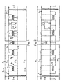
- Figure 1 shows a traction power supply system comprising a catenary C and rails R which constitute a return conductor.
- a positive feeder P and a negative feeder N are provided in parallel with the catenary.
- each of a number of ATs 1 has one end connected to the catenary C and positive feeder P, its mid-point connected to the rails R and its other end connected to the negative feeder N.
- a BT 2 has one winding connected into the positive feeder P and its other winding connected into the negative feeder N. Only one BT 2 is required in each interval between the ATs 1 as there is no leakage to ground from the positive and negative feeders.
- a number of BTs 3a, 3b are provided, each having one winding connected into the catenary C and its other winding connected into the rails R.
- the BT winding may be connected across a single gap in the rails.
- the BT 2 ensures that the positive and negative feeders P, N carry a balanced current I 1 from a feeding station to remote consumers.
- the BTs 3a, 3b ensure that the catenary C and return conductor R carry a balanced local supply current I 2 .
- the catenary C can easily be disconnected from the ATs 1 using disconnecters D, without affecting power transmission to neighbouring sections via the positive and negative feeders P, N.
- FIG. 2 shows an alternative embodiment in which a return conductor R' is provided in parallel with the rails and connected thereto at intervals.
- the BTs balancing the return current with the catenary current are designated by 3.
- Figure 3 shows a third embodiment of the invention in which the positive feeder P is at a higher voltage than the catenary C, each AT 1' being extended and the catenary no longer being connected to the end of the AT winding.
- the frequency is 16.7 Hz.
- the nominal voltage of 50 kV between the positive and negative feeders is the same as in conventional ⁇ 25 kV, 50 or 60 Hz systems, and equipment already made for such systems can be used in the invention. However, the lower frequency gives a very high transmission capability.
- existing BT systems can be adapted in accordance with the invention by providing ATs and positive and negative feeders.
- the distance between the successive ATs will be much greater than in conventional AT systems and thus fewer expensive ATs are required.
Landscapes
- Engineering & Computer Science (AREA)
- Mechanical Engineering (AREA)
- Electric Propulsion And Braking For Vehicles (AREA)
- Control Of Transmission Device (AREA)
- Jib Cranes (AREA)
- Auxiliary Drives, Propulsion Controls, And Safety Devices (AREA)
- Stand-By Power Supply Arrangements (AREA)
- Measurement Of Current Or Voltage (AREA)
- Ignition Installations For Internal Combustion Engines (AREA)
- Emergency Protection Circuit Devices (AREA)
Claims (8)
- Ein Elektrizitätsversorgungssystem für Bahnbetrieb, beinhaltend einen Versorgungsleiter (C), einen Rückleiter (R), einen positiven Speiseleiter (P) und einen negativen Speiseleiter (N), wobei alle vier erwähnten Leiter mit einer Wicklung eines jeden von einer Mehrzahl in Abständen entlang der erwähnten Leiter angeordneten Spartransformatoren verbunden sind, einen Saugtransformator (2), eine Wicklung in den positiven Speiseleiter (P) und eine andere Wicklung in den negativen Speiseleiter (N) verbunden habend und in dem Zwischenraum oder den Zwischenräumen zwischen den Spartransformatoren angeordnet seiend und wenigsten einen weiteren Saugtransformator (3a, 3b), eine Wicklung in den Versorgungsleiter (C) und eine andere Wicklung in den Rückleiter (R) verbunden habend, in dem Zwischenraum oder den Zwischenräumen zwischen den Spartransformatoren (1).
- Ein System nach Anspruch 1, einen Mehrzahl der erwähnten weiteren Saugtransformatoren (3a, 3b) in dem oder jedem Zwischenraum beinhaltend.
- Ein System nach Anspruch 1 oder 2, wobei der positive Speiseleiter (P) and den selben Punkt an der Wicklund des Spartransformators wie der Versorgungsleiter (C) angeschlossen ist.
- Ein System nach Anspruch 1 oder 2, wobei der positive Speiseleiter (P) an einem Punkt der Wicklung des Spartransformators angeschlossen ist, der verschieden ist vom Punkt an der der Versorgungsleiter (C) angeschlossen ist und der positive Speiseleiter eine höhere Spannung hat als der Versorgungsleiter.
- Ein System nach Anspruch 4, wobei der Versorgungsleiter (C) eine Nennspannung von etwa 15 kV hat, positiver und negativer Speiseleiter (P, N) gegen Erde symmetrisch sind und Nennspannungen von etwa +/- 25 kV haben.
- Ein System nach einem der vorgenannten Ansprüche mit einer Frequenz von etwa 16.7 Hz.
- Ein System nach einem der vorgenannten Ansprüche, wobei der Rückleiter (R) aus Schienen besteht, an denen entlang die Fahrzeuge geführt sind.
- Ein System nach einem der vorgenannten Ansprüche, wobei der Rückleiter (R) zu den Schienen, an denen entlang die Fahrzeuge geführt sind, parallel geschaltet ist.
Applications Claiming Priority (3)
| Application Number | Priority Date | Filing Date | Title |
|---|---|---|---|
| GB9910123A GB2349371B (en) | 1999-04-30 | 1999-04-30 | Electricity supply system for traction |
| GB9910123 | 1999-04-30 | ||
| PCT/EP2000/004183 WO2000066389A1 (en) | 1999-04-30 | 2000-04-28 | Electricity supply system for traction |
Publications (2)
| Publication Number | Publication Date |
|---|---|
| EP1175310A1 EP1175310A1 (de) | 2002-01-30 |
| EP1175310B1 true EP1175310B1 (de) | 2002-10-30 |
Family
ID=10852656
Family Applications (1)
| Application Number | Title | Priority Date | Filing Date |
|---|---|---|---|
| EP00931161A Expired - Lifetime EP1175310B1 (de) | 1999-04-30 | 2000-04-28 | Stromversorgungssystem für eisenbahn |
Country Status (7)
| Country | Link |
|---|---|
| EP (1) | EP1175310B1 (de) |
| AT (1) | ATE226900T1 (de) |
| AU (1) | AU4919200A (de) |
| DE (1) | DE60000689T2 (de) |
| GB (1) | GB2349371B (de) |
| NO (1) | NO320193B1 (de) |
| WO (1) | WO2000066389A1 (de) |
Families Citing this family (3)
| Publication number | Priority date | Publication date | Assignee | Title |
|---|---|---|---|---|
| SE0004333L (sv) * | 2000-11-27 | 2002-02-05 | Balfour Beatty Plc | Banmatningssystem |
| FR2978386B1 (fr) * | 2011-07-25 | 2014-09-12 | Egis Rail | Systeme d'alimentation destine a former un circuit electrique d'alimentation d'un vehicule de traction, installation et ensemble ferroviaire comprenant un tel systeme d'alimentation. |
| CN106218447B (zh) * | 2016-08-16 | 2019-01-25 | 深圳市禾望电气股份有限公司 | 一种能馈型牵引供电装置的控制方法和系统 |
Family Cites Families (1)
| Publication number | Priority date | Publication date | Assignee | Title |
|---|---|---|---|---|
| DE301503C (de) * |
-
1999
- 1999-04-30 GB GB9910123A patent/GB2349371B/en not_active Expired - Fee Related
-
2000
- 2000-04-28 DE DE60000689T patent/DE60000689T2/de not_active Expired - Fee Related
- 2000-04-28 AT AT00931161T patent/ATE226900T1/de not_active IP Right Cessation
- 2000-04-28 EP EP00931161A patent/EP1175310B1/de not_active Expired - Lifetime
- 2000-04-28 AU AU49192/00A patent/AU4919200A/en not_active Abandoned
- 2000-04-28 WO PCT/EP2000/004183 patent/WO2000066389A1/en not_active Ceased
-
2001
- 2001-10-29 NO NO20015280A patent/NO320193B1/no unknown
Also Published As
| Publication number | Publication date |
|---|---|
| DE60000689D1 (de) | 2002-12-05 |
| WO2000066389A1 (en) | 2000-11-09 |
| ATE226900T1 (de) | 2002-11-15 |
| AU4919200A (en) | 2000-11-17 |
| GB2349371B (en) | 2002-09-04 |
| NO20015280D0 (no) | 2001-10-29 |
| NO20015280L (no) | 2001-10-29 |
| NO320193B1 (no) | 2005-11-07 |
| GB9910123D0 (en) | 1999-06-30 |
| GB2349371A (en) | 2000-11-01 |
| DE60000689T2 (de) | 2003-04-03 |
| EP1175310A1 (de) | 2002-01-30 |
Similar Documents
| Publication | Publication Date | Title |
|---|---|---|
| WO1988002944A1 (en) | Inductive coupled power system | |
| KR101101498B1 (ko) | 중성점에 근접한 전압탭을 구비한 교류전철용 단권변압기. | |
| EP1181168B1 (de) | Wechselstromversorgungsanlage für eisenbahn | |
| GB2349371A (en) | Electricity supply system for traction | |
| EP1124705B1 (de) | Stromversorgungsanlage für eisenbahn | |
| CN106797182B (zh) | 用于将铁路线路的铁路电源连接到三相供电网的装置 | |
| GB2343431A (en) | AC traction power supply system | |
| US1815842A (en) | Electric transformer and system of distribution | |
| EP1337415A1 (de) | Bahnstromversorgungssystem | |
| EP1356566B1 (de) | System zum transport und zur verteilung von energie auf spannungen zwischen einschliesslich 600 v und 1200 v | |
| US1640539A (en) | Transmission system | |
| US1894338A (en) | Connection for high voltage lines | |
| Sporn et al. | Experience with carrier-current communication on a high-tension interconnected transmission system | |
| SU1300576A1 (ru) | Трансформатор дл железнодорожных нагрузок | |
| US1774645A (en) | Apparatus for reducing interference | |
| US1295887A (en) | System of distribution. | |
| SU1484768A1 (ru) | Устройство тягового электроснабжения железных дорог переменного тока | |
| SU1344640A1 (ru) | Устройство электроснабжени электрических железных дорог переменного тока | |
| US1295933A (en) | Distributing system for electric railways. | |
| KR20260040517A (ko) | 소스 그리드로부터 고객 사이트들에 전력을 제공하기 위한 시스템 및 배전 변압기 | |
| US1638647A (en) | ml taylor | |
| RU1782795C (ru) | Система энергоснабжени электрических железных дорог переменного тока | |
| US1724437A (en) | System of electric transmission | |
| WO2001014165A1 (en) | Traction supply system | |
| Robertson | East Midland Sub-Centre: Chairman's address.“Transmission and distribution of electricity, with special reference to war-time conditions” |
Legal Events
| Date | Code | Title | Description |
|---|---|---|---|
| PUAI | Public reference made under article 153(3) epc to a published international application that has entered the european phase |
Free format text: ORIGINAL CODE: 0009012 |
|
| 17P | Request for examination filed |
Effective date: 20011019 |
|
| AK | Designated contracting states |
Kind code of ref document: A1 Designated state(s): AT BE CH CY DE DK ES FI FR GB GR IE IT LI LU MC NL PT SE |
|
| AX | Request for extension of the european patent |
Free format text: AL;LT;LV;MK;RO;SI |
|
| GRAG | Despatch of communication of intention to grant |
Free format text: ORIGINAL CODE: EPIDOS AGRA |
|
| GRAG | Despatch of communication of intention to grant |
Free format text: ORIGINAL CODE: EPIDOS AGRA |
|
| GRAH | Despatch of communication of intention to grant a patent |
Free format text: ORIGINAL CODE: EPIDOS IGRA |
|
| 17Q | First examination report despatched |
Effective date: 20020503 |
|
| GRAH | Despatch of communication of intention to grant a patent |
Free format text: ORIGINAL CODE: EPIDOS IGRA |
|
| GRAA | (expected) grant |
Free format text: ORIGINAL CODE: 0009210 |
|
| AK | Designated contracting states |
Kind code of ref document: B1 Designated state(s): AT BE CH CY DE DK ES FI FR GB GR IE IT LI LU MC NL PT SE |
|
| PG25 | Lapsed in a contracting state [announced via postgrant information from national office to epo] |
Ref country code: IT Free format text: LAPSE BECAUSE OF FAILURE TO SUBMIT A TRANSLATION OF THE DESCRIPTION OR TO PAY THE FEE WITHIN THE PRESCRIBED TIME-LIMIT;WARNING: LAPSES OF ITALIAN PATENTS WITH EFFECTIVE DATE BEFORE 2007 MAY HAVE OCCURRED AT ANY TIME BEFORE 2007. THE CORRECT EFFECTIVE DATE MAY BE DIFFERENT FROM THE ONE RECORDED. Effective date: 20021030 Ref country code: GR Free format text: LAPSE BECAUSE OF FAILURE TO SUBMIT A TRANSLATION OF THE DESCRIPTION OR TO PAY THE FEE WITHIN THE PRESCRIBED TIME-LIMIT Effective date: 20021030 Ref country code: FR Free format text: LAPSE BECAUSE OF FAILURE TO SUBMIT A TRANSLATION OF THE DESCRIPTION OR TO PAY THE FEE WITHIN THE PRESCRIBED TIME-LIMIT Effective date: 20021030 Ref country code: FI Free format text: LAPSE BECAUSE OF FAILURE TO SUBMIT A TRANSLATION OF THE DESCRIPTION OR TO PAY THE FEE WITHIN THE PRESCRIBED TIME-LIMIT Effective date: 20021030 Ref country code: BE Free format text: LAPSE BECAUSE OF FAILURE TO SUBMIT A TRANSLATION OF THE DESCRIPTION OR TO PAY THE FEE WITHIN THE PRESCRIBED TIME-LIMIT Effective date: 20021030 Ref country code: NL Free format text: LAPSE BECAUSE OF FAILURE TO SUBMIT A TRANSLATION OF THE DESCRIPTION OR TO PAY THE FEE WITHIN THE PRESCRIBED TIME-LIMIT Effective date: 20021030 |
|
| REF | Corresponds to: |
Ref document number: 226900 Country of ref document: AT Date of ref document: 20021115 Kind code of ref document: T |
|
| REG | Reference to a national code |
Ref country code: GB Ref legal event code: FG4D |
|
| RIN1 | Information on inventor provided before grant (corrected) |
Inventor name: SCHUETTE, THORSTEN |
|
| REG | Reference to a national code |
Ref country code: CH Ref legal event code: EP |
|
| REG | Reference to a national code |
Ref country code: IE Ref legal event code: FG4D |
|
| REF | Corresponds to: |
Ref document number: 60000689 Country of ref document: DE Date of ref document: 20021205 |
|
| REG | Reference to a national code |
Ref country code: CH Ref legal event code: NV Representative=s name: RIEDERER HASLER & PARTNER PATENTANWAELTE AG |
|
| PG25 | Lapsed in a contracting state [announced via postgrant information from national office to epo] |
Ref country code: PT Free format text: LAPSE BECAUSE OF FAILURE TO SUBMIT A TRANSLATION OF THE DESCRIPTION OR TO PAY THE FEE WITHIN THE PRESCRIBED TIME-LIMIT Effective date: 20030130 Ref country code: DK Free format text: LAPSE BECAUSE OF FAILURE TO SUBMIT A TRANSLATION OF THE DESCRIPTION OR TO PAY THE FEE WITHIN THE PRESCRIBED TIME-LIMIT Effective date: 20030130 |
|
| NLV1 | Nl: lapsed or annulled due to failure to fulfill the requirements of art. 29p and 29m of the patents act | ||
| LTIE | Lt: invalidation of european patent or patent extension |
Effective date: 20021030 |
|
| PG25 | Lapsed in a contracting state [announced via postgrant information from national office to epo] |
Ref country code: LU Free format text: LAPSE BECAUSE OF NON-PAYMENT OF DUE FEES Effective date: 20030428 Ref country code: IE Free format text: LAPSE BECAUSE OF NON-PAYMENT OF DUE FEES Effective date: 20030428 Ref country code: CY Free format text: LAPSE BECAUSE OF FAILURE TO SUBMIT A TRANSLATION OF THE DESCRIPTION OR TO PAY THE FEE WITHIN THE PRESCRIBED TIME-LIMIT Effective date: 20030428 |
|
| PG25 | Lapsed in a contracting state [announced via postgrant information from national office to epo] |
Ref country code: ES Free format text: LAPSE BECAUSE OF FAILURE TO SUBMIT A TRANSLATION OF THE DESCRIPTION OR TO PAY THE FEE WITHIN THE PRESCRIBED TIME-LIMIT Effective date: 20030429 |
|
| PG25 | Lapsed in a contracting state [announced via postgrant information from national office to epo] |
Ref country code: MC Free format text: LAPSE BECAUSE OF NON-PAYMENT OF DUE FEES Effective date: 20030430 |
|
| EN | Fr: translation not filed | ||
| PLBE | No opposition filed within time limit |
Free format text: ORIGINAL CODE: 0009261 |
|
| STAA | Information on the status of an ep patent application or granted ep patent |
Free format text: STATUS: NO OPPOSITION FILED WITHIN TIME LIMIT |
|
| 26N | No opposition filed |
Effective date: 20030731 |
|
| REG | Reference to a national code |
Ref country code: IE Ref legal event code: MM4A |
|
| PG25 | Lapsed in a contracting state [announced via postgrant information from national office to epo] |
Ref country code: GB Free format text: LAPSE BECAUSE OF NON-PAYMENT OF DUE FEES Effective date: 20040428 |
|
| GBPC | Gb: european patent ceased through non-payment of renewal fee |
Effective date: 20040428 |
|
| PGFP | Annual fee paid to national office [announced via postgrant information from national office to epo] |
Ref country code: CH Payment date: 20080424 Year of fee payment: 9 Ref country code: DE Payment date: 20080421 Year of fee payment: 9 |
|
| PGFP | Annual fee paid to national office [announced via postgrant information from national office to epo] |
Ref country code: AT Payment date: 20080327 Year of fee payment: 9 |
|
| PGFP | Annual fee paid to national office [announced via postgrant information from national office to epo] |
Ref country code: SE Payment date: 20080414 Year of fee payment: 9 |
|
| REG | Reference to a national code |
Ref country code: CH Ref legal event code: PL |
|
| EUG | Se: european patent has lapsed | ||
| PG25 | Lapsed in a contracting state [announced via postgrant information from national office to epo] |
Ref country code: AT Free format text: LAPSE BECAUSE OF NON-PAYMENT OF DUE FEES Effective date: 20090428 Ref country code: DE Free format text: LAPSE BECAUSE OF NON-PAYMENT OF DUE FEES Effective date: 20091103 Ref country code: LI Free format text: LAPSE BECAUSE OF NON-PAYMENT OF DUE FEES Effective date: 20090430 Ref country code: CH Free format text: LAPSE BECAUSE OF NON-PAYMENT OF DUE FEES Effective date: 20090430 |
|
| PG25 | Lapsed in a contracting state [announced via postgrant information from national office to epo] |
Ref country code: SE Free format text: LAPSE BECAUSE OF NON-PAYMENT OF DUE FEES Effective date: 20090429 |