EP1176024B1 - Aufzeichnungsverfahren und Aufzeichnungsgerät - Google Patents
Aufzeichnungsverfahren und Aufzeichnungsgerät Download PDFInfo
- Publication number
- EP1176024B1 EP1176024B1 EP01306327A EP01306327A EP1176024B1 EP 1176024 B1 EP1176024 B1 EP 1176024B1 EP 01306327 A EP01306327 A EP 01306327A EP 01306327 A EP01306327 A EP 01306327A EP 1176024 B1 EP1176024 B1 EP 1176024B1
- Authority
- EP
- European Patent Office
- Prior art keywords
- recording
- dot forming
- secondary scanning
- distance
- dots
- Prior art date
- Legal status (The legal status is an assumption and is not a legal conclusion. Google has not performed a legal analysis and makes no representation as to the accuracy of the status listed.)
- Expired - Lifetime
Links
Images



Classifications
-
- B—PERFORMING OPERATIONS; TRANSPORTING
- B41—PRINTING; LINING MACHINES; TYPEWRITERS; STAMPS
- B41J—TYPEWRITERS; SELECTIVE PRINTING MECHANISMS, i.e. MECHANISMS PRINTING OTHERWISE THAN FROM A FORME; CORRECTION OF TYPOGRAPHICAL ERRORS
- B41J2/00—Typewriters or selective printing mechanisms characterised by the printing or marking process for which they are designed
- B41J2/485—Typewriters or selective printing mechanisms characterised by the printing or marking process for which they are designed characterised by the process of building-up characters or image elements applicable to two or more kinds of printing or marking processes
- B41J2/505—Typewriters or selective printing mechanisms characterised by the printing or marking process for which they are designed characterised by the process of building-up characters or image elements applicable to two or more kinds of printing or marking processes from an assembly of identical printing elements
- B41J2/5056—Typewriters or selective printing mechanisms characterised by the printing or marking process for which they are designed characterised by the process of building-up characters or image elements applicable to two or more kinds of printing or marking processes from an assembly of identical printing elements using dot arrays providing selective dot disposition modes, e.g. different dot densities for high speed and high-quality printing, array line selections for multi-pass printing, or dot shifts for character inclination
-
- B—PERFORMING OPERATIONS; TRANSPORTING
- B41—PRINTING; LINING MACHINES; TYPEWRITERS; STAMPS
- B41J—TYPEWRITERS; SELECTIVE PRINTING MECHANISMS, i.e. MECHANISMS PRINTING OTHERWISE THAN FROM A FORME; CORRECTION OF TYPOGRAPHICAL ERRORS
- B41J19/00—Character- or line-spacing mechanisms
- B41J19/14—Character- or line-spacing mechanisms with means for effecting line or character spacing in either direction
- B41J19/142—Character- or line-spacing mechanisms with means for effecting line or character spacing in either direction with a reciprocating print head printing in both directions across the paper width
-
- B—PERFORMING OPERATIONS; TRANSPORTING
- B41—PRINTING; LINING MACHINES; TYPEWRITERS; STAMPS
- B41J—TYPEWRITERS; SELECTIVE PRINTING MECHANISMS, i.e. MECHANISMS PRINTING OTHERWISE THAN FROM A FORME; CORRECTION OF TYPOGRAPHICAL ERRORS
- B41J2/00—Typewriters or selective printing mechanisms characterised by the printing or marking process for which they are designed
- B41J2/005—Typewriters or selective printing mechanisms characterised by the printing or marking process for which they are designed characterised by bringing liquid or particles selectively into contact with a printing material
- B41J2/01—Ink jet
- B41J2/21—Ink jet for multi-colour printing
- B41J2/2132—Print quality control characterised by dot disposition, e.g. for reducing white stripes or banding
-
- G—PHYSICS
- G06—COMPUTING OR CALCULATING; COUNTING
- G06K—GRAPHICAL DATA READING; PRESENTATION OF DATA; RECORD CARRIERS; HANDLING RECORD CARRIERS
- G06K15/00—Arrangements for producing a permanent visual presentation of the output data, e.g. computer output printers
- G06K15/02—Arrangements for producing a permanent visual presentation of the output data, e.g. computer output printers using printers
- G06K15/10—Arrangements for producing a permanent visual presentation of the output data, e.g. computer output printers using printers by matrix printers
- G06K15/102—Arrangements for producing a permanent visual presentation of the output data, e.g. computer output printers using printers by matrix printers using ink jet print heads
- G06K15/105—Multipass or interlaced printing
Definitions
- the present invention relates to a recording method, and more particularly to the recording method by which while the recording head, having the dot forming element array in which N (N is a positive integer) dot forming elements are aligned at intervals of an even multiple of the distance d between dots in the recording resolution R in the secondary scanning direction which is the direction of conveyance of a recording material, is reciprocally moved in the primary scanning direction perpendicular to the secondary scanning direction, dots are formed on the recording material by the dot forming element array in accordance with recording data, and also the recording material is conveyed in the secondary direction and relatively to the recording head, thus performing recording. Also, the invention relates to a recording apparatus.
- the recording head including a plurality of nozzles (dot forming elements) from which ink droplets are ejected, while being reciprocally moved in a primary scanning direction, ejects ink droplets, and also printing paper (a recording material) is conveyed relatively to the recording head and in the secondary scanning direction perpendicular to the primary scanning direction, whereby printing (recording) is performed.
- the dot diameter formed by ink droplets tends to be smaller than that in case of using dye as ink. Consequently, the width (so-called line width) of the raster formed by aligning a plurality of dots in the primary scanning direction also tends to be narrower.
- each nozzle normally has the deflection (so-called flying curve) peculiar to the nozzle, and ink droplets are not always ejected perpendicularly with respect to the recording head surface on which nozzles are disposed. In this flying curve, there are a flying curve in the secondary scanning direction and a flying curve in the primary scanning direction.
- the gap i.e. the so-called white stripe in which the ground of printing paper remains unprinted
- the space between both rasters becomes wider than an ideal space, so that a white stripe is generated between both rasters.
- the invention is made in light of these circumstances, and its first object is to provide the recording method and the recording apparatus in which by improving the interlacing method, in the bidirectional recording, no striping is generated, and further, recording is possible at a higher speed than in the conventional full-overlap recording method.
- N rasters are formed on the forward trip in the primary scanning direction, whereafter by the second and third steps, the next N rasters adjacent these N respective rasters are formed on the backward trip in the primary scanning direction.
- These N rasters formed on the forward trip and the next N rasters formed on the backward trip are formed by the same dot forming elements. Namely, the recording on the recording material is performed in units of two adjacent rasters formed respectively on the forward and backward trips.
- each raster is formed through the recording on either the forward or backward trip by the same dot forming elements, thus enabling higher-speed printing than in the conventional full-overlap recording method.
- the recording method in the recording method by which, while the recording head, having the dot forming element array in which N (N is a positive integer) dot forming elements are aligned at constant intervals D in the secondary scanning direction which is the direction of conveyance of the recording material, is reciprocally moved in the primary scanning direction perpendicular to the secondary scanning direction, dots are formed on the recording material by the dot forming element array in accordance with recording data, and the recording material is conveyed in the secondary direction and relatively to the recording head, is characterized in that the interval D is the value obtained by multiplying the interval d between dots in the recording resolution in the secondary scanning direction by an even number k , and also the even number k and the dot forming element number N are in prime relation to each other, that there are included a first step of forming dots on the recording material by the dot forming element array while moving the recording head along the forward-trip or backward-trip path in the primary scanning direction, a second step of conveying the recording material in the
- an image is formed in units of two adjacent rasters. Therefore, between two rasters formed by the same dot forming elements, since the dot forming elements for forming these two rasters are the same, the flying curves in the secondary scanning direction are also made the same. Namely, these two rasters, even if any flying curves in the secondary scanning direction are present, are curved in the same direction. Therefore, if the dot diameter is in the order of the theoretical value of dot diameter, a white stripe is never generated between both rasters. Consequently, even in case the invention is used for the ink jet printer using pigment ink, the generation of a white stripe between dots can be prevented between these two rasters.
- the recording method according to a third aspect of the invention in the recording method according to the first or second aspect, is characterized in that two adjacent rasters formed by the same dot forming elements before and after the secondary scanning distance d relative conveyance are made one unit, and another raster adjacent the rasters constituting one unit is formed by the different dot forming elements from the dot forming elements used for forming the unit raster.
- the recording method according to a fourth aspect of the invention in the recording method according to the first or second aspect, is characterized in that the recording head further has M (M is a positive integer not more than N) auxiliary dot forming element arrays aligned at the intervals D in the secondary scanning direction at the upstream-side end portion or downstream-side end portion in the secondary scanning direction of the N dot forming element arrays, and that the auxiliary dot forming element arrays and the M dot forming element arrays at the downstream-side end portion out of the N dot forming element arrays in case the auxiliary dot forming element arrays are disposed at the upstream-side end portion, and the auxiliary dot forming element arrays and the M dot forming element arrays at the upstream-side end portion out of said N dot forming element arrays in case the auxiliary dot forming element arrays are disposed at the downstream-side end portion, form dots intermittently in proper quantities on the same primary scanning line in both the first step and the third step so that dots are not formed
- the dot forming position of M auxiliary dot forming element arrays and the dot forming position of M out of N dot forming elements arrays come to be overlapped.
- Both these dot forming element arrays form dots intermittently in proper quantities so that dots are not formed so as to be superposed on each other at the same position, and there is not produced the place in which not dots are formed at the position where dots are to be formed. Therefore, the partial dots in M rasters are formed before the secondary scanning distance (2N-1) ⁇ d conveyance, and the remaining dots are formed after the conveyance by the same secondary scanning distance.
- the banding generated every time the recording paper is relatively moved in the secondary scanning direction by the conventional interlacing method can be made inconspicuous, and image quality can be improved.
- the recording method according to a fifth aspect of the invention in the recording method according to the fourth aspect, is characterized in that the M auxiliary dot forming element arrays and M out of the N dot forming element arrays form dots intermittently at a ratio of one to one.
- the driving control of the recording head since the ratio of intermittent dot formation is one to one, the driving control of the recording head can be made simple.
- the interval between the rasters formed by the same dot forming elements is set to d+ ⁇ .
- the distance between rasters after the secondary scanning distance (2N-1) ⁇ d movement is made smaller by a.
- the raster formed before secondary scanning distance ⁇ (2N-1) ⁇ d- ⁇ movement and the raster adjacent thereto formed after the secondary scanning distance ⁇ (2N-1) ⁇ d- ⁇ movement are formed by different dot forming elements. Therefore if the actual dot diameter is less than twice the interval d , a white stripe is possibly generated.
- the secondary scanning distance is made smaller by ⁇ , so that even in case the actual dot diameter is less than twice the interval d , the generation of a white stripe between both rasters can be suppressed. Thereby, both between two rasters formed by the same dot forming elements and between two rasters formed by different dot forming elements, the generation of a white stripe is suppressed.
- the second object of the invention is achieved.
- the recording method according to a seventh aspect of the invention in the recording method according to the first or second aspect, is characterized in that the secondary scanning distance in the second step is the distance obtained by adding the offset ⁇ to the distance d , the secondary scanning distance in the fourth step is the distance obtained by subtracting the offset ⁇ from the distance (2N-1) ⁇ d, and the offset ⁇ of a secondary scanning distance is a greater value than zero, and also is the value at which no white stripe is generated either between the adjacent rasters formed before and after secondary scanning distance (d+ ⁇ ) movement or between the rasters formed before and after the secondary scanning distance ⁇ (2N-1) ⁇ d- ⁇ movement.
- the recording method according to the invention of an eighth aspect in the recording method according to the first or second aspect, is characterized in that the recording data for forming dots in the first step and the recording data for forming dots in the third step are the same.
- the recording data in the first and third steps are the same, the recording data can be reduced to one second. Thereby, the time period required for recording data generation processing is also reduced, and the entire recording can be performed at a high speed.
- the recording method according to a ninth aspect of the invention in the recording method according to the sixth aspect, is characterized in that the recording data for forming dots in the first step and the recording data for forming dots in the third step are the same.
- the recording apparatus in the recording apparatus which includes the recording head having the dot forming element array in which N (N is a positive integer) dot forming elements are aligned at constant intervals D in the secondary scanning direction which is the direction of conveyance of the recording material, the head driving means for driving the dot forming elements, the primary scanning driving means for reciprocally moving the recording head in the primary scanning direction perpendicular to the secondary scanning direction with respect to said recording material, the secondary scanning driving means for conveying the recording material in the secondary scanning direction and relatively to the recording head, the control means for controlling the head driving means, the primary scanning driving means, and the secondary scanning driving means, and performs recording while the recording head scans the surface of the recording material in the primary scanning direction and the secondary scanning direction, is characterized in that the interval D is the value obtained by multiplying the interval d between dots in the recording resolution in the secondary scanning direction by an even number k , and also the even number k and the dot forming element number N are in prime relation to each other,
- the recording apparatus in the recording apparatus which includes the recording head having the dot forming element array in which N (N is a positive integer) dot forming elements are aligned at constant intervals D in the secondary scanning direction which is the direction of conveyance of the recording material, the head driving means for driving the dot forming elements, the primary scanning driving means for reciprocally moving the recording head in the primary scanning direction perpendicular to the secondary scanning direction with respect to the recording material, the secondary scanning driving means for conveying the recording material in the secondary scanning direction and relatively to the recording head, the control means for controlling the head driving means, the primary scanning driving means, and the secondary scanning driving means, and performs recording while the recording head scans the surface of the recording material in the primary scanning direction and the secondary scanning direction, is characterized in that the interval D is the value obtained by multiplying the interval d between dots in the recording resolution in the secondary scanning direction by an even number k , and also the even number k and the dot forming element number N are in prime relation to each other, and that
- the recording apparatus in the recording apparatus according to the tenth or eleventh aspect, is characterized by being arranged that two adj acent rasters formed by the same dot forming elements before and after the secondary scanning distance d relative conveyance are made one unit, and another raster adjacent the rasters constituting one unit is formed by the different dot forming elements from the dot forming elements used for forming the unit raster.
- the recording apparatus in the recording apparatus according to the tenth or eleventh aspect, is characterized by being arranged that the recording head further has M (M is a positive integer not more than N) auxiliary dot forming element arrays aligned at the intervals D in the secondary scanning direction at the upstream-side end portion or downstream-side end portion in the secondary scanning direction of the N dot forming element arrays, and that the auxiliary dot forming element arrays and the M dot forming element arrays at the downstream-side end portion out of the N dot forming element arrays in case the auxiliary dot forming element arrays are disposed at the upstream-side end portion, and the auxiliary dot forming element arrays and the M dot forming element arrays at the uptream-side end portion out of the N dot forming element arrays in case the auxiliary dot forming element arrays are disposed at the downstream-side end portion, form dots intermittently in proper quantities on the same primary scanning line by the control means in both the first
- the recording apparatus in the recording apparatus according to the thirteenth aspect, is characterized by being arranged that the M auxiliary dot forming element arrays and M out of the N dot forming element arrays form dots intermittently at a ratio of one to one.
- the recording apparatus in the recording apparatus according to the tenth or eleventh aspect, is characterized in that when the offset ⁇ of a secondary scanning distance is defined as a greater value than zero, and also as a value not more than the value obtained such that the value obtained by multiplying the interval d by a square root of two is subtracted from the dot diameter formed by the dot forming elements, and the value resulting from the subtraction is divided by a square root of two, the control means is arranged such that the secondary scanning distance in the second step is the distance obtained by adding the offset ⁇ to the distance d , and the secondary scanning distance in the fourth step is the distance obtained by subtracting the offset ⁇ from the distance (2N-1) ⁇ d.
- the recording apparatus in the recording apparatus according to the tenth or eleventh aspect, is characterized by being arranged that the secondary scanning distance in the second step is the distance obtained by adding the offset ⁇ to the distance d , the secondary scanning distance in the fourth step is the distance obtained by subtracting the offset ⁇ from the distance (2N-1) ⁇ d, and the offset ⁇ of a secondary scanning distance is a greater value than zero, and also is the value at which no white stripe is generated either between the adjacent rasters formed before and after the secondary scanning distance (d+ ⁇ ) movement or between the rasters formed before and after the secondary scanning distance ⁇ (2N-1) ⁇ d- ⁇ movement.
- the recording apparatus in the recording apparatus according to the tenth or eleventh aspect, is characterized in that the control means is set or can be set such that the recording data for forming dots in the first step and the recording data for forming dots in the third step are the same.
- the recording apparatus in the recording apparatus according to the fifteenth aspect, is characterized in that the control means is set or can be set such that the recording data for forming dots in the first step and the recording data for forming dots in the third step are the same.
- Fig. 1 is a perspective view (partially sectional view) of the color ink jet printer 1 as an example of the "recording apparatus" according to the invention.
- This color ink jet printer (hereinafter referred to simply as a “printer”) 1 includes the recording head 2 for performing printing (recording) on the printing paper S as an example of the "recording material", the primary scanning driving section 3 as the “primary scanning driving means”, and the secondary scanning driving section 4 as the “secondary scanning driving means”.
- nozzles On the surface of the recording head 2 (hereinafter referred to as a "head surface") opposite to the printing paper S, the ink jet nozzles (hereinafter referred to as “nozzles") as an example of the “dot forming elements" are formed.
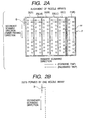
- Fig. 2A is a schematic diagram showing the alignment of the nozzles formed on the head surface of the recording head 2.
- the recording head 2 includes six sets of nozzle arrays 21 to 26 for six color inks.
- the six sets of nozzle arrays 21 to 26 eject black (K), dark cyan (C), light cyan (LC), dark magenta (M), light magenta (LM), and yellow (Y) ink droplets, respctively.
- a plurality of nozzles nz included in each nozzle array are not necessarily staggeringly aligned, and may be linearly aligned.
- the staggering alignment yields an advantage that the nozzle pitch k is easily set to a small value.
- Fig. 2B shows the alignment of a plurality of dots formed by one nozzle array.
- One nozzle array regardless of whether its alignment is staggering or linear, is driven so that the dots to be formed are aligned in substantially a straight line along the secondary scanning direction. Further, as described later, in the plurality of nozzles disposed in each of the nozzle arrays 21 to 26, the entire number thereof is not always used, and only a portion thereof is sometimes used.
- Each nozzle of these nozzle arrays 21 to 26, as shown in Fig. 5, is driven by the head driving section 17 as the "head driving means” under the control of the control unit 15 as the “control means”, and ink droplets are ejected from the nozzles of the recording head 2, thus printing on the printing paper S.
- pigment is used as ink
- the dot diameter (actual dot diameter) a formed by the ink droplets ejected from each nozzle is about 60[ ⁇ m]. Therefore, the dot diameter a is about 1.7 times the interval d between dots (the interval between rasters), and does not reach twice.
- the primary scanning driving section 3 includes the carriage 5 for fixing the recording head 2, a guide rail 6, an endless belt 7, and a carriage motor (e.g. a stepping motor, a DC motor, etc.) 8.
- the rotation and stop of the carriage motor 8 is controlled by the aforesaid control unit 15.
- This control unit 15 rotates the carriage motor 8, whereby the carriage 5 is guided by the guide rail 6 via the endless belt 7, and reciprocally moved in the primary scanning direction.
- the secondary scanning driving section 4 includes a roller pair 9, a roller 10, and a paper feeding motor (e.g. a stepping motor, a DC motor, etc.) 11.
- the rotation and stop of the paper feeding motor 11 is controlled by the aforesaid control unit 15.
- This control unit 15 rotates the paper feeding motor 11, whereby the printing paper S is dragged in by the roller pair 9, and conveyed in the secondary scanning direction via the roller 10.
- control unit 15 controls the primary scanning driving section 3, the secondary scanning driving section 4, and the head driving section 17, and prints on the printing paper S by the recording method to be described later.
- Fig. 3 is a schematic diagram showing the dot formation by the first recording method in the printer 1.
- the #1 to #3 nonuse nozzles are indicated by a white rhombus, and the #4 to #64 use nozzles and the dots formed by these use nozzles are indicated by a white circle or a black circle.
- Fig. 3 shows the dot formation (i.e. raster formation) in six primary scannings of from the n-th scanning after the start of printing to the (n+5)-th primary scanning.
- the n-th, the (n+2)-th, and the (n+4)-th primary scannings are the forward-trip scannings
- the (n+1)-th, the (n+3)-th, and the (n+5)-th primary scannings are the backward-trip scannings.
- the dots formed by the primary scanning on the forward trip are indicated by the white circle
- the dots formed by the primary scanning on the backward trip are indicated by the black circle, respectively.
- each raster is represented as 8 dots.
- the number of dots varies depending on each raster, and more dots than this number or less dots than this number are sometimes formed. Also, dots are formed only at the positions where dots are to be formed, and no dots are formed at any other position. The case is also the same in Fig. 4 to be described later.
- the rasters by the white circle dots are formed by the #4 to #64 nozzles.
- Fig. 3 shows only the raster formation by the #61 to #64 nozzles out thereof.
- Fig. 3 shows it not as the conveyance of the printing paper S, but as the movement of the recording head 2.
- the (n+2)-th forward-trip primary scanning is performed.
- the rasters by the white circle dots are formed by the #4 to #64 nozzles.
- Fig. 3 shows only the raster formation by the #31 to #37 nozzles and the #61 to #64 nozzles out thereof.
- the #31 nozzle forms the raster by the white circle dots at the position adjacent the raster formed by the #61 nozzle, the #32 nozzle at the position adjacent the raster formed by the #62 nozzle, the #33 nozzle at the position adjacent the raster formedby the #63 nozzle, and the #34 nozzle at the position adjacent the raster formed by the #64 nozzle, respectively.
- the black circle dots by the #4 to #64 nozzles are formed by the (n+3)-th backward-trip primary scanning.
- two adjacent rasters formed respectively through the forward and backward trips are formed by the same nozzles.
- each raster is formed through the printing on either the forward or backward trip by the same nozzle, thus enabling higher-speed printing than in the full-overlap recording method.
- the flying curves in the secondary scanning direction are also made the same. Namely, these two rasters, even if any flying curves in the secondary scanning direction are present, are curved in the same direction. Therefore, if the dot diameter a is in the order of the theoretical value of dot diameter (i.e. a square root of two times the interval d between dots in the record resolution in the secondary scanning direction), a white stripe is never generated between rasters.
- Two rasters formed by the same nozzles may be arranged such as to be printed using the same recording data, and may also be arranged such as to be printed using the different recording data corresponding to each raster.
- the recording data amount canbe set to substantially the amount equivalent to 360[DPI], that is, one second of the recording data in the 720 [DPI] printing. Thereby, the recording data amount can be reduced. Also, since the time period required for recording data generation is reduced, high-speed printing also becomes possible.
- Fig. 4 is a schematic diagram showing the dot formation by the second recording method in the printer 1.
- the other #4 to #61 nozzles are used as the nozzles which always form dots at the positions where dots are to be formed.
- the former are called “intermittent nozzles", and the latter "constant-use nozzles”.
- the intermittent nozzles (#62 to #64 nozzles) and the auxiliary nozzles (#1 to #3 nozzles), as described later, are disposed on the same primary scanning line (i.e. the same raster). Both kinds of nozzles are controlled by the control unit and the head driving section so that dots are intermittently formed in proper quantities on the same primary scanning line such that dots are not formed so as to be superposed on each other at the same position, or there is not produced the place in which no dots are formed at the position where dots are to be formed.
- auxiliary nozzles (#1 to #3 nozzles) and the dots formed by these auxiliary nozzles are indicated by a white triangle or a black triangle
- the constant-use nozzles (#4 to #61 nozzles) and the dots formed by these constant-use nozzles by a white circle or a black circle
- the intermittent nozzles (#62 to #64 nozzles) and the dots formed by these intermittent nozzles by a white square or a black square, respectively.
- Fig. 4 shows the dot formation (i.e. raster formation) in six primary scannings of from the n-th scanning after the start of printing to the (n+5)-th primary scanning.
- the n-th, the (n+2)-th, and the (n+4)-th primary scannings are the forward-trip scannings
- the (n+1)-th, the (n+3)-th, and the (n+5)-th primary scannings are the backward-trip scannings.
- the dots formed by the primary scanning on the forward trip are indicated by the white circle, the white square, or the white triangle
- the dots formed by the primary scanning on the backward trip are indicated by the black circle, the black square, or the black triangle, respectively.
- the rasters by the black circle dots are formed by the constant-use nozzles (#4 to #61 nozzles), and also the black square and black triangle dots are formed every two dots by the intermittent nozzles (#62 to #64 nozzles) and the auxiliary nozzles (#1 to #3 nozzles), respectively.
- the intermittent nozzles #62 to #64 nozzles
- the auxiliary nozzles #1 to #3 nozzles
- the (n+2)-th forward-trip primary scanning is performed.
- the rasters by the white circle dots are formed by the constant-use nozzles (#4 to #61 nozzles), and also the white square and white triangle dots are formed every two dots by the intermittent nozzles (#62 to #64 nozzles) and the auxiliary nozzles (#1 to #3 nozzles), respectively.
- the #31 nozzle forms the raster by the white circle dots at the position adjacent the raster formedby the #61 nozzle, the #32 nozzle at the position adjacent the raster formed by the #62 nozzle, the #33 nozzle at the position adjacent the raster formed by the #63 nozzle, and the #34 nozzle at the position adjacent the raster formed by the #64 nozzle, respectively.
- the auxiliary nozzles (#1 to #3 nozzles) and the intermittent nozzles (#62 to #64 nozzles) form dots intermittently.
- the partial dots in six (3 ⁇ 2) rasters are formed before the secondary scanning distance of (2N-1) ⁇ d conveyance, and the remaining dots are formed after the same secondary scanning distance conveyance.
- the conveyance in the secondary scanning direction performed between the n-th primary scanning and the (n+1)-th primary scanning, the conveyance in the secondary scanning direction performed between the (n+2)-th primary scanning and the (n+3)-th primary scanning, and further the conveyance in the secondary scanning direction performed between the (n+4)-th primary scanning and the (n+5)-th primary scanning are all performed by a secondary scanning distance of (d+ ⁇ ).
- the conveyance in the secondary scanning direction performed between the (n+1)-th primary scanning and the (n+2)-th primary scanning, and the conveyance in the secondary scanning direction performed between the (n+3)-th primary scanning and the (n+4)-th primary scanning are both performed by a secondary scanning distance of ⁇ (2N-1) ⁇ d- ⁇ .
- the secondary scanning distance (d+ ⁇ ) conveyance and the secondary scanning distance ⁇ (2N-1) ⁇ d- ⁇ conveyance are alternately repeated.
- the distance between rasters after the secondary scanning distance of (2N-1) ⁇ d movement is made smaller by ⁇ . Since these rasters are formed by different nozzles, if the actual dot diameter d is less than twice the interval d , a white stripe is possibly generated. However, the secondary scanning distance is made smaller by ⁇ , so that the generation of a white stripe can be suppressed also between both rasters.
- the aforesaid first to third recording methods can also be realized by a hardware circuit, and can also be realized as a CUP and the software program executed by the CUP.
- the intermittent nozzles and the auxiliary nozzles both form dots in units of two dots.
- both can also form dots in units of one dot, and further in units of three or more dots.
- the intermittent nozzles and the auxiliary nozzles form dots at a ratio of one to one on the same primary scanning line. Additionally, both can also form dots at a different ratio such as two to one, one to two, three to one, etc.
- the striping generated in every conveyance unit in the secondary scanning direction can be prevented in the entire image. Also, the higher-speed printing than in the conventional full-overlap recording method becomes possible. Further, the generation of a white stripe between dots can be prevented.
Landscapes
- Engineering & Computer Science (AREA)
- Physics & Mathematics (AREA)
- Quality & Reliability (AREA)
- Mathematical Physics (AREA)
- General Engineering & Computer Science (AREA)
- General Physics & Mathematics (AREA)
- Theoretical Computer Science (AREA)
- Ink Jet (AREA)
- Sewing Machines And Sewing (AREA)
- Recording Measured Values (AREA)
- Electronic Switches (AREA)
- Facsimile Scanning Arrangements (AREA)
Claims (32)
- Aufzeichnungsverfahren, in dem, während ein Aufzeichnungskopf, der eine Dot-Bildungs-Element-Anordnung hat, in der N Dot-Bildungs-Elemente in konstanten Intervallen D in einer sekundären Abtastrichtung, die eine Transportrichtung eines Aufzeichnungsmaterials ist, ausgerichtet sind, wechselseitig in eine primäre Abtastrichtung bewegt wird, die senkrecht zur sekundären Abtastrichtung ist, Dots durch die Dot-Bildungs-Element-Anordnur_g gemäß Aufzeichnungsdaten auf dem Aufzeichnungsmaterial gebildet werden, und das Aufzeichnungsmaterial in die sekundäre Richtung und in Bezug auf den Aufzeichnungskopf transportiert wird, wobei N eine positive Ganzzahl ist und das Intervall D ein Wert ist, der durch Multiplizieren eines Intervalls d zwischen Dots in Aufzeichnungsauflösung in der sekundären Abtastrichtung mit einer geraden Zahl k erhalten wird und auch .die gerade Zahl k und die Dot-Bildungs-Element-Anzahl N keinen gemeinsamen Teiler haben, wobei das Aufzeichnungsverfahren die folgenden Schritte umfasst:wobei die ersten bis vierten Schritte wiederholt werden, um dadurch das Aufzeichnen durchzuführen.einen ersten Schritt des Bildens von Dots auf dem Aufzeichnungsmaterial durch die Dot-Bildungs-Element-Anordnung während des Bewegens des Aufzeichnungskopfs entlang eines Vorwärtsbewegungswegs in die primäre Abtastrichtung;einen zweiten Schritt des Transportierens des Aufzeichnungsmaterials in die sekundäre Richtung und in Bezug auf den Aufzeichnungskopf um eine sekundäre Abtastdistanz des Intervalls d zwischen Dots;einen dritten Schritt des Bildens von Dots auf dem Aufzeichnungsmaterial durch die Dot-Bildungs-Element-Anordnung während des Bewegens des Aufzeichnungskopfs entlang eines Rückwärtsbewegungswegs in die primäre Abtastrichtung; undeinen vierten Schritt des Transportierens des Aufzeichnungsmaterials in die sekundäre Abtastrichtung und in Bezug auf den Aufzeichnungskopf um eine sekundäre Abtastdistanz von (2N-1)·d;
- Aufzeichnungsverfahren gemäß Anspruch 1, wobei zwei benachbarte Raster, die durch gleiche Dot-Bildungs-Elemente vor und nach einem relativen Transport um die sekundäre Abtastdistanz d gebildet werden, zu einer Einheit gemacht werden, und ein anderes, den eine Einheit bildenden Rastern benachbartes Raster durch unterschiedliche Dot-Bildungs-Elemente von Dot-Bildungs-Elementen, die zur Bildung des Einheitsrasters verwendet werden, gebildet wird.
- Aufzeichnungsverfahren gemäß Anspruch 1, wobei der Aufzeichnungskopf ferner M zusätzliche Dot-Bildungs-Element-Anordnungen hat, die in den Intervallen D in der sekundären Abtastrichtung an einem Endteil auf der Aufwärtsseite oder einem Endteil auf der Abwärtsseite in der sekundären Abtastrichtung der N Dot-Bildungs-Element-Anordnungen ausgerichtet sind, wobei M eine positive Ganzzahl nicht mehr als N ist und die zusätzlichen Dot-Bildungs-Element-Anordnungen und M Dot-Bildungs-Element-Anordnungen an dem Endteil auf der Abwärtsseite von den N Dot-Bildungs-Element-Anordnungen, wenn die zusätzlichen Dot-Bildungs-Element-Anordnungen an dem Endteil auf der Aufwärtsseite angeordnet sind, und die zusätzlichen Dot-Bildungs-Element-Anordnungen und M Dot-Bildungs-Element-Anordnungen an dem Endteil auf der Aufwärtsseite von den N Dot-Bildungs-Element-Anordnungen, wenn die zusätzlichen Dot-Bildungs-Element-Anordnungen am Endteil auf der Abwärtsseite angeordnet sind, in sowohl dem ersten Schritt als auch dem dritten Schritt mit Unterbrechungen Dots in angemessenen Mengen auf einer gleichen primären Abtastzeile bilden, derart, dass Dots nicht gebildet werden, um sich gegenseitig auf einer gleichen Position zu überlagern, oder keine Stelle hergestellt wird, auf der keine Dots auf einer Position gebildet werden, wo Dots gebildet werden sollen.
- Aufzeichnungsverfahren gemäß Anspruch 3, wobei die M zusätzlichen Dot-Bildungs-Element-Anordnungen und M von den N Dot-Bildungs-Element-Anordnungen mit Unterbrechungen Dots in einem Verhältnis von eins zu eins bilden.
- Aufzeichnungsverfahren gemäß Anspruch 1, wobei, wenn der Versatz α von einer sekundären Abtastdistanz als ein Wert größer als null und auch als ein Wert nicht mehr als ein Wert, der derart erhalten wird, dass ein Wert, der durch Multiplizieren des Intervalls d mit einer Quadratwurzel von zwei erhalten wird, von einem Dot-Durchmesser, der von dem Dot-Bildungs-Element gebildet wird, subtrahiert wird und ein Wert, der sich aus der Subtraktion ergibt, durch eine Quadratwurzel von zwei dividiert wird, definiert ist,
die sekundäre Abtastdistanz im zweiten Schritt eine Distanz ist, die durch Addieren des Versatzes α zur Distanz d erhalten wird, und
die sekundäre Abtastdistanz im vierten Schritt eine Distanz ist, die durch Subtrahieren des Versatzes α von der Distanz (2N-1)·d erhalten wird. - Aufzeichnungsverfahren gemäß Anspruch 1, wobei die sekundäre Abtastdistanz im zweiten Schritt eine Distanz ist, die durch Addieren des Versatzes α zur Distanz d erhalten wird,
die sekundäre Abtastdistanz im vierten Schritt eine Distanz ist, die durch Subtrahieren des Versatzes α von der Distanz (2N-1)·d erhalten wird, und
der Versatz α einer sekundären Abtastdistanz ein Wert größer als null ist und auch ein Wert ist, bei dem kein weißer Streifen entweder zwischen benachbarten Rastern, die vor und nach sekundärer Abtastdistanzbewegung (d + α) oder zwischen Rastern gebildet werden, die vor und nach sekundärer Abtastdistanzbewegung {(2N-1)·d-α} gebildet werden, erzeugt wird. - Aufzeichnungsverfahren gemäß Anspruch 1, wobei die Aufzeichnungsdaten zum Bilden von Dots im ersten Schritt und die Aufzeichnungsdaten zum Bilden von Dots im dritten Schritt gleich sind.
- Aufzeichnungsverfahren gemäß Anspruch 5, wobei die Aufzeichnungsdaten für das Bilden von Dots im ersten Schritt und die Aufzeichnungsdaten zum Bilden von Dots im dritten Schritt gleich sind.
- Aufzeichnungsverfahren, in dem, während ein Aufzeichnungskopf, der eine Dot-Bildungs-Element-Anordnung hat, in der N Dot-Bildungs-Elemente in konstanten Intervallen D in einer sekundären Abtastrichtung, die eine Transportrichtung eines Aufzeichnungsmaterials ist, ausgerichtet sind, wechselseitig in eine primäre Abtastrichtung bewegt wird, die senkrecht zur sekundären Abtastrichtung ist, Dots durch die Dot-Bildungs-Element-Anordnung gemäß Aufzeichnungsdaten auf dem Aufzeichnungsmaterial gebildet werden, und das Aufzeichnungsmaterial in die sekundäre Richtung und in Bezug auf den Aufzeichnungskopf transportiert wird, wobei N eine positive Ganzzahl ist und das Intervall D ein Wert ist, der durch Multiplizieren eines Intervalls d zwischen Dots in Aufzeichnungsauflösung in der sekundären Abtastrichtung mit einer geraden Zahl k erhalten wird und auch die gerade Zahl k und die Dot-Bildungs-Element-Anzahl N keinen gemeinsamen Teiler haben, wobei das Aufzeichnungsverfahren die folgenden Schritte umfasst:wobei die ersten bis vierten Schritte wiederholt werden, um dadurch das Aufzeichnen durchzuführen.einen ersten Schritt des Bildens von Dots auf dem Aufzeichnungsmaterial durch die Dot-Bildungs-Element-Anordnung während des Bewegens des Aufzeichnungskopfs entlang eines Vorwärtsbewegungsoder Rückwärtsbewegungswegs in die primäre Abtastrichtung;einen zweiten Schritt des Transportierens des Aufzeichnungsmaterials in die sekundäre Richtung und in Bezug auf den Aufzeichnungskopf um eine sekundäre Abtastdistanz des Intervalls d zwischen Dots;einen dritten Schritt des Bildens von Dots auf dem Aufzeichnungsmaterial durch die Dot-Bildungs-Element-Anordnung während des Bewegens des Aufzeichnungskopfs entlang eines Vorwärtsbewegungsoder Rückwärtsbewegungswegs in die primäre Abtastrichtung; undeinen vierten Schritt des Transportierens des Aufzeichnungsmaterials in die sekundäre Abtastrichtung und in Bezug auf den Aufzeichnungskopf um eine sekundäre Abtastdistanz von (2N-1)·d;
- Aufzeichnungsverfahren gemäß Anspruch 9, wobei zwei benachbarte Raster, die durch gleiche Dot-Bildungs-Elemente vor und nach einem relativen Transport um die sekundäre Abtastdistanz d gebildet werden, zu einer Einheit gemacht werden, und ein anderes, den eine Einheit bildenden Rastern benachbartes Raster durch unterschiedliche Dot-Bildungs-Elemente von Dot-Bildungs-Elementen, die zur Bildung des Einheitsrasters verwendet werden, gebildet wird.
- Aufzeichnungsverfahren gemäß Anspruch 9, wobei der Aufzeichnungskopf ferner M zusätzliche Dot-Bildungs-Element-Anordnungen hat, die in den Intervallen D in der sekundären Abtastrichtung an einem Endteil auf der Aufwärtsseite oder einem Endteil auf der Abwärtsseite in der sekundären Abtastrichtung der N Dot-Bildungs-Element-Anordnungen ausgerichtet sind, wobei M eine positive Ganzzahl nicht mehr als N ist und die zusätzlichen Dot-Bildungs-Element-Anordnungen und M Dot-Bildungs-Element-Anordnungen an dem Endteil auf der Abwärtsseite von den N Dot-Bildungs-Element-Anordnungen, wenn die zusätzlichen Dot-Bildungs-Element-Anordnungen an dem Endteil auf der Aufwärtsseite angeordnet sind, und die zusätzlichen Dot-Bildungs-Element-Anordnungen und M Dot-Bildungs-Element-Anordnungen an dem Endteil auf der Aufwärtsseite von den N Dot-Bildungs-Element-Anordnungen, wenn die zusätzlichen Dot-Bildungs-Element-Anordnungen am Endteil auf der Abwärtsseite angeordnet sind, in sowohl dem ersten Schritt als auch dem dritten Schritt mit Unterbrechungen Dots in angemessenen Mengen auf einer gleichen primären Abtastzeile bilden, derart, dass Dots nicht gebildet werden, um sich gegenseitig auf einer gleichen Position zu überlagern, oder keine Stelle hergestellt wird, auf der keine Dots auf einer Position gebildet werden, wo Dots gebildet werden sollen.
- Aufzeichnungsverfahren gemäß Anspruch 11, wobei die M zusätzlichen Dot-Bildungs-Element-Anordnungen und M von den N Dot-Bildungs-Element-Anordnungen mit Unterbrechungen Dots in einem Verhältnis von eins zu eins bilden.
- Aufzeichnungsverfahren gemäß Anspruch 9, wobei, wenn der Versatz α von einer sekundären Abtastdistanz als ein Wert größer als null und auch als ein Wert nicht mehr als ein Wert, der derart erhalten wird, dass ein Wert, der durch Multiplizieren des Intervalls d mit einer Quadratwurzel von zwei erhalten wird, von einem Dot-Durchmesser, der von dem Dot-Bildungs-Element gebildet wird, subtrahiert wird und ein Wert, der sich aus der Subtraktion ergibt, durch eine Quadratwurzel von zwei dividiert wird, definiert ist,
die sekundäre Abtastdistanz im zweiten Schritt eine Distanz ist, die durch Addieren des Versatzes α zur Distanz d erhalten wird, und
die sekundäre Abtastdistanz im vierten Schritt eine Distanz ist, die durch Subtrahieren des Versatzes α von der Distanz (2N-1)·d erhalten wird. - Aufzeichnungsverfahren gemäß Anspruch 9, wobei die sekundäre Abtastdistanz im zweiten Schritt eine Distanz ist, die durch Addieren des Versatzes α zur Distanz d erhalten wird,
die sekundäre Abtastdistanz im vierten Schritt eine Distanz ist, die durch Subtrahieren des Versatzes α von der Distanz (2N-1)·d erhalten wird, und
der Versatz α einer sekundären Abtastdistanz ein Wert größer als null ist und auch ein Wert ist, bei dem kein weißer Streifen entweder zwischen benachbarten Rastern, die vor und nach sekundärer Abtastdistanzbewegung (d + α) oder zwischen Rastern gebildet werden, die vor und nach sekundärer Abtastdistanzbewegung {(2N-1)·d-α} gebildet werden, erzeugt wird. - Aufzeichnungsverfahren gemäß Anspruch 9, wobei die Aufzeichnungsdaten zum Bilden von Dots im ersten Schritt und die Aufzeichnungsdaten zum Bilden von Dots im dritten Schritt gleich sind.
- Aufzeichnungsverfahren gemäß Anspruch 13, wobei die Aufzeichnungsdaten für das Bilden von Dots im ersten Schritt und die Aufzeichnungsdaten zum Bilden von Dots im dritten Schritt gleich sind.
- Aufzeichnungsvorrichtung, die Folgendes umfasst:wobei das Intervall D ein Wert ist, der durch Multiplizieren eines Intervalls d zwischen Dots in Aufzeichnungsauflösung in der sekundären Abtastrichtung mit einer geraden Zahl k erhalten wird und auch die gerade Zahl k und die Dot-Bildungs-Element-Anzahl N keinen gemeinsamen Teiler haben, und das Aufzeichnen durch solche Wiederholung durchgeführt wird; undeinen Aufzeichnungskopf, der eine Dot-Bildungs-Element-Anordnung hat, in der N (N ist eine positive Ganzzahl) Dot-Bildungs-Elemente in konstanten Intervallen D in einer sekundären Abtastrichtung, die eine Transportrichtung eines Aufzeichnungsmaterials ist, ausgerichtet sind;ein Kopfantriebsmittel zum Antreiben der Dot-Bildungs-Elemente;ein primäres Abtastantriebsmittel zum wechselseitigen Bewegen des Aufzeichnungskopfs in eine primäre Abtastrichtung, die senkrecht zur sekundären Abtastrichtung ist, in Bezug auf das Aufzeichnungsmaterial;ein sekundäres Abtastantriebsmittel zum Transportieren des Aufzeichnungsmaterials in die sekundäre Abtastrichtung und in Bezug auf den Aufzeichnungskopf; undein Steuermittel zum Steuern des Kopfantriebsmittels, des primären Abtastantriebsmitiels und des sekundären Abtastantriebsmittels, um dadurch das Aufzeichnen durchzuführen, während der Aufzeichnungskopf eine Fläche des Aufzeichnungsmaterials in der primären Abtastrichtung und der sekundären Abtastrichtung abtastet;
wobei das Steuermittel des Weiteren das primäre Abtastantriebsmittel und das Kopfantriebsmittel steuert, um durch die Dot-Bildungs-Element-Anordnung Dots auf dem Aufzeichnungsmaterial zu bilden, während der Aufzeichnungskopf entlang eines Vorwärtsbewegungswegs in die primäre Abtastrichtung bewegt wird,
das sekundäre Abtastantriebsmittel steuert, um das Aufzeichnungsmaterial in die sekundäre Richtung und in Bezug auf den Aufzeichnungskopf um eine sekundäre Abtastdistanz von dem Intervall d zwischen Dots zu bewegen,
das primäre Abtastantriebsmittel und das Kopfantriebsmittel steuert, um durch die Dot-Bildungs-Element-Anordnung Dots auf dem Aufzeichnungsmaterial zu bilden, während der Aufzeichnungskopf entlang eines Rückwärtsbewegungswegs in die primäre Abtastrichtung bewegt wird, und
das sekundäre Abtastantriebsmittel steuert, um das Aufzeichnungsmaterial in die sekundäre Abtastrichtung und in Bezug auf den Aufzeichnungskopf um eine sekundäre Abtastdistanz von (2N-1)·d zu transportieren. - Aufzeichnungsvorrichtung gemäß Anspruch 17, wobei zwei benachbarte Raster, die durch gleiche Dot-Bildungs-Elemente vor und nach einem relativen Transport um die sekundäre Abtastdistanz d gebildet werden, zu einer Einheit gemacht werden, und ein anderes, den eine Einheit bildenden Rastern benachbartes Raster durch unterschiedliche Dot-Bildungs-Elemente von Dot-Bildungs-Elementen, die zur Bildung des Einheitsrasters verwendet werden, gebildet wird.
- Aufzeichnungsvorrichtung gemäß Anspruch 17, wobei der Aufzeichnungskopf ferner M (M ist eine positive Ganzzahl nicht mehr als N) zusätzliche Dot-Bildungs-Element-Anordnungen hat, die in den Intervallen D in der sekundären Abtastrichtung an einem Endteil auf der Aufwärtsseite oder einem Endteil auf der Abwärtsseite in der sekundären Abtastrichtung der N Dot-Bildungs-Element-Anordnungen ausgerichtet sind, und
die zusätzlichen Dot-Bildungs-Element-Anordnungen und M Dot-Bildungs-Element-Anordnungen an dem Endteil auf der Abwärtsseite von den N Dot-Bildungs-Element-Anordnungen, wenn die zusätzlichen Dot-Bildungs-Element-Anordnungen an dem Endteil auf der Aufwärtsseite angeordnet sind, und die zusätzlichen Dot-Bildungs-Element-Anordnungen und M Dot-Bildungs-Element-Anordnungen an dem Endteil auf der Aufwärtsseite von den N Dot-Bildungs-Element-Anordnungen, wenn die zusätzlichen Dot-Bildungs-Element-Anordnungen an dem Endteil auf der Abwärtsseite angeordnet sind, mit Unterbrechungen Dots in angemessenen Mengen auf einer gleichen primären Abtastzeile durch die Steuermittel in sowohl dem ersten Schritt als auch dem dritten Schritt bilden, derart, dass Dots nicht gebildet werden, um sich gegenseitig auf gleichen Positionen zu überlagern, oder keine Stelle hergestellt wird, auf der keine Dots auf einer Position gebildet werden, wo Dots gebildet werden sollen. - Aufzeichnungsvorrichtung gemäß Anspruch 19, wobei die M zusätzlichen Dot-Bildungs-Element-Anordnungen und M von den N Dot-Bildungs-Element-Anordnungen mit Unterbrechungen Dots in einem Verhältnis von eins zu eins bilden.
- Aufzeichnungsvorrichtung gemäß Anspruch 17, wobei, wenn der Versatz α von einer sekundären Abtastdistanz als ein Wert größer als null und auch als ein Wert nicht mehr als ein Wert, der derart erhalten wird, dass ein Wert, der durch Multiplizieren des Intervalls d mit einer Quadratwurzel von zwei erhalten wird, von einem Dot-Durchmesser, der von den Dot-Bildungs-Elementen gebildet wird, subtrahiert wird und ein Wert, der sich aus der Subtraktion ergibt, durch eine Quadratwurzel von zwei dividiert wird, definiert ist, das Steuermittel derart angeordnet ist, dass
die sekundäre Abtastdistanz im zweiten Schritt eine Distanz ist, die durch Addieren des Versatzes α zur Distanz d erhalten wird, und
die sekundäre Abtastdistanz im vierten Schritt eine Distanz ist, die durch Subtrahieren des Versatzes α von der Distanz (2N-1)·d erhalten wird. - Aufzeichnungsvorrichtung gemäß Anspruch 17, wobei die sekundäre Abtastdistanz im zweiten Schritt eine Distanz ist, die durch Addieren des Versatzes α zur Distanz d erhalten wird,
die sekundäre Abtastdistanz im vierten Schritt eine Distanz ist, die durch Subtrahieren des Versatzes α von der Distanz (2N-1)·d erhalten wird, und
der Versatz α einer sekundären Abtastdistanz ein Wert größer als null ist und auch ein Wert ist, bei dem kein weißer Streifen entweder zwischen benachbarten Rastern, die vor und nach sekundärer Abtastdistanzbewegung (d + α) oder zwischen Rastern gebildet werden, die vor und nach sekundärer Abtastdistanzbewegung {(2N-1)·d-α} gebildet werden, erzeugt wird. - Aufzeichnungsvorrichtung gemäß Anspruch 17, wobei das Steuermittel derart eingestellt ist oder eingestellt werden kann, dass die Aufzeichnungsdaten zum Bilden von Dots im ersten Schritt und die Aufzeichnungsdaten zum Bilden von Dots im dritten Schritt gleich sind.
- Aufzeichnungsvorrichtung gemäß Anspruch 21, wobei das Steuermittel derart eingestellt ist oder eingestellt werden kann, dass die Aufzeichnungsdaten zum Bilden von Dots im ersten Schritt und die Aufzeichnungsdaten zum Bilden von Dots im dritten Schritt gleich sind.
- Aufzeichnungsvorrichtung, die Folgendes umfasst:wobei das Intervall D ein Wert ist, der durch Multiplizieren eines Intervalls d zwischen Dots in Aufzeichnungsauflösung in der sekundären Abtastrichtung mit einer geraden Zahl k erhalten wird und auch die gerade Zahl k und die Dot-Bildungs-Element-Anzahl N keinen gemeinsamen Teiler haben, und das Aufzeichnen durch solche Wiederholung durchgeführt wird; undeinen Aufzeichnungskopf, der eine Dot-Bildungs-Element-Anordnung hat, in der N (N ist eine positive Ganzzahl) Dot-Bildungs-Elemente in konstanten Intervallen D in einer sekundären Abtastrichtung, die eine Transportrichtung eines Aufzeichnungsmaterials ist, ausgerichtet sind;ein Kopfantriebsmittel zum Antreiben der Dot-Bildungs-Elemente;ein primäres Abtastantriebsmittel zum wechselseitigen Bewegen des Aufzeichnungskopfs in eine primäre Abtastrichtung, die senkrecht zur sekundären Abtastrichtung ist, in Bezug auf das Aufzeichnungsmaterial;ein sekundäres Abtastantriebsmittel zum Transportieren des Aufzeichnungsmaterials in die sekundäre Abtastrichtung und in Bezug auf den Aufzeichnungskopf;ein Steuermittel zum Steuern des Kopfantriebsmittels, des primären Abtastantriebsmittels und des sekundären Abtastantriebsmittels, um dadurch das Aufzeichnen durchzuführen, während der Aufzeichnungskopf eine Fläche des Aufzeichnungsmaterials in der primären Abtastrichtung und der sekundären Abtastrichtung abtastet;
wobei das Steuermittel ferner das primäre Abtastantriebsmittel und das Kopfantriebsmittel steuert, um durch die Dot-Bildungs-Element-Anordnung Dots auf dem Aufzeichnungsmaterial zu bilden, während der Rufzeichnungskopf entlang eines Vorwärtsbewegungs- oder Rückwärtsbewegungswegs in die primäre Abtastrichtung bewegt wird,
das sekundäre Abtastantriebsmittel steuert, um das Auf zeichnungsmaterial in die sekundäre Richtung und in Bezug auf den Aufzeichnungskopf um eine sekundäre Abtastdistanz von dem Intervall d zwischen Dots zu bewegen,
das primäre Abtastantriebsmittel und das Kopfantriebsmittel steuert, um durch die Dot-Bildungs-Element-Anordnung Dots auf dem Aufzeichnungsmaterial zu bilden, während der Aufzeichnungskopf entlang eines Vorwärtsbewegungs- oder Rückwärtsbewegungswegs in die primäre Abtastrichtung bewegt wird, und
das sekundäre Abtastantriebsmittel steuert, um das Aufzeichnungsmaterial in die sekundäre Abtastrichtung und in Bezug auf den Aufzeichnungskopf um eine sekundäre Abtastdistanz von (2N-1)·d zu transportieren. - Aufzeichnungsvorrichtung gemäß Anspruch 25, wobei zwei benachbarte Raster, die durch gleiche Dot-Bildungs-Elemente vor und nach einem relativen Transport um die sekundäre Abtastdistanz d gebildet werden, zu einer Einheit gemacht werden, und ein anderes, den eine Einheit bildenden Rastern benachbartes Raster durch unterschiedliche Dot-Bildungs-Elemente von Dot-Bildungs-Elementen, die zur Bildung des Einheitsrasters verwendet werden, gebildet wird.
- Aufzeichnungsvorrichtung gemäß Anspruch 25, wobei der Aufzeichnungskopf ferner M (M ist eine positive Ganzzahl nicht mehr als N) zusätzliche Dot-Bildungs-Element-Anordnungen hat, die in den Intervallen D in der sekundären Abtastrichtung an einem Endteil auf der Aufwärtsseite oder einem Endteil auf der Abwärtsseite in der sekundären Abtastrichtung der N Dot-Bildungs-Element-Anordnungen ausgerichtet sind, und
die zusätzlichen Dot-Bildungs-Element-Anordnungen und M Dot-Bildungs-Element-Anordnungen an dem Endteil auf der Abwärtsseite von den N Dot-Bildungs-Element-Anordnungen, wenn die zusätzlichen Dot-Bildungs-Element-Anordnungen an dem Endteil auf der Aufwärtsseite angeordnet sind, und die zusätzlichen Dot-Bildungs-Element-Anordnungen und M Dot-Bildungs-Element-Anordnungen an dem Endteil auf der Aufwärtsseite von den N Dot-Bildungs-Element-Anordnungen, wenn die zusätzlichen Dot-Bildungs-Element-Anordnungen an dem Endteil auf der Abwärtsseite angeordnet sind, mit Unterbrechungen Dots in angemessenen Mengen auf einer gleichen primären Abtastzeile durch die Steuermittel in sowohl dem ersten Schritt als auch dem dritten Schritt bilden, derart, dass Dots nicht gebildet werden, um sich gegenseitig auf gleichen Positionen zu überlagern, oder keine Stelle hergestellt wird, auf der keine Dots auf einer Position gebildet werden, wo Dots gebildet werden sollen. - Aufzeichnungsvorrichtung gemäß Anspruch 27, wobei die M zusätzlichen Dot-Bildungs-Element-Anordnungen und M von den N Dot-Bildungs-Element-Anordnungen mit Unterbrechungen Dots in einem Verhältnis von eins zu eins bilden.
- Aufzeichnungsvorrichtung gemäß Anspruch 25, wobei, wenn der Versatz α von einer sekundären Abtastdistanz als ein Wert größer als null und auch als ein Wert nicht mehr als ein Wert, der derart erhalten wird, dass ein Wert, der durch Multiplizieren des Intervalls d mit einer Quadratwurzel von zwei erhalten wird, von einem Dot-Durchmesser, der von den Dot-Bildungs-Elementen gebildet wird, subtrahiert wird und ein Wert, der sich aus der Subtraktion ergibt, durch eine Quadratwurzel von zwei dividiert wird, definiert ist, das Steuermittel derart angeordnet ist, dass
die sekundäre Abtastdistanz im zweiten Schritt eine Distanz ist, die durch Addieren des Versatzes α zur Distanz d erhalten wird, und
die sekundäre Abtastdistanz im vierten Schritt eine Distanz ist, die durch Subtrahieren des Versatzes α von der Distanz (2N-1)·d erhalten wird. - Aufzeichnungsvorrichtung gemäß Anspruch 25, wobei die sekundäre Abtastdistanz im zweiten Schritt eine Distanz ist, erhalten wird die durch Addieren des Versatzes α zur Distanz d,
die sekundäre Abtastdistanz im vierten Schritt eine Distanz ist, die durch Subtrahieren des Versatzes α von der Distanz (2N-1)·d erhalten wird, und
der Versatz α einer sekundären Abtastdistanz ein Wert größer als null ist und auch ein Wert ist, bei dem kein weißer Streifen entweder zwischen benachbarten Rastern, die vor und nach sekundärer. Abtastdistanzbewegung (d +α) oder zwischen Rastern, gebildet werden, die vor und nach sekundärer Abtastdistanzbewegung {(2N-1)·d-α} gebildet werden, erzeugt wird. - Aufzeichnungsvorrichtung gemäß Anspruch 25, wobei das Steuermittel derart eingestellt ist oder eingestellt werden kann, dass die Aufzeichnungsdaten zum Bilden von Dots im ersten Schritt und die Aufzeichnungsdaten zum Bilden von Dots im dritten Schritt gleich sind.
- Aufzeichnungsvorrichtung gemäß Anspruch 29, wobei das Steuermittel derart eingestellt ist oder eingestellt werden kann, dass die Aufzeichnungsdaten zum Bilden von Dots im ersten Schritt und die Aufzeichnungsdaten zum Bilden von Dots im dritten Schritt gleich sind.
Applications Claiming Priority (4)
| Application Number | Priority Date | Filing Date | Title |
|---|---|---|---|
| JP2000221965 | 2000-07-24 | ||
| JP2000221965 | 2000-07-24 | ||
| JP2001210857A JP4277164B2 (ja) | 2000-07-24 | 2001-07-11 | 記録方法および記録装置 |
| JP2001210857 | 2001-07-11 |
Publications (2)
| Publication Number | Publication Date |
|---|---|
| EP1176024A1 EP1176024A1 (de) | 2002-01-30 |
| EP1176024B1 true EP1176024B1 (de) | 2005-11-16 |
Family
ID=26596520
Family Applications (1)
| Application Number | Title | Priority Date | Filing Date |
|---|---|---|---|
| EP01306327A Expired - Lifetime EP1176024B1 (de) | 2000-07-24 | 2001-07-24 | Aufzeichnungsverfahren und Aufzeichnungsgerät |
Country Status (5)
| Country | Link |
|---|---|
| US (1) | US6485125B2 (de) |
| EP (1) | EP1176024B1 (de) |
| JP (1) | JP4277164B2 (de) |
| AT (1) | ATE309913T1 (de) |
| DE (1) | DE60114944T8 (de) |
Families Citing this family (7)
| Publication number | Priority date | Publication date | Assignee | Title |
|---|---|---|---|---|
| US7290855B2 (en) * | 2004-08-18 | 2007-11-06 | Canon Kabushiki Kaisha | Printing apparatus and printing method |
| JP5288747B2 (ja) * | 2007-08-20 | 2013-09-11 | キヤノン株式会社 | インクジェット記録装置およびインクジェット記録方法 |
| US8128187B2 (en) | 2008-03-31 | 2012-03-06 | Fujifilm Corporation | Recording head, droplet discharge device and droplet discharge method |
| WO2010065697A1 (en) * | 2008-12-03 | 2010-06-10 | Videojet Technologies Inc. | An inkjet printing system and method |
| US8300269B2 (en) * | 2009-03-30 | 2012-10-30 | Eastman Kodak Company | Dot forming element arrays at different resolutions |
| JP6798372B2 (ja) * | 2017-03-14 | 2020-12-09 | オムロン株式会社 | 導光体、表示装置及び遊技機 |
| JP6991845B2 (ja) * | 2017-12-05 | 2022-01-13 | キヤノン株式会社 | 記録装置、記録方法、およびプログラム |
Family Cites Families (7)
| Publication number | Priority date | Publication date | Assignee | Title |
|---|---|---|---|---|
| US4063254A (en) | 1976-06-28 | 1977-12-13 | International Business Machines Corporation | Multiple array printer |
| US4198642A (en) | 1978-01-09 | 1980-04-15 | The Mead Corporation | Ink jet printer having interlaced print scheme |
| EP0428658A4 (en) | 1989-05-31 | 1992-04-22 | Spectra, Inc. | Reduced banding in bidirectional ink jet printing |
| US5686944A (en) * | 1994-03-02 | 1997-11-11 | Seiko Epson Corporation | Serial printer with hybrid print control of interlaced and minute feed printing |
| US6250739B1 (en) * | 1997-03-04 | 2001-06-26 | Hewlett-Packard Company | Bidirectional color printmodes with semistaggered swaths to minimize hue shift and other artifacts |
| JP4193216B2 (ja) * | 1997-04-08 | 2008-12-10 | セイコーエプソン株式会社 | ドット記録方法およびドット記録装置 |
| US6241338B1 (en) * | 1998-08-06 | 2001-06-05 | Seiko Epson Corporation | Dot printing using partial overlap scheme |
-
2001
- 2001-07-11 JP JP2001210857A patent/JP4277164B2/ja not_active Expired - Fee Related
- 2001-07-24 US US09/910,755 patent/US6485125B2/en not_active Expired - Lifetime
- 2001-07-24 AT AT01306327T patent/ATE309913T1/de not_active IP Right Cessation
- 2001-07-24 DE DE60114944T patent/DE60114944T8/de active Active
- 2001-07-24 EP EP01306327A patent/EP1176024B1/de not_active Expired - Lifetime
Also Published As
| Publication number | Publication date |
|---|---|
| EP1176024A1 (de) | 2002-01-30 |
| US6485125B2 (en) | 2002-11-26 |
| JP2002103579A (ja) | 2002-04-09 |
| ATE309913T1 (de) | 2005-12-15 |
| DE60114944T8 (de) | 2006-11-16 |
| DE60114944T2 (de) | 2006-07-27 |
| DE60114944D1 (de) | 2005-12-22 |
| JP4277164B2 (ja) | 2009-06-10 |
| US20020024555A1 (en) | 2002-02-28 |
Similar Documents
| Publication | Publication Date | Title |
|---|---|---|
| US6848765B1 (en) | End-of-page advance-distance decrease, in liquid-ink printers | |
| US8091977B2 (en) | Inkjet printing apparatus and inkjet printing method | |
| EP0861730B1 (de) | Verfahren zur Herstellung eines Druckkopfes zur Verwendung in einem Tintenstrahldrucker und Druckverfahren unter Verwendung desselben | |
| EP1407886B1 (de) | Verfahren für Mehrfarbentintenstrahldrucken und Druckgerät | |
| WO1990002925A1 (en) | Dual mode ink jet printer | |
| EP0933218A3 (de) | Hybrides Drucksystem unter Verwendung von Mehrfachströpfen und Mehrfach-Durchlauf | |
| EP0817114B1 (de) | Punktzuweisungsplanung in Tintenstrahldruckern | |
| EP1176024B1 (de) | Aufzeichnungsverfahren und Aufzeichnungsgerät | |
| EP0730247B1 (de) | Tintenstrahldruckverfahren unter Verwendung von Farbenverstärkung in schwarzen Gebieten | |
| JPH10157172A (ja) | インクジェットプリントにおいて高解像度のx/y軸アドレス指定能力を達成するための過大インク滴に関するエッジ強調削減技法 | |
| JP2000118013A (ja) | インクジェットプリンタ用マルチパス色ずれ補正方法 | |
| US6425699B1 (en) | Use of very small advances of printing medium for improved image quality in incremental printing | |
| US6336706B1 (en) | Color printing using a vertical nozzle array head | |
| JP4277165B2 (ja) | 記録装置 | |
| US6357856B1 (en) | Printing with a vertical nozzle array head | |
| JP4539182B2 (ja) | 印刷装置、コンピュータプログラム、印刷システム、及び、印刷方法 | |
| US20120194614A1 (en) | Inkjet printing apparatus and inkjet printing method | |
| JP3485065B2 (ja) | 複数の送り量を組み合わせた副走査を行う印刷処理 | |
| JP4194226B2 (ja) | インクジェット記録装置および画像データ補正方法 | |
| JP3775143B2 (ja) | 縦配列ヘッドを用いたカラー印刷装置及び印刷方法、並びに、記録媒体 | |
| JP4666759B2 (ja) | インクジェット記録装置及びインクジェット記録方法 | |
| EP1219450B1 (de) | Druckvorrichtung und -verfahren | |
| JP4604570B2 (ja) | 調整用パターンの形成方法、調整用パターン、印刷方法、及び、印刷装置 | |
| EP1216838B1 (de) | Tintenstrahldrucker mit relativ zueinander beweglichen Düsenreihen | |
| JP3674121B2 (ja) | プリンタ装置、プリンタヘッドおよび画像形成方法 |
Legal Events
| Date | Code | Title | Description |
|---|---|---|---|
| PUAI | Public reference made under article 153(3) epc to a published international application that has entered the european phase |
Free format text: ORIGINAL CODE: 0009012 |
|
| AK | Designated contracting states |
Kind code of ref document: A1 Designated state(s): AT BE CH CY DE DK ES FI FR GB GR IE IT LI LU MC NL PT SE TR |
|
| AX | Request for extension of the european patent |
Free format text: AL;LT;LV;MK;RO;SI |
|
| 17P | Request for examination filed |
Effective date: 20020624 |
|
| AKX | Designation fees paid |
Free format text: AT BE CH CY DE DK ES FI FR GB GR IE IT LI LU MC NL PT SE TR |
|
| GRAP | Despatch of communication of intention to grant a patent |
Free format text: ORIGINAL CODE: EPIDOSNIGR1 |
|
| GRAS | Grant fee paid |
Free format text: ORIGINAL CODE: EPIDOSNIGR3 |
|
| GRAA | (expected) grant |
Free format text: ORIGINAL CODE: 0009210 |
|
| AK | Designated contracting states |
Kind code of ref document: B1 Designated state(s): AT BE CH CY DE DK ES FI FR GB GR IE IT LI LU MC NL PT SE TR |
|
| PG25 | Lapsed in a contracting state [announced via postgrant information from national office to epo] |
Ref country code: IT Free format text: LAPSE BECAUSE OF FAILURE TO SUBMIT A TRANSLATION OF THE DESCRIPTION OR TO PAY THE FEE WITHIN THE PRESCRIBED TIME-LIMIT;WARNING: LAPSES OF ITALIAN PATENTS WITH EFFECTIVE DATE BEFORE 2007 MAY HAVE OCCURRED AT ANY TIME BEFORE 2007. THE CORRECT EFFECTIVE DATE MAY BE DIFFERENT FROM THE ONE RECORDED. Effective date: 20051116 Ref country code: NL Free format text: LAPSE BECAUSE OF FAILURE TO SUBMIT A TRANSLATION OF THE DESCRIPTION OR TO PAY THE FEE WITHIN THE PRESCRIBED TIME-LIMIT Effective date: 20051116 Ref country code: LI Free format text: LAPSE BECAUSE OF FAILURE TO SUBMIT A TRANSLATION OF THE DESCRIPTION OR TO PAY THE FEE WITHIN THE PRESCRIBED TIME-LIMIT Effective date: 20051116 Ref country code: FI Free format text: LAPSE BECAUSE OF FAILURE TO SUBMIT A TRANSLATION OF THE DESCRIPTION OR TO PAY THE FEE WITHIN THE PRESCRIBED TIME-LIMIT Effective date: 20051116 Ref country code: AT Free format text: LAPSE BECAUSE OF FAILURE TO SUBMIT A TRANSLATION OF THE DESCRIPTION OR TO PAY THE FEE WITHIN THE PRESCRIBED TIME-LIMIT Effective date: 20051116 Ref country code: CH Free format text: LAPSE BECAUSE OF FAILURE TO SUBMIT A TRANSLATION OF THE DESCRIPTION OR TO PAY THE FEE WITHIN THE PRESCRIBED TIME-LIMIT Effective date: 20051116 Ref country code: BE Free format text: LAPSE BECAUSE OF FAILURE TO SUBMIT A TRANSLATION OF THE DESCRIPTION OR TO PAY THE FEE WITHIN THE PRESCRIBED TIME-LIMIT Effective date: 20051116 |
|
| REG | Reference to a national code |
Ref country code: GB Ref legal event code: FG4D |
|
| REG | Reference to a national code |
Ref country code: CH Ref legal event code: EP |
|
| REG | Reference to a national code |
Ref country code: IE Ref legal event code: FG4D |
|
| REF | Corresponds to: |
Ref document number: 60114944 Country of ref document: DE Date of ref document: 20051222 Kind code of ref document: P |
|
| PG25 | Lapsed in a contracting state [announced via postgrant information from national office to epo] |
Ref country code: GR Free format text: LAPSE BECAUSE OF FAILURE TO SUBMIT A TRANSLATION OF THE DESCRIPTION OR TO PAY THE FEE WITHIN THE PRESCRIBED TIME-LIMIT Effective date: 20060216 Ref country code: DK Free format text: LAPSE BECAUSE OF FAILURE TO SUBMIT A TRANSLATION OF THE DESCRIPTION OR TO PAY THE FEE WITHIN THE PRESCRIBED TIME-LIMIT Effective date: 20060216 Ref country code: SE Free format text: LAPSE BECAUSE OF FAILURE TO SUBMIT A TRANSLATION OF THE DESCRIPTION OR TO PAY THE FEE WITHIN THE PRESCRIBED TIME-LIMIT Effective date: 20060216 |
|
| PG25 | Lapsed in a contracting state [announced via postgrant information from national office to epo] |
Ref country code: ES Free format text: LAPSE BECAUSE OF FAILURE TO SUBMIT A TRANSLATION OF THE DESCRIPTION OR TO PAY THE FEE WITHIN THE PRESCRIBED TIME-LIMIT Effective date: 20060227 |
|
| PG25 | Lapsed in a contracting state [announced via postgrant information from national office to epo] |
Ref country code: PT Free format text: LAPSE BECAUSE OF FAILURE TO SUBMIT A TRANSLATION OF THE DESCRIPTION OR TO PAY THE FEE WITHIN THE PRESCRIBED TIME-LIMIT Effective date: 20060417 |
|
| NLV1 | Nl: lapsed or annulled due to failure to fulfill the requirements of art. 29p and 29m of the patents act | ||
| REG | Reference to a national code |
Ref country code: CH Ref legal event code: PL |
|
| PG25 | Lapsed in a contracting state [announced via postgrant information from national office to epo] |
Ref country code: IE Free format text: LAPSE BECAUSE OF NON-PAYMENT OF DUE FEES Effective date: 20060724 |
|
| ET | Fr: translation filed | ||
| PG25 | Lapsed in a contracting state [announced via postgrant information from national office to epo] |
Ref country code: MC Free format text: LAPSE BECAUSE OF NON-PAYMENT OF DUE FEES Effective date: 20060731 |
|
| PLBE | No opposition filed within time limit |
Free format text: ORIGINAL CODE: 0009261 |
|
| STAA | Information on the status of an ep patent application or granted ep patent |
Free format text: STATUS: NO OPPOSITION FILED WITHIN TIME LIMIT |
|
| 26N | No opposition filed |
Effective date: 20060817 |
|
| REG | Reference to a national code |
Ref country code: IE Ref legal event code: MM4A |
|
| PG25 | Lapsed in a contracting state [announced via postgrant information from national office to epo] |
Ref country code: LU Free format text: LAPSE BECAUSE OF NON-PAYMENT OF DUE FEES Effective date: 20060724 Ref country code: TR Free format text: LAPSE BECAUSE OF FAILURE TO SUBMIT A TRANSLATION OF THE DESCRIPTION OR TO PAY THE FEE WITHIN THE PRESCRIBED TIME-LIMIT Effective date: 20051116 |
|
| PG25 | Lapsed in a contracting state [announced via postgrant information from national office to epo] |
Ref country code: CY Free format text: LAPSE BECAUSE OF FAILURE TO SUBMIT A TRANSLATION OF THE DESCRIPTION OR TO PAY THE FEE WITHIN THE PRESCRIBED TIME-LIMIT Effective date: 20051116 |
|
| REG | Reference to a national code |
Ref country code: FR Ref legal event code: PLFP Year of fee payment: 16 |
|
| REG | Reference to a national code |
Ref country code: FR Ref legal event code: PLFP Year of fee payment: 17 |
|
| PGFP | Annual fee paid to national office [announced via postgrant information from national office to epo] |
Ref country code: FR Payment date: 20170613 Year of fee payment: 17 |
|
| PGFP | Annual fee paid to national office [announced via postgrant information from national office to epo] |
Ref country code: DE Payment date: 20170719 Year of fee payment: 17 Ref country code: GB Payment date: 20170719 Year of fee payment: 17 |
|
| REG | Reference to a national code |
Ref country code: DE Ref legal event code: R119 Ref document number: 60114944 Country of ref document: DE |
|
| GBPC | Gb: european patent ceased through non-payment of renewal fee |
Effective date: 20180724 |
|
| PG25 | Lapsed in a contracting state [announced via postgrant information from national office to epo] |
Ref country code: DE Free format text: LAPSE BECAUSE OF NON-PAYMENT OF DUE FEES Effective date: 20190201 Ref country code: FR Free format text: LAPSE BECAUSE OF NON-PAYMENT OF DUE FEES Effective date: 20180731 Ref country code: GB Free format text: LAPSE BECAUSE OF NON-PAYMENT OF DUE FEES Effective date: 20180724 |