EP1176087A1 - Gummiraupenkette - Google Patents
Gummiraupenkette Download PDFInfo
- Publication number
- EP1176087A1 EP1176087A1 EP01117347A EP01117347A EP1176087A1 EP 1176087 A1 EP1176087 A1 EP 1176087A1 EP 01117347 A EP01117347 A EP 01117347A EP 01117347 A EP01117347 A EP 01117347A EP 1176087 A1 EP1176087 A1 EP 1176087A1
- Authority
- EP
- European Patent Office
- Prior art keywords
- track
- insert
- expansion
- materials
- elastomeric material
- Prior art date
- Legal status (The legal status is an assumption and is not a legal conclusion. Google has not performed a legal analysis and makes no representation as to the accuracy of the status listed.)
- Granted
Links
- 239000000463 material Substances 0.000 claims abstract description 28
- 239000013536 elastomeric material Substances 0.000 claims abstract description 24
- 238000000465 moulding Methods 0.000 claims abstract description 15
- 238000004132 cross linking Methods 0.000 claims abstract description 14
- 230000002787 reinforcement Effects 0.000 claims description 28
- 229920001971 elastomer Polymers 0.000 claims description 25
- 239000005060 rubber Substances 0.000 claims description 16
- 230000003014 reinforcing effect Effects 0.000 claims description 7
- 230000009471 action Effects 0.000 claims description 6
- 229910052751 metal Inorganic materials 0.000 claims description 6
- 239000002184 metal Substances 0.000 claims description 6
- 229910045601 alloy Inorganic materials 0.000 claims description 4
- 239000000956 alloy Substances 0.000 claims description 4
- 229910000906 Bronze Inorganic materials 0.000 claims description 3
- 239000010974 bronze Substances 0.000 claims description 3
- KUNSUQLRTQLHQQ-UHFFFAOYSA-N copper tin Chemical compound [Cu].[Sn] KUNSUQLRTQLHQQ-UHFFFAOYSA-N 0.000 claims description 3
- 229910001182 Mo alloy Inorganic materials 0.000 claims description 2
- 230000000694 effects Effects 0.000 claims description 2
- 238000004073 vulcanization Methods 0.000 description 22
- 239000000203 mixture Substances 0.000 description 14
- 239000000806 elastomer Substances 0.000 description 9
- 230000004048 modification Effects 0.000 description 5
- 238000012986 modification Methods 0.000 description 5
- RRHGJUQNOFWUDK-UHFFFAOYSA-N Isoprene Chemical compound CC(=C)C=C RRHGJUQNOFWUDK-UHFFFAOYSA-N 0.000 description 3
- 241000555745 Sciuridae Species 0.000 description 3
- 230000008901 benefit Effects 0.000 description 3
- 229920001195 polyisoprene Polymers 0.000 description 3
- 229910052782 aluminium Inorganic materials 0.000 description 2
- XAGFODPZIPBFFR-UHFFFAOYSA-N aluminium Chemical compound [Al] XAGFODPZIPBFFR-UHFFFAOYSA-N 0.000 description 2
- 230000008859 change Effects 0.000 description 2
- 150000001875 compounds Chemical class 0.000 description 2
- 206010001488 Aggression Diseases 0.000 description 1
- 229910000881 Cu alloy Inorganic materials 0.000 description 1
- 239000000899 Gutta-Percha Substances 0.000 description 1
- 239000004952 Polyamide Substances 0.000 description 1
- 229910000831 Steel Inorganic materials 0.000 description 1
- 238000005299 abrasion Methods 0.000 description 1
- 239000006096 absorbing agent Substances 0.000 description 1
- 238000010521 absorption reaction Methods 0.000 description 1
- 230000016571 aggressive behavior Effects 0.000 description 1
- 238000004873 anchoring Methods 0.000 description 1
- 230000005540 biological transmission Effects 0.000 description 1
- 239000006229 carbon black Substances 0.000 description 1
- 239000004020 conductor Substances 0.000 description 1
- 238000010411 cooking Methods 0.000 description 1
- 230000008878 coupling Effects 0.000 description 1
- 238000010168 coupling process Methods 0.000 description 1
- 238000005859 coupling reaction Methods 0.000 description 1
- 238000005520 cutting process Methods 0.000 description 1
- 230000007547 defect Effects 0.000 description 1
- 230000001627 detrimental effect Effects 0.000 description 1
- 229920003244 diene elastomer Polymers 0.000 description 1
- 238000009792 diffusion process Methods 0.000 description 1
- 230000010339 dilation Effects 0.000 description 1
- 238000009826 distribution Methods 0.000 description 1
- 239000004744 fabric Substances 0.000 description 1
- 230000002349 favourable effect Effects 0.000 description 1
- 239000000945 filler Substances 0.000 description 1
- UQSXHKLRYXJYBZ-UHFFFAOYSA-N iron oxide Inorganic materials [Fe]=O UQSXHKLRYXJYBZ-UHFFFAOYSA-N 0.000 description 1
- 235000013980 iron oxide Nutrition 0.000 description 1
- VBMVTYDPPZVILR-UHFFFAOYSA-N iron(2+);oxygen(2-) Chemical class [O-2].[Fe+2] VBMVTYDPPZVILR-UHFFFAOYSA-N 0.000 description 1
- 238000004519 manufacturing process Methods 0.000 description 1
- 239000007769 metal material Substances 0.000 description 1
- 238000000034 method Methods 0.000 description 1
- 239000002245 particle Substances 0.000 description 1
- 230000035515 penetration Effects 0.000 description 1
- 229920002647 polyamide Polymers 0.000 description 1
- 229920002635 polyurethane Polymers 0.000 description 1
- 239000004814 polyurethane Substances 0.000 description 1
- 230000008092 positive effect Effects 0.000 description 1
- 230000000750 progressive effect Effects 0.000 description 1
- 230000035484 reaction time Effects 0.000 description 1
- 230000009467 reduction Effects 0.000 description 1
- 239000012763 reinforcing filler Substances 0.000 description 1
- 230000003252 repetitive effect Effects 0.000 description 1
- 238000005096 rolling process Methods 0.000 description 1
- 239000010959 steel Substances 0.000 description 1
- 238000005728 strengthening Methods 0.000 description 1
- 239000004753 textile Substances 0.000 description 1
- 239000002470 thermal conductor Substances 0.000 description 1
- 229920001169 thermoplastic Polymers 0.000 description 1
- 229920005992 thermoplastic resin Polymers 0.000 description 1
- 239000004416 thermosoftening plastic Substances 0.000 description 1
- 230000003313 weakening effect Effects 0.000 description 1
Images


Classifications
-
- B—PERFORMING OPERATIONS; TRANSPORTING
- B29—WORKING OF PLASTICS; WORKING OF SUBSTANCES IN A PLASTIC STATE IN GENERAL
- B29C—SHAPING OR JOINING OF PLASTICS; SHAPING OF MATERIAL IN A PLASTIC STATE, NOT OTHERWISE PROVIDED FOR; AFTER-TREATMENT OF THE SHAPED PRODUCTS, e.g. REPAIRING
- B29C37/00—Component parts, details, accessories or auxiliary operations, not covered by group B29C33/00 or B29C35/00
- B29C37/005—Compensating volume or shape change during moulding, in general
-
- B—PERFORMING OPERATIONS; TRANSPORTING
- B29—WORKING OF PLASTICS; WORKING OF SUBSTANCES IN A PLASTIC STATE IN GENERAL
- B29D—PRODUCING PARTICULAR ARTICLES FROM PLASTICS OR FROM SUBSTANCES IN A PLASTIC STATE
- B29D29/00—Producing belts or bands
- B29D29/08—Toothed driving belts
-
- B—PERFORMING OPERATIONS; TRANSPORTING
- B62—LAND VEHICLES FOR TRAVELLING OTHERWISE THAN ON RAILS
- B62D—MOTOR VEHICLES; TRAILERS
- B62D55/00—Endless track vehicles
- B62D55/08—Endless track units; Parts thereof
- B62D55/18—Tracks
- B62D55/24—Tracks of continuously flexible type, e.g. rubber belts
- B62D55/244—Moulded in one piece, with either smooth surfaces or surfaces having projections, e.g. incorporating reinforcing elements
Definitions
- the invention relates to rubber tracks for vehicles and more particularly strengthening said tracks.
- elastomeric material denotes a material comprising at least an elastomer which can be reinforced by at least one reinforcing filler, for example carbon black; diene elastomers, polyurethanes as well as rubbers thermoplastics among others are examples of elastomeric materials.
- This reinforcement is generally composed of a plurality of cables arranged in the longitudinal direction or at a relatively angle weak with said direction so as to give the strip an appropriate extension rigidity in the longitudinal direction to resist the forces during use.
- the teeth do not play as a guide role, that is to say that once the track mounted on a vehicle, the teeth are are housed between the sides of two wheels of the vehicle which ensures good solidarity between the track and the vehicle.
- This solution however leads to more or less pronounced wear of the lateral faces of the teeth providing guidance by contact with the sides of the guide wheels; if wear becomes too pronounced, it is possible that, under transverse forces when cornering, the teeth come out of their housing between the sides of the guide wheels and it is then impossible to check the trajectory of the vehicle.
- the teeth play both a role guidance and a role of transmission of the drive forces of the track.
- the training is produced by at least one wheel disposed inside the track and comprising a plurality of bars oriented transversely to form a sort of "squirrel cage", each tooth of guide and drive of the track interposed between two bars of said wheel.
- Each bar of the drive wheel bears on the front face of a tooth which creates contact stresses on said face and shear stresses inside said tooth.
- a guide tooth is used to designate a track tooth of the first or second family as described above.
- An object of the invention is to provide an elastomer track for a vehicle not having the drawbacks mentioned above and in particular a caterpillar whose teeth guides are designed to reduce crosslinking time without causing deformation of the reinforcements.
- the hollow volume of each insert is at least equal to the volume additional due to the expansion of the elastomer.
- the presence of at least one insert having a shape general hollow, that is to say which reserves a volume which can be reduced by the expansion of the elastomer during molding and crosslinking has the advantage of reducing very substantially or even completely cancel variations in geometry of the reinforcement longitudinal during crosslinking while further improving the connection between said insert and the elastomeric material by increasing contact surface.
- each hollow insert is sufficiently deformable under the action of the stresses exerted by the elastomeric material in thermally expanding in order to absorb most of this expansion.
- Another variant consists in providing a region preferentially on each insert. deformable for example by creating a region of low rigidity which is plastically deformed or still able to be perforated under the forces of the elastomeric material.
- the inserts are made of a material which is substantially more conductive. thermally compared to the elastomeric material of each tooth to improve and homogenize the degree of crosslinking within each guide tooth.
- Different shapes can be chosen to make the inserts such as for example a shape of hollow cylinder, plugged or not at its ends.
- each insert in the form of a body. hollow having at least one opening to allow the elastomeric material to enter the hollow part of said insert during the crosslinking of said material.
- each orifice can be circular, oval or take the form an elongated slot, it being understood that all the orifices of the same cylinder must be adapted to allow the desired amount of elastomeric material to penetrate.
- a combination of the previously described embodiments can be implemented by a person skilled in the art, for example by combining a perforated insert and comprising zones deformable.
- Thermally good conductive materials include: steel, copper alloys or aluminum, polymeric materials comprising at least one filler in the form of particles metal.
- the inserts can be made of PA66 loaded with aluminum shavings or iron oxides (EMI-Guard products from Thermofil).
- the inserts incorporated in each guide tooth do not lead to no side in order to obtain a good surface condition of the side walls and the front and rear faces of said teeth.
- a track according to the invention is subjected, for guiding, to stresses of contact on the lateral faces of its guide teeth which will result in wear progressive of said teeth; to warn the user of a level of wear requiring intervention on the track, it is advantageous to provide each insert and laterally with a part of a color different from the color of the guide tooth. So when the wear of the faces lateral of a tooth has reached a level deemed critical, a colored part of the insert appears warning the user in time.
- this presence warning function is combined with the presence of a material which does not damage the guide wheels of the vehicle fitted with the track as soon as the insert appears on one of the lateral surfaces of a tooth, in particular a tribological alloy (in particular: bronze, molybdenum alloy), or an elastomer resistant better to abrasion.
- a material which does not damage the guide wheels of the vehicle fitted with the track as soon as the insert appears on one of the lateral surfaces of a tooth in particular a tribological alloy (in particular: bronze, molybdenum alloy), or an elastomer resistant better to abrasion.
- This wear warning function can also be obtained by making the assembly the insert of a color distinct from the color of the guide teeth.
- each sculpture element with at least a generally hollow insert capable of absorbing the expansion of the elastomeric material constituting the sculpture elements to prevent this expansion locally modifying the geometry of the reinforcement of the track.
- the track 1 shown in Figure 1, and in an enlarged view in Figure 2, is presented in the form of a continuous strip 2 delimited by external 3 and internal 4 surfaces.
- the strip 2 is provided on its outer surface 3 with a plurality of protrusions 5 'intended to come into contact with the ground during rolling of the caterpillar (for convenience, only one 5 'protrusion is shown).
- Band 2 is provided on its inner surface 4 of a plurality of guide teeth 5 intended to cooperate with means of guiding the vehicle on which the track 1 is mounted 1.
- Each guide tooth 5 has a front face 51, a rear face 52, an upper face 53 as well as two lateral faces 54, 55 visible in Figure 2. According to one embodiment, shown in enlarged view in Figure 2, these teeth 5 are intended to cooperate with flanges of guide wheels against which they come into contact through their lateral faces 54 and 55. According to another embodiment, the teeth guide shown in Figure 2 are intended to cooperate with bars 101 of a wheel drive 100 of squirrel cage type as shown in Figure 3; in the latter mode embodiment, in addition to the guiding function, the front faces 51 or the rear faces 52 of the teeth guide 5 serve as support for the bars 101 in the drive movement of the track in rotation by the drive wheel 100.
- Figures 4 and 5 show longitudinal and transverse sections respectively along two perpendicular planes of a part of track 2 according to the known state of the art and at neighborhood of a guide tooth 5; we can also see on this section, a frame of reinforcement 6 extending over a large part of the width of the track 2 and in the direction longitudinal thereof; in this case, this armature 6 is composed of a layer of cables 7 substantially aligned in the longitudinal direction in order to give an almost inextensibility to the track in this direction.
- the example chosen is in no way limiting and we could have a reinforcement reinforcement formed of a plurality of plies of cables oriented longitudinally or still plies of cables forming a small angle with the longitudinal direction.
- FIG. 4 plotted in a plane containing the longitudinal direction of the track, we shows the geometry adopted by the reinforcing reinforcement 6 after molding and vulcanization of said track and the desired geometry for this frame identified by a line drawing dotted 6 '.
- the geometry 6 ' corresponds substantially to the geometry of the armature at the time of making of the strip, but under the action of the deformation due to the expansion of the mixture (s) of rubber making up tooth 5 during vulcanization, there is a change in the geometry of this frame 6 opposite each guide tooth.
- the expansion of the mixture (s) constituting each guide tooth causes a modification of the greater inter-cable distance in the middle part of each tooth (marked by the line MM 'in FIG. 5 showing the same guide tooth along a cutting plane V-V).
- a first alternative embodiment of a track according to the invention is presented with the Figures 6 and 7 which show respectively longitudinal and transverse sections in two planes perpendicular to the same track 10 after molding and vulcanization in the vicinity of the same guide tooth 50.
- FIG. 6 showing a guide tooth 50 after molding, the marks can be distinguished front 12 and rear 13 faces while in FIG. 7 the traces of the faces are distinguished lateral 14 and 15 of the guide tooth 50.
- This guide tooth comprises a hollow insert 16 plugged at its two axial ends by plugs 18 and 19 visible in FIG. 7.
- This insert hollow 16 comprises a metallic body 17 of generally cylindrical shape whose axis is substantially parallel to the transverse direction of the track 10 and of circular average section.
- plugs 18 and 19 are mounted on the axial ends of this body 17 so as to define a volume of recesses 24.
- a plurality is provided orifices 20, 21, 22, 23 made on the body 17 of the insert 16 so as to allow the (x) rubber mixture (s) surrounding said insert to fill at least partially the volume of the hollow 24 during the molding and vulcanization phase under the effect of the expansion of the rubber compounds.
- the presence of the hollow insert 16 makes it possible to homogenize the temperature distribution into the tooth and significantly reduce the time required to perform vulcanization.
- the orifices are preferably calibrated according to the viscosity of the rubber component guide teeth in the temperature range from about 100 ° C to the vulcanization temperature.
- this insert eliminates very substantially any variation in geometry of the reinforcement armature 60 comprising a plurality of cables 61 in substantially retaining its initial geometry (before molding and vulcanization).
- a variant of the example presented with the support of FIGS. 6 and 7 consists in carrying out the body 17 in a non-metallic material while the plugs 18 and 19 are in a material metallic.
- the insert 16 does not open on any of the lateral faces in the new state of so as not to damage by friction the guide means of the vehicle equipped with the caterpillar according to the invention.
- the plugs 18, 19 are made of a material, which while resistant to wear from friction against the vehicle guide means, does not themselves cause too pronounced wear of said means.
- a material which while resistant to wear from friction against the vehicle guide means, does not themselves cause too pronounced wear of said means.
- polymeric materials such as polyamides
- tribological alloys such as bronze.
- the plugs 18 and 19 are made of a material having a color distinct from the color of the rubber compound (s) making up tooth 50 to prevent wear of the lateral faces of said tooth.
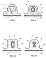
- Figures 8 and 9 show precisely the temperature isotherms recorded during vulcanization of a caterpillar inside a guide tooth according to the state of the technique ( Figure 8) and according to the invention ( Figure 9).
- FIG. 8 corresponds to the recordings made for a guide tooth 5 of a prior art track like that shown in Figure 4.
- Curves C1, C2, C3 are isotherms recorded during vulcanization after a given time T, the curve C1 corresponding to a temperature above C2, C2 corresponding to a temperature above C3.
- FIG. 9 corresponding to the temperature readings after the same time T for a track according to the invention and corresponding to that described with FIGS. 6 and 7, we have made figure the same isotherms C1, C2, C3 inside a guide tooth 50 comprising a hollow insert 16 better thermal conductor than surrounding rubber mixtures.
- the isotherm C2 has reached a part located more inside the tooth (i.e. more close to the frame 60 of the tooth) and that the isotherm C3 is practically entirely located at the armature level 60. This is favorable from an industrial point of view since the vulcanization time of the track according to the invention can be substantially reduced, the innermost parts of the teeth more quickly reaching the desired vulcanization temperature.
- the structure of a tooth according to the invention makes it possible to avoid phenomena of overcooking of the most the outside (i.e. those closest to the mold walls) which are subjected less time to high temperatures compared to the case of a track according to the state of the art.
- FIG. 10 shows in longitudinal section a partial view of a guide tooth 40 according to the invention before molding; this tooth 40 includes an insert 41 made of material colored in the mass and having a shape general hollow cylindrical, not blocked at its axial ends, the cross section of which imperfectly forms the figure "eight" to delimit a volume of depressions 42. Furthermore, the wall thickness of this insert is not constant so as to create front and rear zones 45 and 46 of thickness substantially reduced compared to the thickness of the other zones 43 and 44.
- zones 45, 46 of reduced thickness are comparable to zones of weakness which can deform preferentially compared to the other zones under the action of the forces resulting from the dilation of the mixtures as shown in Figure 11 showing the same tooth 40 after molding and vulcanization of the caterpillar 100. It can be seen that the absorption of the expansion deformation of the mixtures by the deformation of the insert 41 and the reduction in the volume of recesses 42 made it possible to avoid modification of the geometry of the reinforcing reinforcement 47.
- the areas of weakness are located near the upper surface 48 of the guide tooth and / or near reinforcement 47. If each tooth is made up of a plurality of gum mixtures, it is judicious to locate the zones of weakness (and the orifices when there are some) in the vicinity of the mixtures with the highest expansion coefficients.
- each tooth according to the invention comprising both the faces front and rear and side faces, can, and as is widely known and practiced in the notched belts, be reinforced by at least one textile fabric playing the role of protection against external aggressions.
- the invention is not limited to the examples described and shown and various modifications can be made without departing from its scope.
- the application of the invention to relief patterns forming the caterpillar sculpture i.e. the patterns molded on the surface exterior of the strip forming the track
Landscapes
- Engineering & Computer Science (AREA)
- Mechanical Engineering (AREA)
- Chemical & Material Sciences (AREA)
- Combustion & Propulsion (AREA)
- Transportation (AREA)
- Moulds For Moulding Plastics Or The Like (AREA)
- Extrusion Moulding Of Plastics Or The Like (AREA)
- Seal Device For Vehicle (AREA)
- Golf Clubs (AREA)
- Belt Conveyors (AREA)
- Diaphragms For Electromechanical Transducers (AREA)
Applications Claiming Priority (2)
| Application Number | Priority Date | Filing Date | Title |
|---|---|---|---|
| FR0009885 | 2000-07-27 | ||
| FR0009885A FR2812851A1 (fr) | 2000-07-27 | 2000-07-27 | Chenille en caoutchouc |
Publications (2)
| Publication Number | Publication Date |
|---|---|
| EP1176087A1 true EP1176087A1 (de) | 2002-01-30 |
| EP1176087B1 EP1176087B1 (de) | 2004-02-11 |
Family
ID=8853000
Family Applications (1)
| Application Number | Title | Priority Date | Filing Date |
|---|---|---|---|
| EP01117347A Expired - Lifetime EP1176087B1 (de) | 2000-07-27 | 2001-07-18 | Gummiraupenkette |
Country Status (9)
| Country | Link |
|---|---|
| US (1) | US6609770B2 (de) |
| EP (1) | EP1176087B1 (de) |
| JP (1) | JP2002240755A (de) |
| AT (1) | ATE259321T1 (de) |
| AU (1) | AU5767401A (de) |
| BR (1) | BR0103053A (de) |
| CA (1) | CA2353366A1 (de) |
| DE (1) | DE60101982T2 (de) |
| FR (1) | FR2812851A1 (de) |
Cited By (4)
| Publication number | Priority date | Publication date | Assignee | Title |
|---|---|---|---|---|
| EP1336468A3 (de) * | 2002-02-16 | 2004-03-03 | BRECO Antriebstechnik Breher GmbH & Co. | Zahnriemen aus Kunststoff und Verfahren und Vorrichtung zum Herstellen eines Zahnriemens |
| EP2327611A1 (de) * | 2009-11-25 | 2011-06-01 | Veyance Technologies, Inc. | Fahrzeugraupen |
| US9975590B2 (en) | 2016-04-27 | 2018-05-22 | ContiTech Trasportbandsysteme GmbH | Vehicle track |
| FR3155158A1 (fr) * | 2023-11-15 | 2025-05-16 | Imagine | Procédé de fabrication d’une courroie |
Families Citing this family (12)
| Publication number | Priority date | Publication date | Assignee | Title |
|---|---|---|---|---|
| USD549741S1 (en) * | 2006-01-31 | 2007-08-28 | Bridgestone Corporation | Rubber crawler |
| US9199694B2 (en) * | 2010-06-29 | 2015-12-01 | Kimpex Inc. | Slide bar for a track system |
| US9067631B1 (en) * | 2010-12-14 | 2015-06-30 | Camoplast Solideal Inc. | Endless track for traction of a vehicle |
| DE102011118421A1 (de) * | 2011-11-12 | 2013-05-16 | Diehl Defence Land Systems Gmbh | Gleiskette oder Gleiskettensegment |
| US9806046B2 (en) * | 2014-03-13 | 2017-10-31 | Taiwan Semiconductor Manufacturing Co., Ltd | Semiconductor device structure and manufacturing method |
| IT201600096899A1 (it) * | 2016-09-27 | 2018-03-27 | Prinoth Spa | Barra trasversale per cingoli di veicoli battipista |
| US10099734B2 (en) | 2016-11-01 | 2018-10-16 | Contitech Transportbandsysteme Gmbh | Urethane hybrid agricultural vehicle track |
| US10589809B2 (en) | 2016-11-01 | 2020-03-17 | Contitech Transportbandsysteme Gmbh | Urethane hybrid agricultural vehicle track |
| US11738813B2 (en) | 2016-11-01 | 2023-08-29 | Loc Performance Products, Llc | Urethane hybrid agricultural vehicle track |
| JP6866739B2 (ja) * | 2017-04-13 | 2021-04-28 | 住友ゴム工業株式会社 | ゴムクローラ |
| CN110802526A (zh) * | 2019-11-25 | 2020-02-18 | 青岛宏昆精工有限公司 | 高耐磨抛丸机履带 |
| US20230132538A1 (en) * | 2021-11-02 | 2023-05-04 | Soucy International Inc. | Endless track for a track system and track system comprising same |
Citations (6)
| Publication number | Priority date | Publication date | Assignee | Title |
|---|---|---|---|---|
| FR957422A (de) * | 1946-12-24 | 1950-02-20 | ||
| DE1800353A1 (de) * | 1967-12-28 | 1969-07-31 | Scholtz Ag Conrad | Raupenband fuer Schneefahrzeuge |
| GB2209814A (en) * | 1987-09-15 | 1989-05-24 | Rapra Techn Ltd | Fatigue-resistant V-belts |
| EP0351492A2 (de) * | 1988-07-21 | 1990-01-24 | CLOUTH Gummiwerke AG | Verfahren zur Herstellung einer Gleiskette und bei der Durchführung des Verfahrens zu verwendende Gummihülsen |
| EP0893334A1 (de) * | 1997-07-23 | 1999-01-27 | Bridgestone Corporation | Gummiraupe |
| US5984438A (en) | 1996-05-16 | 1999-11-16 | Bridgestone Corporation | Rubber track |
Family Cites Families (7)
| Publication number | Priority date | Publication date | Assignee | Title |
|---|---|---|---|---|
| US3516467A (en) * | 1968-03-19 | 1970-06-23 | Clark D Sims | Tire with automatic wear indicating means |
| US4168393A (en) * | 1977-12-16 | 1979-09-18 | Amerace Corporation | Electrical connector composite housing and method of making same |
| US4535827A (en) * | 1984-03-07 | 1985-08-20 | Wil-Mat Corporation | Molded shock-absorbing wheel assembly |
| US5511869A (en) * | 1991-08-26 | 1996-04-30 | Edwards, Harper, Mcnew & Company | Replacement endless vehicle tracks |
| US5839847A (en) * | 1997-02-21 | 1998-11-24 | Mcdonnell Douglas Corporation | Molded article with captured fasteners |
| US6203125B1 (en) * | 1997-10-03 | 2001-03-20 | Yokohama Rubber Co., Ltd. | Track belt for snowmobile |
| US6220199B1 (en) * | 1999-01-21 | 2001-04-24 | Wildon Williams | Tire with worn tread indicator |
-
2000
- 2000-07-27 FR FR0009885A patent/FR2812851A1/fr active Pending
-
2001
- 2001-07-18 EP EP01117347A patent/EP1176087B1/de not_active Expired - Lifetime
- 2001-07-18 DE DE60101982T patent/DE60101982T2/de not_active Expired - Lifetime
- 2001-07-18 AT AT01117347T patent/ATE259321T1/de not_active IP Right Cessation
- 2001-07-24 CA CA002353366A patent/CA2353366A1/fr not_active Abandoned
- 2001-07-26 BR BR0103053-1A patent/BR0103053A/pt not_active Application Discontinuation
- 2001-07-26 US US09/915,900 patent/US6609770B2/en not_active Expired - Fee Related
- 2001-07-26 AU AU57674/01A patent/AU5767401A/en not_active Abandoned
- 2001-07-27 JP JP2001262382A patent/JP2002240755A/ja active Pending
Patent Citations (6)
| Publication number | Priority date | Publication date | Assignee | Title |
|---|---|---|---|---|
| FR957422A (de) * | 1946-12-24 | 1950-02-20 | ||
| DE1800353A1 (de) * | 1967-12-28 | 1969-07-31 | Scholtz Ag Conrad | Raupenband fuer Schneefahrzeuge |
| GB2209814A (en) * | 1987-09-15 | 1989-05-24 | Rapra Techn Ltd | Fatigue-resistant V-belts |
| EP0351492A2 (de) * | 1988-07-21 | 1990-01-24 | CLOUTH Gummiwerke AG | Verfahren zur Herstellung einer Gleiskette und bei der Durchführung des Verfahrens zu verwendende Gummihülsen |
| US5984438A (en) | 1996-05-16 | 1999-11-16 | Bridgestone Corporation | Rubber track |
| EP0893334A1 (de) * | 1997-07-23 | 1999-01-27 | Bridgestone Corporation | Gummiraupe |
Cited By (6)
| Publication number | Priority date | Publication date | Assignee | Title |
|---|---|---|---|---|
| EP1336468A3 (de) * | 2002-02-16 | 2004-03-03 | BRECO Antriebstechnik Breher GmbH & Co. | Zahnriemen aus Kunststoff und Verfahren und Vorrichtung zum Herstellen eines Zahnriemens |
| EP2327611A1 (de) * | 2009-11-25 | 2011-06-01 | Veyance Technologies, Inc. | Fahrzeugraupen |
| US8567876B2 (en) | 2009-11-25 | 2013-10-29 | Veyance Technologies, Inc. | Vehicle track |
| US9975590B2 (en) | 2016-04-27 | 2018-05-22 | ContiTech Trasportbandsysteme GmbH | Vehicle track |
| FR3155158A1 (fr) * | 2023-11-15 | 2025-05-16 | Imagine | Procédé de fabrication d’une courroie |
| WO2025103618A1 (fr) * | 2023-11-15 | 2025-05-22 | Imagine | Procédé de fabrication d'une courroie |
Also Published As
| Publication number | Publication date |
|---|---|
| AU5767401A (en) | 2002-01-31 |
| JP2002240755A (ja) | 2002-08-28 |
| EP1176087B1 (de) | 2004-02-11 |
| FR2812851A1 (fr) | 2002-02-15 |
| ATE259321T1 (de) | 2004-02-15 |
| BR0103053A (pt) | 2002-02-26 |
| US20020050741A1 (en) | 2002-05-02 |
| CA2353366A1 (fr) | 2002-01-27 |
| DE60101982D1 (de) | 2004-03-18 |
| US6609770B2 (en) | 2003-08-26 |
| DE60101982T2 (de) | 2004-12-30 |
Similar Documents
| Publication | Publication Date | Title |
|---|---|---|
| EP1176087B1 (de) | Gummiraupenkette | |
| EP2627524B1 (de) | Verbesserte geräuschdämpfer für reifen | |
| WO2005123420A1 (fr) | Bande de roulement ayant des incisions zigzag et lames pour le moulage de telles incisions | |
| EP1264713B1 (de) | Lauffläche mit neigungsvariablen Feineinschnitten enthaltenden Rippen | |
| EP3648991B1 (de) | Reifen dessen lauffläche wellenförmige nuten aufweist | |
| FR2759323A1 (fr) | Sculpture de bande de roulement et procede de fabrication | |
| EP3439897B1 (de) | Reifenlauffläche | |
| WO2017174925A1 (fr) | Bande de roulement de pneu | |
| EP1259389B1 (de) | Reifenlaufflächenprofil | |
| EP3297855B1 (de) | Reifen für schwerlastkraftwagen mit verschleissanzeige | |
| EP1901929B1 (de) | Lauffläche mit einem profilmuster mit einschnitten | |
| EP1646514B1 (de) | Laufflächeprofil das mindestens ein eingesetztes element hat | |
| EP3276058B1 (de) | Litze für jacquard-webrahmen, ihr herstellungsverfahren und webrahmen, der eine solche litze umfasst | |
| EP0829658B1 (de) | Treibriemen und der dazugehörige Herstellungsprozess | |
| CA2300506A1 (fr) | Sculpture de bande de roulement et moule | |
| FR2898298A1 (fr) | Incision de bande de roulement comprenant des parties de blocage. | |
| EP1351830A1 (de) | Drehrichtungsgebundene lauffläche mit einschnitten von variabler neigung | |
| FR2672252A1 (fr) | Roue en resine synthetique du type d'une seule piece. | |
| EP3898281B1 (de) | Lauffläche mit durch versetzte öffnungen erweiterten verborgenen hohlräumen | |
| FR2534858A1 (fr) | Motif de bande de roulement pour pneumatique radial pour lourdes charges, par exemple pour metro sur pneus | |
| FR3090479A1 (fr) | Bande de roulement comportant des rainures interrompues. | |
| FR2572425A3 (fr) | Structure composite perfectionnee de roue dentee pour l'actionnement de rubans porte-pinces pour metiers a tisser. |
Legal Events
| Date | Code | Title | Description |
|---|---|---|---|
| PUAI | Public reference made under article 153(3) epc to a published international application that has entered the european phase |
Free format text: ORIGINAL CODE: 0009012 |
|
| AK | Designated contracting states |
Kind code of ref document: A1 Designated state(s): AT BE CH CY DE DK ES FI FR GB GR IE IT LI LU MC NL PT SE TR |
|
| AX | Request for extension of the european patent |
Free format text: AL;LT;LV;MK;RO;SI |
|
| 17P | Request for examination filed |
Effective date: 20020730 |
|
| AKX | Designation fees paid |
Free format text: AT BE CH CY DE DK ES FI FR GB GR IE IT LI LU MC NL PT SE TR |
|
| GRAP | Despatch of communication of intention to grant a patent |
Free format text: ORIGINAL CODE: EPIDOSNIGR1 |
|
| GRAS | Grant fee paid |
Free format text: ORIGINAL CODE: EPIDOSNIGR3 |
|
| GRAA | (expected) grant |
Free format text: ORIGINAL CODE: 0009210 |
|
| AK | Designated contracting states |
Kind code of ref document: B1 Designated state(s): AT BE CH CY DE DK ES FI FR GB GR IE IT LI LU MC NL PT SE TR |
|
| PG25 | Lapsed in a contracting state [announced via postgrant information from national office to epo] |
Ref country code: IE Free format text: LAPSE BECAUSE OF FAILURE TO SUBMIT A TRANSLATION OF THE DESCRIPTION OR TO PAY THE FEE WITHIN THE PRESCRIBED TIME-LIMIT Effective date: 20040211 Ref country code: AT Free format text: LAPSE BECAUSE OF FAILURE TO SUBMIT A TRANSLATION OF THE DESCRIPTION OR TO PAY THE FEE WITHIN THE PRESCRIBED TIME-LIMIT Effective date: 20040211 Ref country code: TR Free format text: LAPSE BECAUSE OF FAILURE TO SUBMIT A TRANSLATION OF THE DESCRIPTION OR TO PAY THE FEE WITHIN THE PRESCRIBED TIME-LIMIT Effective date: 20040211 Ref country code: CY Free format text: LAPSE BECAUSE OF FAILURE TO SUBMIT A TRANSLATION OF THE DESCRIPTION OR TO PAY THE FEE WITHIN THE PRESCRIBED TIME-LIMIT Effective date: 20040211 Ref country code: FI Free format text: LAPSE BECAUSE OF FAILURE TO SUBMIT A TRANSLATION OF THE DESCRIPTION OR TO PAY THE FEE WITHIN THE PRESCRIBED TIME-LIMIT Effective date: 20040211 |
|
| REG | Reference to a national code |
Ref country code: GB Ref legal event code: FG4D Free format text: NOT ENGLISH |
|
| REG | Reference to a national code |
Ref country code: CH Ref legal event code: EP |
|
| REG | Reference to a national code |
Ref country code: IE Ref legal event code: FG4D Free format text: FRENCH |
|
| REF | Corresponds to: |
Ref document number: 60101982 Country of ref document: DE Date of ref document: 20040318 Kind code of ref document: P |
|
| GBT | Gb: translation of ep patent filed (gb section 77(6)(a)/1977) |
Effective date: 20040324 |
|
| PG25 | Lapsed in a contracting state [announced via postgrant information from national office to epo] |
Ref country code: DK Free format text: LAPSE BECAUSE OF FAILURE TO SUBMIT A TRANSLATION OF THE DESCRIPTION OR TO PAY THE FEE WITHIN THE PRESCRIBED TIME-LIMIT Effective date: 20040511 Ref country code: GR Free format text: LAPSE BECAUSE OF FAILURE TO SUBMIT A TRANSLATION OF THE DESCRIPTION OR TO PAY THE FEE WITHIN THE PRESCRIBED TIME-LIMIT Effective date: 20040511 Ref country code: SE Free format text: LAPSE BECAUSE OF FAILURE TO SUBMIT A TRANSLATION OF THE DESCRIPTION OR TO PAY THE FEE WITHIN THE PRESCRIBED TIME-LIMIT Effective date: 20040511 |
|
| PG25 | Lapsed in a contracting state [announced via postgrant information from national office to epo] |
Ref country code: ES Free format text: LAPSE BECAUSE OF FAILURE TO SUBMIT A TRANSLATION OF THE DESCRIPTION OR TO PAY THE FEE WITHIN THE PRESCRIBED TIME-LIMIT Effective date: 20040522 |
|
| PG25 | Lapsed in a contracting state [announced via postgrant information from national office to epo] |
Ref country code: LU Free format text: LAPSE BECAUSE OF NON-PAYMENT OF DUE FEES Effective date: 20040718 |
|
| PG25 | Lapsed in a contracting state [announced via postgrant information from national office to epo] |
Ref country code: MC Free format text: LAPSE BECAUSE OF NON-PAYMENT OF DUE FEES Effective date: 20040731 Ref country code: BE Free format text: LAPSE BECAUSE OF NON-PAYMENT OF DUE FEES Effective date: 20040731 |
|
| REG | Reference to a national code |
Ref country code: IE Ref legal event code: FD4D |
|
| PLBE | No opposition filed within time limit |
Free format text: ORIGINAL CODE: 0009261 |
|
| STAA | Information on the status of an ep patent application or granted ep patent |
Free format text: STATUS: NO OPPOSITION FILED WITHIN TIME LIMIT |
|
| BERE | Be: lapsed |
Owner name: SOC. DE TECHNOLOGIE *MICHELIN Effective date: 20040731 Owner name: S.A. *MICHELIN RECHERCHE ET TECHNIQUE Effective date: 20040731 |
|
| 26N | No opposition filed |
Effective date: 20041112 |
|
| PG25 | Lapsed in a contracting state [announced via postgrant information from national office to epo] |
Ref country code: LI Free format text: LAPSE BECAUSE OF NON-PAYMENT OF DUE FEES Effective date: 20050731 Ref country code: CH Free format text: LAPSE BECAUSE OF NON-PAYMENT OF DUE FEES Effective date: 20050731 |
|
| REG | Reference to a national code |
Ref country code: CH Ref legal event code: PL |
|
| PGFP | Annual fee paid to national office [announced via postgrant information from national office to epo] |
Ref country code: NL Payment date: 20060714 Year of fee payment: 6 |
|
| PGFP | Annual fee paid to national office [announced via postgrant information from national office to epo] |
Ref country code: GB Payment date: 20060720 Year of fee payment: 6 |
|
| BERE | Be: lapsed |
Owner name: S.A. *MICHELIN RECHERCHE ET TECHNIQUE Effective date: 20040731 Owner name: SOC. DE TECHNOLOGIE *MICHELIN Effective date: 20040731 |
|
| PG25 | Lapsed in a contracting state [announced via postgrant information from national office to epo] |
Ref country code: PT Free format text: LAPSE BECAUSE OF NON-PAYMENT OF DUE FEES Effective date: 20040711 |
|
| GBPC | Gb: european patent ceased through non-payment of renewal fee |
Effective date: 20070718 |
|
| NLV4 | Nl: lapsed or anulled due to non-payment of the annual fee |
Effective date: 20080201 |
|
| PG25 | Lapsed in a contracting state [announced via postgrant information from national office to epo] |
Ref country code: NL Free format text: LAPSE BECAUSE OF NON-PAYMENT OF DUE FEES Effective date: 20080201 |
|
| PG25 | Lapsed in a contracting state [announced via postgrant information from national office to epo] |
Ref country code: GB Free format text: LAPSE BECAUSE OF NON-PAYMENT OF DUE FEES Effective date: 20070718 |
|
| PGFP | Annual fee paid to national office [announced via postgrant information from national office to epo] |
Ref country code: IT Payment date: 20080723 Year of fee payment: 8 |
|
| PGFP | Annual fee paid to national office [announced via postgrant information from national office to epo] |
Ref country code: DE Payment date: 20100723 Year of fee payment: 10 Ref country code: FR Payment date: 20100805 Year of fee payment: 10 |
|
| PG25 | Lapsed in a contracting state [announced via postgrant information from national office to epo] |
Ref country code: IT Free format text: LAPSE BECAUSE OF NON-PAYMENT OF DUE FEES Effective date: 20090718 |
|
| REG | Reference to a national code |
Ref country code: FR Ref legal event code: ST Effective date: 20120330 |
|
| PG25 | Lapsed in a contracting state [announced via postgrant information from national office to epo] |
Ref country code: FR Free format text: LAPSE BECAUSE OF NON-PAYMENT OF DUE FEES Effective date: 20110801 Ref country code: DE Free format text: LAPSE BECAUSE OF NON-PAYMENT OF DUE FEES Effective date: 20120201 |
|
| REG | Reference to a national code |
Ref country code: DE Ref legal event code: R119 Ref document number: 60101982 Country of ref document: DE Effective date: 20120201 |