EP1176237A1 - Webschaft mit Litzendämpfungsvorrichtung für Webmaschine sowie Litzendämpfungsvorrichtung - Google Patents
Webschaft mit Litzendämpfungsvorrichtung für Webmaschine sowie Litzendämpfungsvorrichtung Download PDFInfo
- Publication number
- EP1176237A1 EP1176237A1 EP01440233A EP01440233A EP1176237A1 EP 1176237 A1 EP1176237 A1 EP 1176237A1 EP 01440233 A EP01440233 A EP 01440233A EP 01440233 A EP01440233 A EP 01440233A EP 1176237 A1 EP1176237 A1 EP 1176237A1
- Authority
- EP
- European Patent Office
- Prior art keywords
- heald
- profile
- support
- support profile
- play
- Prior art date
- Legal status (The legal status is an assumption and is not a legal conclusion. Google has not performed a legal analysis and makes no representation as to the accuracy of the status listed.)
- Granted
Links
- 238000013016 damping Methods 0.000 title claims description 46
- 238000009941 weaving Methods 0.000 claims description 22
- 238000004026 adhesive bonding Methods 0.000 claims description 3
- 239000000872 buffer Substances 0.000 abstract description 5
- 239000000853 adhesive Substances 0.000 abstract description 3
- 230000001070 adhesive effect Effects 0.000 abstract description 3
- 239000002131 composite material Substances 0.000 description 12
- 230000035939 shock Effects 0.000 description 12
- 239000006096 absorbing agent Substances 0.000 description 6
- 230000008901 benefit Effects 0.000 description 6
- 239000007769 metal material Substances 0.000 description 6
- 230000000694 effects Effects 0.000 description 4
- 239000000463 material Substances 0.000 description 4
- 229910000838 Al alloy Inorganic materials 0.000 description 3
- 229920001971 elastomer Polymers 0.000 description 3
- 239000000806 elastomer Substances 0.000 description 3
- 239000000835 fiber Substances 0.000 description 3
- 238000013519 translation Methods 0.000 description 3
- OKTJSMMVPCPJKN-UHFFFAOYSA-N Carbon Chemical compound [C] OKTJSMMVPCPJKN-UHFFFAOYSA-N 0.000 description 2
- 229920000049 Carbon (fiber) Polymers 0.000 description 2
- XAGFODPZIPBFFR-UHFFFAOYSA-N aluminium Chemical compound [Al] XAGFODPZIPBFFR-UHFFFAOYSA-N 0.000 description 2
- 229910052782 aluminium Inorganic materials 0.000 description 2
- 229910052799 carbon Inorganic materials 0.000 description 2
- 239000004917 carbon fiber Substances 0.000 description 2
- 238000013461 design Methods 0.000 description 2
- 238000003780 insertion Methods 0.000 description 2
- 230000037431 insertion Effects 0.000 description 2
- 238000000034 method Methods 0.000 description 2
- 230000002028 premature Effects 0.000 description 2
- 230000003068 static effect Effects 0.000 description 2
- 230000009471 action Effects 0.000 description 1
- 238000013459 approach Methods 0.000 description 1
- 230000006399 behavior Effects 0.000 description 1
- 238000005452 bending Methods 0.000 description 1
- 238000010276 construction Methods 0.000 description 1
- 230000007547 defect Effects 0.000 description 1
- 238000006073 displacement reaction Methods 0.000 description 1
- 238000001125 extrusion Methods 0.000 description 1
- 239000011521 glass Substances 0.000 description 1
- 239000003365 glass fiber Substances 0.000 description 1
- 239000003292 glue Substances 0.000 description 1
- 238000004519 manufacturing process Methods 0.000 description 1
- 230000007246 mechanism Effects 0.000 description 1
- 238000012986 modification Methods 0.000 description 1
- 230000004048 modification Effects 0.000 description 1
- 229920000642 polymer Polymers 0.000 description 1
- 238000002360 preparation method Methods 0.000 description 1
- 230000008439 repair process Effects 0.000 description 1
- 238000005096 rolling process Methods 0.000 description 1
- 238000009987 spinning Methods 0.000 description 1
- 239000010935 stainless steel Substances 0.000 description 1
- 229910001220 stainless steel Inorganic materials 0.000 description 1
Images



Classifications
-
- D—TEXTILES; PAPER
- D03—WEAVING
- D03C—SHEDDING MECHANISMS; PATTERN CARDS OR CHAINS; PUNCHING OF CARDS; DESIGNING PATTERNS
- D03C9/00—Healds; Heald frames
- D03C9/06—Heald frames
- D03C9/0608—Construction of frame parts
- D03C9/0616—Horizontal upper or lower rods
- D03C9/0633—Heald bars or their connection to other frame parts
-
- D—TEXTILES; PAPER
- D03—WEAVING
- D03C—SHEDDING MECHANISMS; PATTERN CARDS OR CHAINS; PUNCHING OF CARDS; DESIGNING PATTERNS
- D03C9/00—Healds; Heald frames
- D03C9/06—Heald frames
- D03C9/0691—Arrangements of means for damping or noise reduction
Definitions
- the present invention relates to a heald frame for a weaving machine equipped a heald damping device, this frame comprising an upper profile provided an upper smooth rod, a lower profile provided with a rod bottom rails, two lateral uprights assembled to said profiles to form said frame and weaving healds mounted on said heald rods by their loop-shaped ends, the heald damper being mounted on the at least one of the profiles of the heald frame and positioned in an existing gap between said profile and the rod carry smooth so as to cushion the head of the loops smooth.
- the invention also relates to a heald damping device intended for equip a heald frame.
- the ends of the weaving healds have a loop shape and are mounted on the smooth rods with an imposed operating clearance of approximately 3 mm. This play is necessary for several reasons.
- the introduction of warp threads in the eyelet of the weaving heddles is generally carried out automatically by a adequate retracting machine, this game allowing the healds to line up automatically.
- the weaving heddles must be able to slide freely along the smooth rods to allow the weaver to intervene in the chain son ply, for example to repair a wire after breakage.
- This game is also necessary to avoid any risk of blockage of the beams in relation to smooth rods taking into account manufacturing tolerances and the effects of expansion.
- the very strong excitement of the frames in vibration mode requires the presence of this operating clearance without which the ends of the beams of weaving would break very quickly.
- the heald frames evolve like a mass structure variable with the effect of chain tension and the effect of inertia, sometimes the beam is in support on the upper rod, sometimes it is supported on the lower rod, sometimes it is free between the two support positions.
- the frame cycles full back and forth, there is shock and rebound at the loops smooth. With the speeds reached today, these very strong shocks cause a premature wear of the smooth door rods and untimely breaking of the buckles smooth.
- the solution proposed in publication JP-A-10 001844 provides for a device mounted between one of the profiles of the heald frame and the heald heads in the form a brush. This device makes it possible to limit the lateral displacement of the beams but in no case of damping the movement in vertical translation of the beams.
- Publication WO-A-01/48284 also proposes a solution by reporting a damping element directly on the profiles of the heald frame, these profiles being commonly made of extruded or extruded aluminum alloy.
- This solution does can be envisaged only with profiles made of a metallic material which have a controllable and acceptable straightness in order to guarantee a play of operation between the boom heads and the constant damping element over the entire frame length.
- this solution is not at all suitable for profiles heald frame made of composite materials (carbon fibers or others) including the straightness is much less good.
- the operating clearance between the heald heads and the damping element cannot be constant over the entire frame length, the boom of a composite material profile reaching for example 4 mm by 3 m in length.
- this solution does not allow adjust the clearance between the damping element and the heald heads, in particular to lock the heddles in normal operation of the loom.
- the purpose of the present invention is to overcome these drawbacks by proposing a simple shock absorber device, easy and quick to install, respecting the play of operation of the weaving heddles, in no way affecting their freedom of movement on the smooth rods, which can be mounted as a kit on frames heald already existing and particularly suitable for heald frames made in composite materials.
- a heald frame as defined in the preamble and characterized in that that the damping device comprises a support profile extending over the entire length of said heald frame profile and comprising at least one flexible element extending over the entire length of the support profile and forming a stopper arranged in look of said head of heald curls.
- This damping device is particularly designed to provide a clearance J 'between said damping device and the head of the heald loops lower than the clearance operation J between the healds and the heald rods.
- the damping device may include means for adjusting said clearance J ′, these adjustment means possibly comprising at least one profile intermediate mounted in said support profile, an adjusting member being arranged between them and movable between at least one position called “with play” and a position called “Without play”.
- the support profile or the intermediate profile preferably has a groove longitudinal arranged to receive by interlocking said flexible element, which can be interchangeable.
- This flexible element may have an inverted T section, the leg of the T being arranged to be housed in said longitudinal groove by socket and the branch T having a profile opposite said head of the heald loops in hollow, in relief or plan.
- the flexible element may also have a circular section arranged to be housed in said longitudinal groove by interlocking.
- the support profile is fixed integrally to said profile by bonding.
- the positioning template can include a positioning template arranged to precisely position said support profile on said profile before bonding while respecting the clearance J ′.
- the positioning template has positioning clips, each provided of two notches corresponding respectively to said support profile and to said smooth rod.
- the support profile and the smooth support rod can be formed in one piece.
- the clearance J ' is determined by said support profile.
- the heald frame may include two shock absorbers provided respectively on the upper profile and on the profile lower of said heald frame.
- a heald damping device characterized in that that it comprises a support profile provided with a longitudinal groove arranged to receiving by interlocking a projecting flexible element forming a stop for the head heald curls.
- it may include a positioning template arranged to precisely mount said support profile on the heald frame in respecting the clearance J ', this template consisting of positioning clips, each being provided with two notches arranged to receive the profile respectively support and the smooth rod.
- the support profile may include a side wall from which a smooth rod protrudes, the clearance J 'being determined by said support profile.
- the support profile may include means for adjusting said clearance J ′, these adjustment means possibly comprising at least one profile intermediate mounted in said support profile, an adjusting member being arranged between them and movable between at least one position called “with play” and a position called “Without play”.
- this heald frame 1 for a machine to weave.
- this heald frame 1 comprises an upper profile 2 provided with an upper smooth rod 3, a lower profile 4 provided with a lower heald rod 5, two lateral uprights 6, 7 assembled to the said profiles 2, 4 to form said frame.
- This heald frame 1 is preferably made of composite materials, for example based on carbon fibers, glass or other fibers. Composite materials have the advantage of giving the heald frame 1 a excellent mechanical resistance to fatigue while considerably reducing its weight. Of course, the heald frame 1 can be made of any other suitable material. The method of assembling said heald frame 1 is not detailed since it is not the subject of the present invention.
- each stringer carries a set of weaving heddles 8, only two of which are shown, mounted on the smooth rods 3, 5 by their ends 9 in the form of a loop, in respecting an operating clearance J of approximately 3 mm.
- each stringer carries an eyelet 10 for the passage of a chain wire 11 (cf. fig. 2).
- They are generally made of a hardened metallic material to resist stresses mechanical.
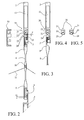
- the heald frame 1 is advantageously supplemented by a device heald damper 20 with reference to FIGS. 2 to 5.
- This damping device for smooth 20 is provided, in the examples shown, on the upper profile 2, but can also be placed on the lower profile 4 or on the two profiles, depending on the case.
- the upper profile 2 has a substantially rectangular section 12, elongated and extended by a rear wall 13 on which the rod carries smooth upper 3 protrudes, T-shaped lying.
- the smooth support rod 3 is made in one piece with the profile (s) 2, 4 or is an insert, for example by gluing, whether or not completed with rivets or by any other equivalent fixing means.
- This rod carries smooth 3 receives the loop upper 9 of the stringer 8, which has a C shape and is commonly called "tex boom loop". Between the upper edge of the heald rod 3 and the edge lower section 12 of profile 2 there is a gap 14 sufficient to accommodate it said damping device 20. It is therefore positioned above the head of the loop of the heald 9 and is designed to absorb the shocks of the weave heald 8.
- FIG. 2 represents the weaving smooth 8 in static mode where it is supported on the upper heald rod 3.
- the operating clearance J of approximately 3 mm is visible on the lower heald rod 5.
- the damping device 20 introduces a clearance J 'of approximately 0.5 to 1 mm visible between the damping device 20 and the head of the heald loop 9. Thanks to this configuration, the damping device 20 does not hinder not the freedom of the weaving smooth 8 in static mode, which remains mobile along the rods 3 and 5. It is only in dynamic mode that the damping device 20 is used and fully fulfills its role by limiting the operating clearance J of the boom 8 at clearance J 'and by damping the head of the heald loop 9 if the heald travel is greater than 1mm.
- the damping device 20 comprises a profile support 21 of small section and extending over the entire length of the upper profile 2 heald frame 1. It is, for example, made of extruded aluminum or in any other equivalent material. It has an approximately square section and dimensions such as to be housed in the interval 14. It has in its lower edge a longitudinal groove 22 for receiving a flexible element 23 forming a stopper, made for example in a polymer, an elastomer, a composite material or any other equivalent material, chosen to resist vibration frequencies and to the efforts to bear.
- This stopper 23 may have an inverted T section, the leg of the T being housed in the longitudinal groove 22 by fitting and the bar of the T being curved for example to approximate the roundness of the top of the heald loop 9.
- the contact surfaces between the stopper 23 and the support profile 21 are perpendicular to the orientation of the heddle 8 and therefore to the orientation of the shocks for avoid any risk of accidental release of the stopper 23 from the groove longitudinal 22.
- the support profile 21 is an integral part of the profile superior 2 and remains permanently.
- the stopper 23 can easily be put in and out of the groove 22 when it must be changed, without any difficulty.
- Figure 3 illustrates another embodiment of Figure 2.
- the rod smooth door 3 ' has, in this variant, a G shape in which a loop is housed 9 'smooth G in inverted G, commonly called "extra smooth loop".
- the damping device 20 is similar to the previous one. The only difference is the shape of the stopper 24, which has, in this variant, a circular section.
- the clips of positioning 30 are of course adapted to this variant embodiment, in particular the housing 32 relative to the smooth rod 3 '.
- Figures 4 and 5 illustrate two other embodiments of the device shock absorber 20 in which the stopper 25, 26 has an inverted T section, the branch of the T being respectively straight and conical.
- the stopper 25, 26 has an inverted T section, the branch of the T being respectively straight and conical.
- other forms of bumper can be considered as needed.
- other profile sections support 21 and groove 22 can be envisaged depending on the section and the dimensions of the interval 14 available.
- Figures 6 to 8 illustrate a first alternative embodiment of the device heald damper 20 'according to the invention.
- the rod carries smooth 30, 30 'is not integrated into the upper 2' and / or lower profiles of the heald frame 1 but directly to the support profile 21 'of the damping device 20'.
- the profiles 2 'of the heald frame 1 are extended, after the section elongated rectangular 12, by a substantially planar rear wall 13 'arranged to receive the support profile 21 '.
- This support profile 21 ' has a side wall 27 from which protrudes a smooth rod 30, 30 '.
- This rod carries smooth 30, 30 'has a shape of T lying down, a form of G depending on whether it is intended to carry stringers whose loops are respectively of the "Tex" or "Extra” type.
- the outer shape of the side wall 27 of the support profile 21 ' is such that it complements the shape inside of the rear wall 13 ′ of the profile 2 ′ of the heald frame 1.
- the support profile 21 ' has, as in the previous example, a groove longitudinal 22 for receiving a flexible element 24 forming a stopper.
- This bumper 24 may have a circular section or a section conforming to the stops 23, 25 or 26 described above or any other suitable section.
- This support profile 21 ' can be made of aluminum or aluminum alloy obtained by spinning or extrusion, mainly for reasons of lightness and cost.
- the smooth support rod 30 ′ can be covered with a glued cover 28 or clipped made, for example, of stainless steel to guarantee good resistance to the wear of this rod carries smooth 30 '.
- Figures 9 and 10 illustrate a second alternative embodiment of the device heald damper 200 according to the invention.
- the device shock absorber 200 is arranged to allow adjustment of the clearance J '.
- It has a profile support 210, which as in the example with reference to FIGS. 6 to 8, is extended by a side wall 27 from which protrudes a smooth rod 30 'in the form of G which makes it possible to wear stringers whose loops 9 'are of the "Extra" type.
- this support profile 210 can also be equipped with a rod Smooth door 30 in the shape of a T lying to wear smooth whose curls are type "Tex".
- this support profile 210 may not integrate the rod smooth door as in the embodiment with reference to Figures 2 to 5.
- This support profile 210 is completed by an intermediate profile 220 which comprises a longitudinal groove 22 for receiving a flexible element 24 forming a stopper.
- This stopper 24 has a circular section but can also have a conforming section to the buffers 23, 25 or 26 described with reference to Figures 2, 4 and 5.
- This intermediate section 220 has a rib 221 in the shape of an inverted L, this rib being housed in an inverted G-shaped rail 211 formed in the profile support 210.
- a flexible cord 222 for example made of elastomer, is inserted between the bottom of rail 211 and rib 221 and an adjusting member 223 is positioned between the the branches of L and G respectively of the rib 221 and of the rail 211.
- This member adjuster 223 has an elliptical shape and is coupled to a control member (not shown) which allows it to be moved between two stable positions: a position called "with play” and a position called "without play".
- the control unit can be manual and operated by the weaver or automatic and linked to the operating mode of the loom.
- the largest diameter of the adjusting member 223 is oriented vertically, which goes up the intermediate profile 220 inside the support profile 210 and provides a clearance J ' between the stopper 24 and the heads of the heald loops 9 '.
- This position is particularly suitable for easily and quickly retracting smooth 8 as well as the retraction of the chain son by a retraction machine automatic.
- the largest diameter of the adjusting member 223 is oriented horizontally, which descends the intermediate profile 220 outside the support profile 210 and eliminates the play J ' between the stopper 24 and the heads of the heald loops 9 '.
- This position is particularly suitable during normal operation of the loom.
- the heads of the upper heald loops 9 ′ are thus blocked in vertical translation this which makes it possible to reduce even more effectively the breakage of the heald loops and the noise pollution due to vibrations.
- clearance J is kept between the heald loops 9, 9 'and the bottom heald rod 5, which allows the weaver to intervene between the beams if necessary, the beams being able to pivot around their upper fixed point.
- the damping device 20, 20 ′, 200 is simple, easy to produce and to assemble, economical, reliable and allows to solve problems effectively wear and premature breakage of the heald loops, wear of the heald rods, also reducing the noise level of weaving machines.
- the heald frames remain fully compatible with automatic wire take-in machines chain and with the requirements of the weavers concerning the mobility of the heddles.
- Another advantage lies in the very design of the damping device 20, 20 ', 200 by a support profile 21, 21 ', 210 attached to the profile (s) 2, 4 of the frame smooth 1 and not directly integrated into these profiles.
- This original construction allows to make the damping device 20, 20 ', 200 fully compatible with heald frames made of composite materials, for example based on carbon, glass fiber or other fibers.
- the support profile 21, 21 'being made of a spun or extruded metallic material has a straightness perfectly controlled which compensates for the lack of straightness of the profiles 2, 4 of the heald frame 1 encountered with technical materials.
- Figures 11 and 12 schematically represent a profile 2, 4 of heald frame 1 made respectively of metallic materials and composite materials.
- the extruded or extruded profile 2, 4 for example in an aluminum alloy has perfect linearity to within a few tenths.
- the interval 14 existing between the section 12 of the section 2, 4 and the rod smooth door 3, 3 ', 5 is constant over the entire length of the profile 2, 4 ranging from 1m to 4m.
- the profile 2, 4 extruded or spun in composite materials has a linearity defect intentionally exaggerated.
- the interval 14 is variable over the entire length of the profile 2, 4 and the rod smooth 3, 3 ', 5 produced by rolling a metallic material ensures this linearity essential for beams 8.
- heald frame 1 It is important to remember that the function essential of the profiles 2, 4 of a heald frame 1 is to provide the mechanical strength to bending of the smooth door rod 3, 3 ', 5 while reducing the weight of the frame and increasing its capacity for resistance to mechanical fatigue. This is why heald frames made of composite materials allow this function to be fulfilled in a completely efficient and optimal way.
- This new damping device 20, 20 ', 200 avoids this inconvenience thanks to the principle of the adjustable play on the upper rod and in particular in its “play-free” position for the device 200.
- This damping device 20, 20 ′, 200 can of course be offered for sale or directly integrated into new heald frames, either as a kit to equip already existing heald frames.
Landscapes
- Engineering & Computer Science (AREA)
- Textile Engineering (AREA)
- Looms (AREA)
- Audible-Bandwidth Dynamoelectric Transducers Other Than Pickups (AREA)
- Automobile Manufacture Line, Endless Track Vehicle, Trailer (AREA)
Applications Claiming Priority (2)
| Application Number | Priority Date | Filing Date | Title |
|---|---|---|---|
| FR0009757 | 2000-07-24 | ||
| FR0009757A FR2812007B1 (fr) | 2000-07-24 | 2000-07-24 | Cadre de lisse pour machine a tisser equipe d'un dispositif amortisseur de lisses et dispositif amortisseur de lisses |
Publications (2)
| Publication Number | Publication Date |
|---|---|
| EP1176237A1 true EP1176237A1 (de) | 2002-01-30 |
| EP1176237B1 EP1176237B1 (de) | 2003-10-15 |
Family
ID=8852906
Family Applications (1)
| Application Number | Title | Priority Date | Filing Date |
|---|---|---|---|
| EP01440233A Expired - Lifetime EP1176237B1 (de) | 2000-07-24 | 2001-07-23 | Webschaft mit Litzendämpfungsvorrichtung für Webmaschine sowie Litzendämpfungsvorrichtung |
Country Status (4)
| Country | Link |
|---|---|
| EP (1) | EP1176237B1 (de) |
| AT (1) | ATE252168T1 (de) |
| DE (1) | DE60100974D1 (de) |
| FR (1) | FR2812007B1 (de) |
Cited By (7)
| Publication number | Priority date | Publication date | Assignee | Title |
|---|---|---|---|---|
| FR2835853A1 (fr) * | 2002-02-14 | 2003-08-15 | Grob Horgen Ag | Lisse ainsi que lame utilisant une telle lisse et procede de fonctionnement d'une telle lame |
| WO2004057077A1 (de) * | 2002-12-19 | 2004-07-08 | Groz-Beckert Kg | Schaftrahmen und webschaft für webmaschinen |
| WO2005001179A1 (de) * | 2003-06-28 | 2005-01-06 | Groz-Beckert Kg | Schaftstab mit beweglichem litzendämpfungselement |
| WO2005040468A1 (de) * | 2003-10-21 | 2005-05-06 | Picanol N.V. | Webschaft |
| EP3406772A1 (de) * | 2017-05-22 | 2018-11-28 | Groz-Beckert KG | Schaftstab und webschaft |
| IT201900009114A1 (it) | 2019-06-17 | 2020-12-17 | Itema Spa | Quadro-liccio per telai di tessitura comprendente un dispositivo di frenatura del movimento per inerzia delle maglie nelle fasi di inversione di moto del quadro-liccio |
| JP2021134451A (ja) * | 2020-02-27 | 2021-09-13 | ナンカイ工業株式会社 | フレームスティーブ、ヘルドフレーム、ダンパー、及び、織機 |
Citations (8)
| Publication number | Priority date | Publication date | Assignee | Title |
|---|---|---|---|---|
| US2522043A (en) * | 1947-09-27 | 1950-09-12 | Steel Heddle Mfg Co | Loom harness |
| US3895655A (en) * | 1974-04-12 | 1975-07-22 | Rockwell International Corp | Harness frame for looms |
| US4106529A (en) * | 1976-10-22 | 1978-08-15 | Steel Heddle Manufacturing Company | Heddle frame |
| US4259995A (en) * | 1978-07-13 | 1981-04-07 | Yoshida Kogyo K. K. | Harness for looms |
| WO1997026396A1 (de) * | 1996-01-19 | 1997-07-24 | Picanol N.V. | Webschaft für eine webmaschine |
| JPH101844A (ja) * | 1996-06-14 | 1998-01-06 | Tsudakoma Corp | 織機用ヘルドフレーム |
| JPH1136154A (ja) * | 1997-07-10 | 1999-02-09 | Kashiyuu Kogyo Kk | 綜絖枠におけるヘルドの配列装置 |
| WO2001048284A1 (de) * | 1999-12-24 | 2001-07-05 | Picanol N.V. | Webschaft für eine webmaschine |
-
2000
- 2000-07-24 FR FR0009757A patent/FR2812007B1/fr not_active Expired - Fee Related
-
2001
- 2001-07-23 EP EP01440233A patent/EP1176237B1/de not_active Expired - Lifetime
- 2001-07-23 DE DE60100974T patent/DE60100974D1/de not_active Expired - Lifetime
- 2001-07-23 AT AT01440233T patent/ATE252168T1/de not_active IP Right Cessation
Patent Citations (8)
| Publication number | Priority date | Publication date | Assignee | Title |
|---|---|---|---|---|
| US2522043A (en) * | 1947-09-27 | 1950-09-12 | Steel Heddle Mfg Co | Loom harness |
| US3895655A (en) * | 1974-04-12 | 1975-07-22 | Rockwell International Corp | Harness frame for looms |
| US4106529A (en) * | 1976-10-22 | 1978-08-15 | Steel Heddle Manufacturing Company | Heddle frame |
| US4259995A (en) * | 1978-07-13 | 1981-04-07 | Yoshida Kogyo K. K. | Harness for looms |
| WO1997026396A1 (de) * | 1996-01-19 | 1997-07-24 | Picanol N.V. | Webschaft für eine webmaschine |
| JPH101844A (ja) * | 1996-06-14 | 1998-01-06 | Tsudakoma Corp | 織機用ヘルドフレーム |
| JPH1136154A (ja) * | 1997-07-10 | 1999-02-09 | Kashiyuu Kogyo Kk | 綜絖枠におけるヘルドの配列装置 |
| WO2001048284A1 (de) * | 1999-12-24 | 2001-07-05 | Picanol N.V. | Webschaft für eine webmaschine |
Non-Patent Citations (2)
| Title |
|---|
| PATENT ABSTRACTS OF JAPAN vol. 1998, no. 05 30 April 1998 (1998-04-30) * |
| PATENT ABSTRACTS OF JAPAN vol. 1999, no. 05 31 May 1999 (1999-05-31) * |
Cited By (14)
| Publication number | Priority date | Publication date | Assignee | Title |
|---|---|---|---|---|
| BE1017499A3 (fr) * | 2002-02-14 | 2008-11-04 | Grob Horgen Ag | Lisse ainsi que lame utilisant une telle lisse et procede de fonctionnement d'une telle lame. |
| DE10206130B4 (de) * | 2002-02-14 | 2016-09-01 | Groz-Beckert Kg | Webschaft mit mindestens einer Weblitze |
| FR2835853A1 (fr) * | 2002-02-14 | 2003-08-15 | Grob Horgen Ag | Lisse ainsi que lame utilisant une telle lisse et procede de fonctionnement d'une telle lame |
| WO2004057077A1 (de) * | 2002-12-19 | 2004-07-08 | Groz-Beckert Kg | Schaftrahmen und webschaft für webmaschinen |
| US8146621B2 (en) | 2002-12-19 | 2012-04-03 | Groz-Beckert Kg | Metal heald frame and heald shaft for a loom |
| CN1820099B (zh) * | 2003-06-28 | 2011-04-06 | 格罗兹-贝克特公司 | 具有可动综丝阻尼件的综框杆条 |
| US7322383B2 (en) | 2003-06-28 | 2008-01-29 | Groz-Beckert Kg | Heald frame rod comprising a displaceable heald damping element |
| WO2005001179A1 (de) * | 2003-06-28 | 2005-01-06 | Groz-Beckert Kg | Schaftstab mit beweglichem litzendämpfungselement |
| CN1871383B (zh) * | 2003-10-21 | 2011-11-30 | 必佳乐有限公司 | 综框 |
| WO2005040468A1 (de) * | 2003-10-21 | 2005-05-06 | Picanol N.V. | Webschaft |
| EP3406772A1 (de) * | 2017-05-22 | 2018-11-28 | Groz-Beckert KG | Schaftstab und webschaft |
| IT201900009114A1 (it) | 2019-06-17 | 2020-12-17 | Itema Spa | Quadro-liccio per telai di tessitura comprendente un dispositivo di frenatura del movimento per inerzia delle maglie nelle fasi di inversione di moto del quadro-liccio |
| EP3754065A1 (de) | 2019-06-17 | 2020-12-23 | ITEMA S.p.A. | Schaftrahmen für webmaschinen mit einer bremsvorrichtung der schaftbewegung durch trägheit während der bewegungsumkehrphasen der schaftrahmen |
| JP2021134451A (ja) * | 2020-02-27 | 2021-09-13 | ナンカイ工業株式会社 | フレームスティーブ、ヘルドフレーム、ダンパー、及び、織機 |
Also Published As
| Publication number | Publication date |
|---|---|
| ATE252168T1 (de) | 2003-11-15 |
| EP1176237B1 (de) | 2003-10-15 |
| FR2812007A1 (fr) | 2002-01-25 |
| DE60100974D1 (de) | 2003-11-20 |
| FR2812007B1 (fr) | 2002-11-29 |
Similar Documents
| Publication | Publication Date | Title |
|---|---|---|
| BE1017499A3 (fr) | Lisse ainsi que lame utilisant une telle lisse et procede de fonctionnement d'une telle lame. | |
| EP1176237B1 (de) | Webschaft mit Litzendämpfungsvorrichtung für Webmaschine sowie Litzendämpfungsvorrichtung | |
| EP0823501A1 (de) | Verfahren und Vorrichtung zur Wahl der beweglichen Haken einer Fachbildungsvorrichtung sowie Jacquardwebmaschine | |
| EP1498521B1 (de) | Schaftrahmen und Webmaschine versehen mit mindestens einem solchen Schaftrahmen | |
| EP1876273A1 (de) | Greifer, sein Herstellungsverfahren, Vorrichtung zum Eintragen von Schussfäden, die mit einem solchen Greifer ausgestattet ist, und Webmaschine mit einer derartigen Vorrichtung | |
| EP1413657B1 (de) | Fachbildungsmechanismus und Webmaschinen mit einem solchen Mechanismus | |
| FR2888256A1 (fr) | Dispositif d'accrochage entre elements d'un dispositif de formation de la foule, son procede de fabrication et procede d'accrochage au moyen d'un tel dispositif | |
| EP1852531B1 (de) | Mechanismus zur Bildung des Webfachs, mit einem solchen Mechanismus ausgestattete Webmaschine und Verfahren zur Auswahl der beweglichen Haken in einem solchen Mechanismus | |
| BE1017580A3 (fr) | Dispositif pour la formation de la foule en utilisant des fils de lisiere dans un metier a tisser. | |
| FR3037601A1 (fr) | Lame d'entrainement de crochets appartenant a une mecanique jacquard et mecanique jacquard comprenant une telle lame | |
| EP1350877A1 (de) | Weblitze und Verfahren zu ihrer Herstellung, Fachbildungsvorrichtung und Webmaschine mit einer solchen Weblitze | |
| EP1646743B1 (de) | Webschaft und damit ausgerüstete webmaschine | |
| EP0915195B1 (de) | Vorrichtung zur Verbindung einer Weblitze mit einer Harnischkordel, Weblitze mit einer solchen Vorrichtung sowie Webmaschine mit einer solchen Weblitze | |
| FR2529588A1 (fr) | Ensemble extrude pour barre de lame de metier a tisser | |
| FR3062413A1 (fr) | Amortisseur pour maintenir la tension d'une toile enroulable d'un pare-soleil et pare-soleil equipe de la sorte | |
| EP1540056B1 (de) | Webschaft und damit ausgerüstete webmaschine | |
| EP1331293A1 (de) | Herstellungsverfahren eines Schaftstabs für einen Schaftrahmen einer Webmaschine und ein durch dieses Verfahren hergestellter Schaftstab | |
| EP1646742B1 (de) | Webschaft und mit mindestens einem davon ausgerüstete webmaschine | |
| EP1830073A1 (de) | Vorrichtung zum Befestigen von zwei aneinanderliegenden Teilen mittels einer Klammer | |
| WO1998024956A1 (fr) | Dispositif amortisseur pour ressort de lisse de metier a tisser jacquard | |
| FR2464320A1 (fr) | Organe d'insertion du fil de trame dans les metiers a tisser avec prelevement du fil de trame a partir de bobines fixes | |
| EP1433883B1 (de) | Litze und Litzen-Rahmen für Webstuhl | |
| FR2557084A1 (fr) | Dispositif de main courante, notamment pour un systeme de transport tel qu'un escalier roulant ou analogue | |
| FR2857674A1 (fr) | Cadre de lisse et metier a tisser pourvu d'au moins un tel cadre | |
| FR2826985A1 (fr) | Dispositif amortisseur pour ressort de lisse de metier a tisser jacquard |
Legal Events
| Date | Code | Title | Description |
|---|---|---|---|
| PUAI | Public reference made under article 153(3) epc to a published international application that has entered the european phase |
Free format text: ORIGINAL CODE: 0009012 |
|
| AK | Designated contracting states |
Kind code of ref document: A1 Designated state(s): AT BE CH CY DE DK ES FI FR GB GR IE IT LI LU MC NL PT SE TR |
|
| AX | Request for extension of the european patent |
Free format text: AL;LT;LV;MK;RO;SI |
|
| 17P | Request for examination filed |
Effective date: 20020626 |
|
| AKX | Designation fees paid |
Free format text: AT BE CH CY DE DK ES FI FR GB GR IE IT LI LU MC NL PT SE TR |
|
| 17Q | First examination report despatched |
Effective date: 20021014 |
|
| GRAH | Despatch of communication of intention to grant a patent |
Free format text: ORIGINAL CODE: EPIDOS IGRA |
|
| GRAS | Grant fee paid |
Free format text: ORIGINAL CODE: EPIDOSNIGR3 |
|
| GRAA | (expected) grant |
Free format text: ORIGINAL CODE: 0009210 |
|
| AK | Designated contracting states |
Kind code of ref document: B1 Designated state(s): AT BE CH CY DE DK ES FI FR GB GR IE IT LI LU MC NL PT SE TR |
|
| PG25 | Lapsed in a contracting state [announced via postgrant information from national office to epo] |
Ref country code: TR Free format text: LAPSE BECAUSE OF FAILURE TO SUBMIT A TRANSLATION OF THE DESCRIPTION OR TO PAY THE FEE WITHIN THE PRESCRIBED TIME-LIMIT Effective date: 20031015 Ref country code: IE Free format text: LAPSE BECAUSE OF FAILURE TO SUBMIT A TRANSLATION OF THE DESCRIPTION OR TO PAY THE FEE WITHIN THE PRESCRIBED TIME-LIMIT Effective date: 20031015 Ref country code: CY Free format text: LAPSE BECAUSE OF FAILURE TO SUBMIT A TRANSLATION OF THE DESCRIPTION OR TO PAY THE FEE WITHIN THE PRESCRIBED TIME-LIMIT Effective date: 20031015 Ref country code: AT Free format text: LAPSE BECAUSE OF FAILURE TO SUBMIT A TRANSLATION OF THE DESCRIPTION OR TO PAY THE FEE WITHIN THE PRESCRIBED TIME-LIMIT Effective date: 20031015 Ref country code: FI Free format text: LAPSE BECAUSE OF FAILURE TO SUBMIT A TRANSLATION OF THE DESCRIPTION OR TO PAY THE FEE WITHIN THE PRESCRIBED TIME-LIMIT Effective date: 20031015 Ref country code: GB Free format text: LAPSE BECAUSE OF FAILURE TO SUBMIT A TRANSLATION OF THE DESCRIPTION OR TO PAY THE FEE WITHIN THE PRESCRIBED TIME-LIMIT Effective date: 20031015 Ref country code: NL Free format text: LAPSE BECAUSE OF FAILURE TO SUBMIT A TRANSLATION OF THE DESCRIPTION OR TO PAY THE FEE WITHIN THE PRESCRIBED TIME-LIMIT Effective date: 20031015 |
|
| REG | Reference to a national code |
Ref country code: CH Ref legal event code: EP Ref country code: GB Ref legal event code: FG4D Free format text: NOT ENGLISH |
|
| REG | Reference to a national code |
Ref country code: IE Ref legal event code: FG4D Free format text: FRENCH |
|
| REF | Corresponds to: |
Ref document number: 60100974 Country of ref document: DE Date of ref document: 20031120 Kind code of ref document: P |
|
| REG | Reference to a national code |
Ref country code: FR Ref legal event code: TP |
|
| PG25 | Lapsed in a contracting state [announced via postgrant information from national office to epo] |
Ref country code: SE Free format text: LAPSE BECAUSE OF FAILURE TO SUBMIT A TRANSLATION OF THE DESCRIPTION OR TO PAY THE FEE WITHIN THE PRESCRIBED TIME-LIMIT Effective date: 20040115 Ref country code: GR Free format text: LAPSE BECAUSE OF FAILURE TO SUBMIT A TRANSLATION OF THE DESCRIPTION OR TO PAY THE FEE WITHIN THE PRESCRIBED TIME-LIMIT Effective date: 20040115 Ref country code: DK Free format text: LAPSE BECAUSE OF FAILURE TO SUBMIT A TRANSLATION OF THE DESCRIPTION OR TO PAY THE FEE WITHIN THE PRESCRIBED TIME-LIMIT Effective date: 20040115 |
|
| PG25 | Lapsed in a contracting state [announced via postgrant information from national office to epo] |
Ref country code: DE Free format text: LAPSE BECAUSE OF FAILURE TO SUBMIT A TRANSLATION OF THE DESCRIPTION OR TO PAY THE FEE WITHIN THE PRESCRIBED TIME-LIMIT Effective date: 20040116 |
|
| PG25 | Lapsed in a contracting state [announced via postgrant information from national office to epo] |
Ref country code: ES Free format text: LAPSE BECAUSE OF FAILURE TO SUBMIT A TRANSLATION OF THE DESCRIPTION OR TO PAY THE FEE WITHIN THE PRESCRIBED TIME-LIMIT Effective date: 20040126 |
|
| NLV1 | Nl: lapsed or annulled due to failure to fulfill the requirements of art. 29p and 29m of the patents act | ||
| GBV | Gb: ep patent (uk) treated as always having been void in accordance with gb section 77(7)/1977 [no translation filed] |
Effective date: 20031015 |
|
| REG | Reference to a national code |
Ref country code: CH Ref legal event code: PUE Owner name: STAUBLI ALSACE Free format text: ETABLISSEMENT BURCKLE ET COMPAGNIE SA##68290 BOURBACH-LE-BAS (FR) -TRANSFER TO- STAUBLI ALSACE#PLACE ROBERT STAEUBLI#74210 FAVERGES (FR) |
|
| REG | Reference to a national code |
Ref country code: CH Ref legal event code: NV Representative=s name: LUCHS & PARTNER PATENTANWAELTE Ref country code: IE Ref legal event code: FD4D |
|
| PG25 | Lapsed in a contracting state [announced via postgrant information from national office to epo] |
Ref country code: LU Free format text: LAPSE BECAUSE OF NON-PAYMENT OF DUE FEES Effective date: 20040723 |
|
| PG25 | Lapsed in a contracting state [announced via postgrant information from national office to epo] |
Ref country code: MC Free format text: LAPSE BECAUSE OF NON-PAYMENT OF DUE FEES Effective date: 20040731 |
|
| PLBE | No opposition filed within time limit |
Free format text: ORIGINAL CODE: 0009261 |
|
| STAA | Information on the status of an ep patent application or granted ep patent |
Free format text: STATUS: NO OPPOSITION FILED WITHIN TIME LIMIT |
|
| 26N | No opposition filed |
Effective date: 20040716 |
|
| PG25 | Lapsed in a contracting state [announced via postgrant information from national office to epo] |
Ref country code: PT Free format text: LAPSE BECAUSE OF NON-PAYMENT OF DUE FEES Effective date: 20040315 |
|
| REG | Reference to a national code |
Ref country code: CH Ref legal event code: NV Representative=s name: BUGNION S.A. Ref country code: CH Ref legal event code: PUE Owner name: STAEUBLI FAVERGES (SOCIETE EN COMMANDITE PAR ACTI Free format text: STAUBLI ALSACE#PLACE ROBERT STAEUBLI#74210 FAVERGES (FR) -TRANSFER TO- STAEUBLI FAVERGES (SOCIETE EN COMMANDITE PAR ACTIONS)#PLACE ROBERT STAEUBLI#74210 FAVERGES (FR) |
|
| REG | Reference to a national code |
Ref country code: FR Ref legal event code: TP |
|
| REG | Reference to a national code |
Ref country code: FR Ref legal event code: PLFP Year of fee payment: 16 |
|
| REG | Reference to a national code |
Ref country code: FR Ref legal event code: PLFP Year of fee payment: 17 |
|
| REG | Reference to a national code |
Ref country code: FR Ref legal event code: PLFP Year of fee payment: 18 |
|
| PGFP | Annual fee paid to national office [announced via postgrant information from national office to epo] |
Ref country code: FR Payment date: 20190726 Year of fee payment: 19 Ref country code: IT Payment date: 20190726 Year of fee payment: 19 |
|
| PGFP | Annual fee paid to national office [announced via postgrant information from national office to epo] |
Ref country code: BE Payment date: 20190729 Year of fee payment: 19 |
|
| PGFP | Annual fee paid to national office [announced via postgrant information from national office to epo] |
Ref country code: CH Payment date: 20190801 Year of fee payment: 19 |
|
| REG | Reference to a national code |
Ref country code: CH Ref legal event code: PL |
|
| REG | Reference to a national code |
Ref country code: BE Ref legal event code: MM Effective date: 20200731 |
|
| PG25 | Lapsed in a contracting state [announced via postgrant information from national office to epo] |
Ref country code: LI Free format text: LAPSE BECAUSE OF NON-PAYMENT OF DUE FEES Effective date: 20200731 Ref country code: CH Free format text: LAPSE BECAUSE OF NON-PAYMENT OF DUE FEES Effective date: 20200731 Ref country code: FR Free format text: LAPSE BECAUSE OF NON-PAYMENT OF DUE FEES Effective date: 20200731 |
|
| PG25 | Lapsed in a contracting state [announced via postgrant information from national office to epo] |
Ref country code: BE Free format text: LAPSE BECAUSE OF NON-PAYMENT OF DUE FEES Effective date: 20200731 |
|
| PG25 | Lapsed in a contracting state [announced via postgrant information from national office to epo] |
Ref country code: IT Free format text: LAPSE BECAUSE OF NON-PAYMENT OF DUE FEES Effective date: 20200723 |