EP1176272A2 - An actuator - Google Patents
An actuator Download PDFInfo
- Publication number
- EP1176272A2 EP1176272A2 EP01305985A EP01305985A EP1176272A2 EP 1176272 A2 EP1176272 A2 EP 1176272A2 EP 01305985 A EP01305985 A EP 01305985A EP 01305985 A EP01305985 A EP 01305985A EP 1176272 A2 EP1176272 A2 EP 1176272A2
- Authority
- EP
- European Patent Office
- Prior art keywords
- magnetic field
- field generator
- actuator
- latch mechanism
- pawl
- Prior art date
- Legal status (The legal status is an assumption and is not a legal conclusion. Google has not performed a legal analysis and makes no representation as to the accuracy of the status listed.)
- Granted
Links
Images




Classifications
-
- E—FIXED CONSTRUCTIONS
- E05—LOCKS; KEYS; WINDOW OR DOOR FITTINGS; SAFES
- E05B—LOCKS; ACCESSORIES THEREFOR; HANDCUFFS
- E05B77/00—Vehicle locks characterised by special functions or purposes
- E05B77/22—Functions related to actuation of locks from the passenger compartment of the vehicle
- E05B77/24—Functions related to actuation of locks from the passenger compartment of the vehicle preventing use of an inner door handle, sill button, lock knob or the like
- E05B77/26—Functions related to actuation of locks from the passenger compartment of the vehicle preventing use of an inner door handle, sill button, lock knob or the like specially adapted for child safety
-
- E—FIXED CONSTRUCTIONS
- E05—LOCKS; KEYS; WINDOW OR DOOR FITTINGS; SAFES
- E05B—LOCKS; ACCESSORIES THEREFOR; HANDCUFFS
- E05B77/00—Vehicle locks characterised by special functions or purposes
- E05B77/22—Functions related to actuation of locks from the passenger compartment of the vehicle
- E05B77/24—Functions related to actuation of locks from the passenger compartment of the vehicle preventing use of an inner door handle, sill button, lock knob or the like
- E05B77/28—Functions related to actuation of locks from the passenger compartment of the vehicle preventing use of an inner door handle, sill button, lock knob or the like for anti-theft purposes, e.g. double-locking or super-locking
-
- E—FIXED CONSTRUCTIONS
- E05—LOCKS; KEYS; WINDOW OR DOOR FITTINGS; SAFES
- E05B—LOCKS; ACCESSORIES THEREFOR; HANDCUFFS
- E05B47/00—Operating or controlling locks or other fastening devices by electric or magnetic means
- E05B47/0038—Operating or controlling locks or other fastening devices by electric or magnetic means using permanent magnets
-
- E—FIXED CONSTRUCTIONS
- E05—LOCKS; KEYS; WINDOW OR DOOR FITTINGS; SAFES
- E05B—LOCKS; ACCESSORIES THEREFOR; HANDCUFFS
- E05B81/00—Power-actuated vehicle locks
- E05B81/02—Power-actuated vehicle locks characterised by the type of actuators used
- E05B81/04—Electrical
- E05B81/08—Electrical using electromagnets or solenoids
-
- Y—GENERAL TAGGING OF NEW TECHNOLOGICAL DEVELOPMENTS; GENERAL TAGGING OF CROSS-SECTIONAL TECHNOLOGIES SPANNING OVER SEVERAL SECTIONS OF THE IPC; TECHNICAL SUBJECTS COVERED BY FORMER USPC CROSS-REFERENCE ART COLLECTIONS [XRACs] AND DIGESTS
- Y10—TECHNICAL SUBJECTS COVERED BY FORMER USPC
- Y10T—TECHNICAL SUBJECTS COVERED BY FORMER US CLASSIFICATION
- Y10T292/00—Closure fasteners
- Y10T292/08—Bolts
- Y10T292/1043—Swinging
- Y10T292/1044—Multiple head
- Y10T292/1045—Operating means
- Y10T292/1047—Closure
-
- Y—GENERAL TAGGING OF NEW TECHNOLOGICAL DEVELOPMENTS; GENERAL TAGGING OF CROSS-SECTIONAL TECHNOLOGIES SPANNING OVER SEVERAL SECTIONS OF THE IPC; TECHNICAL SUBJECTS COVERED BY FORMER USPC CROSS-REFERENCE ART COLLECTIONS [XRACs] AND DIGESTS
- Y10—TECHNICAL SUBJECTS COVERED BY FORMER USPC
- Y10T—TECHNICAL SUBJECTS COVERED BY FORMER US CLASSIFICATION
- Y10T292/00—Closure fasteners
- Y10T292/11—Magnetic
-
- Y—GENERAL TAGGING OF NEW TECHNOLOGICAL DEVELOPMENTS; GENERAL TAGGING OF CROSS-SECTIONAL TECHNOLOGIES SPANNING OVER SEVERAL SECTIONS OF THE IPC; TECHNICAL SUBJECTS COVERED BY FORMER USPC CROSS-REFERENCE ART COLLECTIONS [XRACs] AND DIGESTS
- Y10—TECHNICAL SUBJECTS COVERED BY FORMER USPC
- Y10T—TECHNICAL SUBJECTS COVERED BY FORMER US CLASSIFICATION
- Y10T292/00—Closure fasteners
- Y10T292/57—Operators with knobs or handles
Definitions
- the present invention relates to actuators, and in particular actuators for latch mechanisms for doors of vehicles.
- Actuators in latch mechanisms of door are known whereby movement of a cam effects movement of an associated cam follower.
- Such arrangements are subject to wear and appropriate cam profiles can be difficult to manufacture.
- An object of the present invention is to provide an improved form of actuator whereby some or all of the above mentioned problems are obviated.
- An actuator (8,108) including a device (160,162) for providing a magnetic field including a magnetic field generator (30,160), the actuator further including an output element (21, 22:164) being moveable between a first position where it blocks or breaks an associated mechanical transmission path and a second position where it unblocks or forms part of an associated mechanical transmission path, the output element being moveable as a result of changes in its local magnetic field as generated by the magnetic field generator, at least a part of the device being moveable to change said local magnetic field to effect movement of the output element.
- An actuator including a device for providing a magnetic field including a magnetic field generator (30) the actuator further including an output element (21,22) being moveable between a first position where it breaks an associated mechanical transmission path and a second position where it forms part of an associated mechanical transmission path, the output element being moveable as a result of changes in its local magnetic field as generated by the magnetic field generator, the device being operable to change said local magnetic field to effect movement of the output element, in which the actuator is caused to move during subsequent operation of an associated transmission path.
- a device for providing a magnetic field including a magnetic field generator (30) the actuator further including an output element (21,22) being moveable between a first position where it breaks an associated mechanical transmission path and a second position where it forms part of an associated mechanical transmission path, the output element being moveable as a result of changes in its local magnetic field as generated by the magnetic field generator, the device being operable to change said local magnetic field to effect movement of the output element, in which the actuator is caused to move during subsequent operation of an associated transmission path.
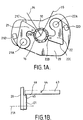
- a latch mechanism 10 including a body 11 which supports various components of the latch mechanism 10 as indicated below.
- Latch mechanism 10 further includes a claw 12 pivotally mounted about axis 13 on the body 11.
- Claw 12 acts to secure an associated door (not shown) in a closed position via a striker pin 14 attached to the door aperture. Rotation of the claw 12 in an anticlockwise direction about axis 13 when viewing Fig.1 allows release of the striker pin 14, thus enabling opening of the associated door.
- the claw 12 is held in a closed position by a pawl 15, only part of which is shown in dotted profile in Fig. for clarity.
- Pawl 15 is pivotally mounted on body 11 and can rotate about axis 16.
- Claw 12 can be held in a first safety position (not shown) when pawl 15 engages first safety abutment 17.
- Pawl lifter 20 is generally flat and lies in a plane parallel to pawl 15, to which it is rotationally secured. When viewing Fig.1 pawl 15 is obscured by pawl lifter 20. Clearly, pawl lifter 20 also rotates about axis 16.
- An output element in the form of an inside lock link 21 and a further output element in the form of outside lock link 22 are mounted for movement with the pawl, in this case they are each individually pivoted about respective axes 21a and 22a on pawl lifter 20.
- inside lock link 21 and outside lock link 22 are identical and each have respective north magnetic poles 21b and 22b and release abutments 21c and 22c.
- Magnetic field generator 30 is capable of rotating independently from pawl lifter 20 about axis 16. Magnetic field generator 30 has three sets of south magnetic poles S1, S2 and S3 and three sets of north magnetic poles N1,N2 and N3 shown diagrammatically in figure 1A for clarity. The magnetic field generator 30 further includes levers 34 and 35 shown schematically which are all rotationally fast with magnetic field generator 30. Preferably magnetic field generator 30 can at least be rotated to the various positions as described below by a power actuator (not shown) such as a DC motor or preferably a stepper motor.
- a power actuator such as a DC motor or preferably a stepper motor.
- Outside release lever 40 is pivotally mounted about axis 41 and is connected to an outside door handle.
- Inside release lever 43 (shown diagrammatically in Fig.1b) is pivotally mounted about axis 44 and is connected to an inside door handle.
- Fig.1 shows the door latch mechanism in a super lock condition, that is to say operation of the outside release lever 40 or inside release lever 43 does not allow unlatching of the mechanism.
- north magnetic pole 21b has being attracted to south magnetic pole set S2 and north magnetic pole 22b has being attracted towards south magnetic poles set S3.
- abutment 42 would pass release abutment 22c of outside lock link 22 without contact (note that outside release lever 40 is in the same plane as outside lock link 22).
- inside release lever 43 when operated by being rotated in an anticlockwise direction about axis 44 when viewing Fig.1b, would cause abutment 45 to pass release abutment 21c of inside lock link 21 (see especially Fig.1).
- Fig.2 shows the door latch mechanism 10 in a locked position with the child safety feature on.
- Magnetic field generator 30 has been rotated in an anticlockwise direction when compared to Fig.1.
- the inside lock link 21 and outside lock link 22 are in the same position when compared with Fig.1 since the north magnetic poles 21b and 22b are still attracted to respective south magnetic poles sets S2 and S3.
- lever 34 has been rotated to a position whereby operation of the inside release lever 43 in an anticlockwise direction when viewing Fig.1b would cause abutment 46 to contact lever 34 and rotate magnetic field generator 30 to the position shown in Fig.3.
- inside release lever 43 does not unlatch the mechanism but only operates to unlock the door (see below).
- This method of being able to override and open a locked door which has the child safety on is especially important in an emergency situation whereby a passer-by can effect access to the inside door handle (e.g. by breaking the door window glass), operate the inside door handle to unlock the door, then operate the outside door handle to open the door and then remove the child from the car.
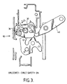
- Fig.3 shows the door latch mechanism 10 in an unlocked condition with the child safety feature on.
- the magnetic field generator has been rotated sufficiently (either by operating the inside release lever when the magnetic field generator was in the position shown in Fig.2 or by independent rotation of the magnetic field generator directly e.g. by a power actuator) such that north magnetic pole 21b is attracted towards the magnetic field generator but north magnetic pole 22b is repelled away from the magnetic field generator resulting in anticlockwise rotation of outside lock link 22.
- abutment 42 contacts release abutment 22c causing the pawl lifter 20 as a whole to rotate anticlockwise when viewing Fig.3 and releasing the pawl 15 and allowing the claw 12 to open.
- Stop 22d limits the anticlockwise rotation of outside lock link 22.
- the pawl lifter 20 Upon release of the outside release lever 40 the pawl lifter 20 is biased back to the position as shown in Fig.3 by a spring (not shown).
- the inside lock link 21 is in the same position as that shown in Fig.1, thus operation of the inside release lever 43 does not allow opening of the door.
- lock link 21 has remained in the same position as shown in figure 3 and figure 2 since the magnetic field in the region local to the magnetic pole 21b has remained unchanged.
- FIG. 3 shows that the magnetic field, as generated by the magnetic field generator, in the region of magnetic pole 22b is now a north pole. Thus, it is the change in magnetic field as generated by the magnetic field generator that causes the lock link 22 to move. Furthermore, for a change in magnetic field to have an effect on lock link 22, that change in magnetic field must, necessarily, be local to the lock link 22.
- Fig.4 shows the door latch mechanism 10 in a locked condition with the child safety feature off.
- the magnetic field generator 30 has been rotated in an anticlockwise direction when compared with Fig. 1. This results in north magnetic pole 22b being attracted towards the magnetic field generator and ensuring that operation of outside release lever 40 does not release the latch mechanism.
- the rotation of the magnetic field generator 30 has caused north magnetic pole 21b to be repelled from the magnetic field generator causing inside lock link 21 to rotate anticlockwise about axis 21 a.
- abutment 21c of inside lock link 21 is contacted by abutment 45 of inside release lever 43 when it is operated.
- Fig.5 shows the door latch mechanism 10 in an unlocked position with the child safety feature off. It can be seen that the magnetic field generator has been rotated (either by operating the inside release lever when the magnetic field generator was in the position shown in Fig.4 or by independent rotation of the magnetic field generator directly e.g. by a power actuator) such that north magnetic pole 22b is repelled away from the magnetic field generator 30 allowing operation of the outside release lever 40 to unlatch the latch mechanism as described above. Furthermore north magnetic pole 21b is repelled away from the magnetic field generator 30 thus ensuring that operation of the inside release lever also unlatches the door mechanism.
- Fig.6 shows the door latch mechanism 10 in a released position. This is achieved by rotation of magnetic field generator 30 in a anticlockwise direction which allows contact between corresponding lost motion abutments (not shown) on the pawl lifter 20 and magnetic field generator 30. Such lost motion abutments allow the magnetic field generator 30 to rotate the pawl lifter 20 to release the door latch mechanism independently of the operation of the outside release lever 40 or the inside release lever 43.
- the combination of the magnetic field generator 30 and inside lock link provides for an actuator according to the present invention. Furthermore the combination of the magnetic field generator 30 and the outside lock link provide for a further actuator according to the present invention. Thus in this particular case two actuators according to the present invention are provided having a common magnetic field generator.
- the inside lock lever forms part of the transmission path between the inside door handle and the pawl and the outside lock link forms part of the transmission path between the outside door handle and the pawl.
- locking of the latch mechanism is of the free wheeling type i.e. with the door in a locked condition operation of an outside door handle is possible but does not open the latch.
- an actuator according to the present invention may be provided which provides for block type locking i.e. the output element of the actuator prevents movement of say an outside door handle.
- inside and outside lock links can be mounted directly on the pawl.
- the magnetic field generator comprises an array of north and south magnetic poles and the output elements also include a magnetic pole (in this case a north magnetic pole).
- the array of magnetic poles on the magnetic field generator can be varied as can the polarity of the magnetic poles on the output element.
- the output elements need not include any magnetic poles but could consist of a material that is attracted to both a north and south magnetic pole of the magnetic field generator under these circumstances it would be possible to arrange for a resilient means to bias the output elements away from the magnetic field generator when a neutral magnetic field is generated in the vicinity of the output elements and when a magnetic field, either north or south is generated in the vicinity of the output element then that output element would be attracted towards the magnetic field generator.
- the magnetic field generator could be in the form of one or more electro-magnetics.
- one or more output elements could include an electromagnet arrangement.
- figure 7 shows, schematically, an actuator 108 having an electro magnetic 160, a moveable shield 162, and an output element 164 which is bias to the position as shown in figure 7 by spring 166.
- the output element 164 is bias to the position as shown in figure 7 by spring 166.
Landscapes
- Health & Medical Sciences (AREA)
- Child & Adolescent Psychology (AREA)
- Lock And Its Accessories (AREA)
- Gear-Shifting Mechanisms (AREA)
- Transmission Devices (AREA)
Abstract
Description
Claims (22)
- An actuator (8,108) including a device (160,162) for providing a magnetic field including a magnetic field generator (30,160), the actuator further including an output element (21, 22:164) being moveable between a first position where it blocks or breaks an associated mechanical transmission path and a second position where it unblocks or forms part of an associated mechanical transmission path, the output element being moveable as a result of changes in its local magnetic field as generated by the magnetic field generator, at least a part of the device being moveable to change said local magnetic field to effect movement of the output element.
- An actuator as defined in claim 1 in which said part of the device includes the magnetic field generator.
- An actuator as defined in claim 1 in which said device further includes a magnetic shield (162), the shield being moveable to change said local magnetic field.
- An actuator including a device for providing a magnetic field including a magnetic field generator (30) the actuator further including an output element (21,22) being moveable between a first position where it breaks an associated mechanical transmission path and a second position where it forms part of an associated mechanical transmission path, the output element being moveable as a result of changes in its local magnetic field as generated by the magnetic field generator, the device being operable to change said local magnetic field to effect movement of the output element, in which the actuator is caused to move during subsequent operation of an associated transmission path.
- An actuator as defined in any preceding claim in which the magnetic field generator is a permanent magnetic and/or an electromagnet.
- An actuator arrangement including an actuator according to any preceding claim, the actuator arrangement further including a mechanical transmission path.
- A latch mechanism (10) including an actuator arrangement as defined in claim 6 in which the latch mechanism includes a housing (11), a pawl (15) movably mounted in the housing to release the latch, the output element (21,22) forming an inside or outside lock link mounted for movement with the pawl in which with the output element in a first position, operation of an associated release means causes movement of the pawl to release the latch, and with the output element in the second position operation of the associated release means does not cause movement of the pawl.
- A latch mechanism as defined in claim 7 in which the pawl (15) is rotatably mounted in the housing (11).
- A latch mechanism as defined in claim 7 or 8 in which a pawl lifter (20) is connected to a pawl (15) and the lock link is mounted on the pawl lifter.
- A latch mechanism as defined in any one of claims 7 to 9 in which the lock link (21,22) is pivotally mounted for rotational movement between its first and second positions.
- A latch mechanism as defined in any one of claims 7 to 10 further including a further actuator arrangement according to claim 6 having a further output element forming another of an inside or outside lock link in which the inside and outside lock link are both mounted for movement with the pawl.
- A latch mechanism as defined in any one of claims 7 to 11 in which indexing of a the magnetic field generator (30) effects movement of the at least one lock link between its first and second positions.
- A latch mechanism as defined in claim 12 in which the magnetic field generator (30) is rotationally mounted for indexing.
- A latch mechanism as defined in claim 13 when dependent upon claim 8 in which the magnetic field generator is rotationally mounted co-axially with the pawl.
- A latch mechanism as defined in any one of claims 12 to 14 in which the magnetic field generator includes at least 2 discrete equivalent magnetic poles which position the at least one lock link in one of the first and second positions, with the at least 2 discrete equivalent magnetic poles being separated by an alternate magnetic pole which positions the at least one lock link in the other of the first and second positions.
- A latch mechanism as defined in any one of claims 11 to 15 in which the magnetic field generator (30) of the actuator is common with the magnetic field generator of the further actuator to effect movement of both the inside and outside lock links.
- A latch mechanism as defined in any one of claims 12 to 16 in which the release means is capable of indexing the magnetic field generator to move at least one of the lock links between the first and second positions.
- A latch mechanism as defined in claim 17 in which the release means is capable of indexing the magnetic field generator to move at least one of the lock links from its second position to its first position.
- A latch mechanism as defined in any one of claims 7 to 18 in which movement of the at least one lock link between its first and second position is effected by a power actuator.
- A latch mechanism as defined in any one of claims 7 to 19 in which the pawl is capable of being moved to release the latch by a power actuator.
- A latch mechanism as defined in claim 20 when dependent upon claim 19 in which the power actuator which indexes the magnetic field generator is the same power actuator which moves the pawl.
- A latch mechanism as defined in claim 21 in which the power actuator drives the magnetic field generator such that an abutment on the magnetic field generator operatively co-acts with an abutment fast with the pawl to release the latch mechanism.
Applications Claiming Priority (2)
| Application Number | Priority Date | Filing Date | Title |
|---|---|---|---|
| GB0018102 | 2000-07-25 | ||
| GBGB0018102.4A GB0018102D0 (en) | 2000-07-25 | 2000-07-25 | An actuator |
Publications (3)
| Publication Number | Publication Date |
|---|---|
| EP1176272A2 true EP1176272A2 (en) | 2002-01-30 |
| EP1176272A3 EP1176272A3 (en) | 2002-02-06 |
| EP1176272B1 EP1176272B1 (en) | 2007-08-29 |
Family
ID=9896212
Family Applications (1)
| Application Number | Title | Priority Date | Filing Date |
|---|---|---|---|
| EP01305985A Expired - Lifetime EP1176272B1 (en) | 2000-07-25 | 2001-07-11 | An actuator |
Country Status (4)
| Country | Link |
|---|---|
| US (1) | US6652009B2 (en) |
| EP (1) | EP1176272B1 (en) |
| DE (1) | DE60130174D1 (en) |
| GB (1) | GB0018102D0 (en) |
Cited By (1)
| Publication number | Priority date | Publication date | Assignee | Title |
|---|---|---|---|---|
| CN102199962B (en) * | 2005-02-23 | 2013-04-10 | 爱信精机株式会社 | Door lock apparatus |
Families Citing this family (9)
| Publication number | Priority date | Publication date | Assignee | Title |
|---|---|---|---|---|
| GB0105120D0 (en) * | 2001-03-02 | 2001-04-18 | Meritor Light Vehicle Sys Ltd | Mechanism |
| GB0121066D0 (en) * | 2001-08-31 | 2001-10-24 | Meritor Light Vehicle Sys Ltd | Door latch arrangement |
| US8918195B2 (en) * | 2003-01-02 | 2014-12-23 | Catch Media, Inc. | Media management and tracking |
| US7287785B2 (en) * | 2004-04-02 | 2007-10-30 | Intier Automotive Closures Inc. | Side door latch pawl function augmentation |
| RU2398948C2 (en) * | 2005-02-18 | 2010-09-10 | Меритор Текнолоджи, Инк. | Latch |
| US20070233185A1 (en) * | 2005-10-20 | 2007-10-04 | Thomas Anderson | Systems and methods for sealing a vascular opening |
| DE102007062080B4 (en) * | 2007-12-21 | 2012-09-27 | Hydac Electronic Gmbh | Device for activating a safety device, in particular an occupant protection device in a vehicle |
| US10641021B2 (en) | 2016-09-30 | 2020-05-05 | Barrette Outdoor Living, Inc. | Magnetic safety gate latch |
| US10662686B2 (en) | 2016-09-30 | 2020-05-26 | Barrette Outdoor Living, Inc. | Magnetic safety gate latch |
Family Cites Families (15)
| Publication number | Priority date | Publication date | Assignee | Title |
|---|---|---|---|---|
| US3976962A (en) | 1975-04-25 | 1976-08-24 | The United States Of America As Represented By The Secretary Of The Navy | Dual threshold magnetic proximity switch |
| FR2370350A1 (en) | 1976-11-05 | 1978-06-02 | Serras Paulet Edouard | ROTARY SWITCH, MOBILE MAGNETS |
| US4627251A (en) * | 1984-09-17 | 1986-12-09 | Bhate Suresh K | Combined mechanical and magnetic locking system |
| US4752092A (en) * | 1987-04-10 | 1988-06-21 | Abc Auto Alarms, Inc. | Remotely operated hood lock release blocker assembly for a vehicle |
| FR2614643B1 (en) * | 1987-04-29 | 1989-07-28 | Rockwell Cim | ASSEMBLY OF A DOOR LOCK AND AN ANTI-THEFT AND ANTI-AGGRESSION LOCKING DEVICE THEREOF AND LOCK PART OF THIS ASSEMBLY |
| US5088347A (en) * | 1987-12-09 | 1992-02-18 | Auto-Vation Inc. | Door lock actuator |
| DE3802107C1 (en) * | 1988-01-26 | 1989-05-03 | Daimler-Benz Aktiengesellschaft, 7000 Stuttgart, De | |
| DE3821840C1 (en) * | 1988-06-29 | 1989-10-19 | Heraeus Sepatech Gmbh, 3360 Osterode, De | |
| JPH0366882A (en) * | 1989-08-04 | 1991-03-22 | Shicoh Eng Co Ltd | Door locking device |
| GB9213652D0 (en) * | 1992-06-26 | 1992-08-12 | Sedley Bruce S | Magnetic locks |
| GB9314376D0 (en) | 1993-07-12 | 1993-08-25 | Chevalier John Phillip | Anti-theft locking system |
| DE19627246B4 (en) * | 1995-07-08 | 2005-10-13 | Kiekert Ag | Motor vehicle door lock, which is set up for the functional position "unlocked", "locked" and "additional secured" |
| GB9809640D0 (en) * | 1998-05-06 | 1998-07-01 | Meritor Light Vehicle Sys Ltd | Latch mechanism |
| US6027148A (en) * | 1998-06-12 | 2000-02-22 | Shoemaker; Rodney | Security device for a movable closure and method therefor |
| US5975596A (en) * | 1998-06-29 | 1999-11-02 | General Motors Corporation | Vehicle door latch |
-
2000
- 2000-07-25 GB GBGB0018102.4A patent/GB0018102D0/en not_active Ceased
-
2001
- 2001-07-11 DE DE60130174T patent/DE60130174D1/en not_active Expired - Lifetime
- 2001-07-11 EP EP01305985A patent/EP1176272B1/en not_active Expired - Lifetime
- 2001-07-24 US US09/911,920 patent/US6652009B2/en not_active Expired - Fee Related
Cited By (1)
| Publication number | Priority date | Publication date | Assignee | Title |
|---|---|---|---|---|
| CN102199962B (en) * | 2005-02-23 | 2013-04-10 | 爱信精机株式会社 | Door lock apparatus |
Also Published As
| Publication number | Publication date |
|---|---|
| EP1176272B1 (en) | 2007-08-29 |
| US6652009B2 (en) | 2003-11-25 |
| DE60130174D1 (en) | 2007-10-11 |
| US20020014775A1 (en) | 2002-02-07 |
| GB0018102D0 (en) | 2000-09-13 |
| EP1176272A3 (en) | 2002-02-06 |
Similar Documents
| Publication | Publication Date | Title |
|---|---|---|
| US7532098B2 (en) | Actuator | |
| US6099048A (en) | Automotive door latching system | |
| US6526790B2 (en) | Closing device | |
| US6371538B1 (en) | Vehicle door latch device with block type anti-theft mechanism | |
| US6045168A (en) | Door latch with improved double lock | |
| JP2019183492A (en) | Electric lock | |
| EP1176272B1 (en) | An actuator | |
| US6082158A (en) | Closing device | |
| EP1217155B1 (en) | Latch arrangement | |
| EP1355026A2 (en) | Latch arrangement | |
| EP1121503B8 (en) | Door latch | |
| CN114080484A (en) | motor vehicle door lock | |
| EP1084323B1 (en) | Latch mechanism | |
| EP1217153B1 (en) | Latch arrangement | |
| US11293205B2 (en) | Vehicle door lock device | |
| EP1212501A1 (en) | A powered vehicle door latch and actuator therefor | |
| EP1290301B1 (en) | Latch apparatus and method | |
| EP3029230B1 (en) | Relay mechanism of vehicle sliding door | |
| JP3661103B2 (en) | Electric lock emergency unlocking device | |
| US20030006618A1 (en) | Latch assembly and method of operating such an assembly | |
| GB2369404A (en) | Latch mechanism with alternate operating modes | |
| JP7707479B2 (en) | Vehicle door operating device | |
| JP2004244994A (en) | Door lock device | |
| JPH09228708A (en) | Door lock system | |
| JPH0548836B2 (en) |
Legal Events
| Date | Code | Title | Description |
|---|---|---|---|
| PUAI | Public reference made under article 153(3) epc to a published international application that has entered the european phase |
Free format text: ORIGINAL CODE: 0009012 |
|
| PUAL | Search report despatched |
Free format text: ORIGINAL CODE: 0009013 |
|
| AK | Designated contracting states |
Kind code of ref document: A2 Designated state(s): DE FR GB Kind code of ref document: A2 Designated state(s): AT BE CH CY DE DK ES FI FR GB GR IE IT LI LU MC NL PT SE TR |
|
| AX | Request for extension of the european patent |
Free format text: AL;LT;LV;MK;RO;SI |
|
| AK | Designated contracting states |
Kind code of ref document: A3 Designated state(s): AT BE CH CY DE DK ES FI FR GB GR IE IT LI LU MC NL PT SE TR |
|
| AX | Request for extension of the european patent |
Free format text: AL;LT;LV;MK;RO;SI |
|
| 17P | Request for examination filed |
Effective date: 20020516 |
|
| RAP1 | Party data changed (applicant data changed or rights of an application transferred) |
Owner name: ARVINMERITOR LIGHT VEHICLE SYSTEMS (UK) LTD |
|
| AKX | Designation fees paid |
Free format text: DE FR GB |
|
| 17Q | First examination report despatched |
Effective date: 20031219 |
|
| GRAP | Despatch of communication of intention to grant a patent |
Free format text: ORIGINAL CODE: EPIDOSNIGR1 |
|
| RAP1 | Party data changed (applicant data changed or rights of an application transferred) |
Owner name: MERITOR TECHNOLOGY, INC. |
|
| GRAS | Grant fee paid |
Free format text: ORIGINAL CODE: EPIDOSNIGR3 |
|
| GRAA | (expected) grant |
Free format text: ORIGINAL CODE: 0009210 |
|
| AK | Designated contracting states |
Kind code of ref document: B1 Designated state(s): DE FR GB |
|
| REG | Reference to a national code |
Ref country code: GB Ref legal event code: FG4D |
|
| REF | Corresponds to: |
Ref document number: 60130174 Country of ref document: DE Date of ref document: 20071011 Kind code of ref document: P |
|
| EN | Fr: translation not filed | ||
| PLBE | No opposition filed within time limit |
Free format text: ORIGINAL CODE: 0009261 |
|
| STAA | Information on the status of an ep patent application or granted ep patent |
Free format text: STATUS: NO OPPOSITION FILED WITHIN TIME LIMIT |
|
| PG25 | Lapsed in a contracting state [announced via postgrant information from national office to epo] |
Ref country code: DE Free format text: LAPSE BECAUSE OF FAILURE TO SUBMIT A TRANSLATION OF THE DESCRIPTION OR TO PAY THE FEE WITHIN THE PRESCRIBED TIME-LIMIT Effective date: 20071130 |
|
| 26N | No opposition filed |
Effective date: 20080530 |
|
| PGFP | Annual fee paid to national office [announced via postgrant information from national office to epo] |
Ref country code: GB Payment date: 20100707 Year of fee payment: 10 |
|
| REG | Reference to a national code |
Ref country code: GB Ref legal event code: 732E Free format text: REGISTERED BETWEEN 20101230 AND 20110105 |
|
| GBPC | Gb: european patent ceased through non-payment of renewal fee |
Effective date: 20110711 |
|
| PG25 | Lapsed in a contracting state [announced via postgrant information from national office to epo] |
Ref country code: GB Free format text: LAPSE BECAUSE OF NON-PAYMENT OF DUE FEES Effective date: 20110711 |
|
| PG25 | Lapsed in a contracting state [announced via postgrant information from national office to epo] |
Ref country code: FR Free format text: LAPSE BECAUSE OF FAILURE TO SUBMIT A TRANSLATION OF THE DESCRIPTION OR TO PAY THE FEE WITHIN THE PRESCRIBED TIME-LIMIT Effective date: 20080425 |