EP1176292A1 - Vorrichtung zur Abgasreinigung für eine Brennkraftmaschine - Google Patents
Vorrichtung zur Abgasreinigung für eine Brennkraftmaschine Download PDFInfo
- Publication number
- EP1176292A1 EP1176292A1 EP01117847A EP01117847A EP1176292A1 EP 1176292 A1 EP1176292 A1 EP 1176292A1 EP 01117847 A EP01117847 A EP 01117847A EP 01117847 A EP01117847 A EP 01117847A EP 1176292 A1 EP1176292 A1 EP 1176292A1
- Authority
- EP
- European Patent Office
- Prior art keywords
- reducing
- agent
- pressure
- valve
- exhaust gas
- Prior art date
- Legal status (The legal status is an assumption and is not a legal conclusion. Google has not performed a legal analysis and makes no representation as to the accuracy of the status listed.)
- Granted
Links
Images








Classifications
-
- F—MECHANICAL ENGINEERING; LIGHTING; HEATING; WEAPONS; BLASTING
- F02—COMBUSTION ENGINES; HOT-GAS OR COMBUSTION-PRODUCT ENGINE PLANTS
- F02D—CONTROLLING COMBUSTION ENGINES
- F02D9/00—Controlling engines by throttling air or fuel-and-air induction conduits or exhaust conduits
- F02D9/04—Controlling engines by throttling air or fuel-and-air induction conduits or exhaust conduits concerning exhaust conduits
-
- F—MECHANICAL ENGINEERING; LIGHTING; HEATING; WEAPONS; BLASTING
- F01—MACHINES OR ENGINES IN GENERAL; ENGINE PLANTS IN GENERAL; STEAM ENGINES
- F01N—GAS-FLOW SILENCERS OR EXHAUST APPARATUS FOR MACHINES OR ENGINES IN GENERAL; GAS-FLOW SILENCERS OR EXHAUST APPARATUS FOR INTERNAL-COMBUSTION ENGINES
- F01N3/00—Exhaust or silencing apparatus having means for purifying, rendering innocuous, or otherwise treating exhaust
- F01N3/08—Exhaust or silencing apparatus having means for purifying, rendering innocuous, or otherwise treating exhaust for rendering innocuous
-
- F—MECHANICAL ENGINEERING; LIGHTING; HEATING; WEAPONS; BLASTING
- F01—MACHINES OR ENGINES IN GENERAL; ENGINE PLANTS IN GENERAL; STEAM ENGINES
- F01N—GAS-FLOW SILENCERS OR EXHAUST APPARATUS FOR MACHINES OR ENGINES IN GENERAL; GAS-FLOW SILENCERS OR EXHAUST APPARATUS FOR INTERNAL-COMBUSTION ENGINES
- F01N11/00—Monitoring or diagnostic devices for exhaust-gas treatment apparatus
-
- F—MECHANICAL ENGINEERING; LIGHTING; HEATING; WEAPONS; BLASTING
- F01—MACHINES OR ENGINES IN GENERAL; ENGINE PLANTS IN GENERAL; STEAM ENGINES
- F01N—GAS-FLOW SILENCERS OR EXHAUST APPARATUS FOR MACHINES OR ENGINES IN GENERAL; GAS-FLOW SILENCERS OR EXHAUST APPARATUS FOR INTERNAL-COMBUSTION ENGINES
- F01N3/00—Exhaust or silencing apparatus having means for purifying, rendering innocuous, or otherwise treating exhaust
- F01N3/08—Exhaust or silencing apparatus having means for purifying, rendering innocuous, or otherwise treating exhaust for rendering innocuous
- F01N3/0807—Exhaust or silencing apparatus having means for purifying, rendering innocuous, or otherwise treating exhaust for rendering innocuous by using absorbents or adsorbents
- F01N3/0828—Exhaust or silencing apparatus having means for purifying, rendering innocuous, or otherwise treating exhaust for rendering innocuous by using absorbents or adsorbents characterised by the absorbed or adsorbed substances
- F01N3/0842—Nitrogen oxides
-
- F—MECHANICAL ENGINEERING; LIGHTING; HEATING; WEAPONS; BLASTING
- F01—MACHINES OR ENGINES IN GENERAL; ENGINE PLANTS IN GENERAL; STEAM ENGINES
- F01N—GAS-FLOW SILENCERS OR EXHAUST APPARATUS FOR MACHINES OR ENGINES IN GENERAL; GAS-FLOW SILENCERS OR EXHAUST APPARATUS FOR INTERNAL-COMBUSTION ENGINES
- F01N3/00—Exhaust or silencing apparatus having means for purifying, rendering innocuous, or otherwise treating exhaust
- F01N3/08—Exhaust or silencing apparatus having means for purifying, rendering innocuous, or otherwise treating exhaust for rendering innocuous
- F01N3/0807—Exhaust or silencing apparatus having means for purifying, rendering innocuous, or otherwise treating exhaust for rendering innocuous by using absorbents or adsorbents
- F01N3/0871—Exhaust or silencing apparatus having means for purifying, rendering innocuous, or otherwise treating exhaust for rendering innocuous by using absorbents or adsorbents using means for controlling, e.g. purging, the absorbents or adsorbents
-
- F—MECHANICAL ENGINEERING; LIGHTING; HEATING; WEAPONS; BLASTING
- F02—COMBUSTION ENGINES; HOT-GAS OR COMBUSTION-PRODUCT ENGINE PLANTS
- F02M—SUPPLYING COMBUSTION ENGINES IN GENERAL WITH COMBUSTIBLE MIXTURES OR CONSTITUENTS THEREOF
- F02M26/00—Engine-pertinent apparatus for adding exhaust gases to combustion-air, main fuel or fuel-air mixture, e.g. by exhaust gas recirculation [EGR] systems
- F02M26/13—Arrangement or layout of EGR passages, e.g. in relation to specific engine parts or for incorporation of accessories
- F02M26/22—Arrangement or layout of EGR passages, e.g. in relation to specific engine parts or for incorporation of accessories with coolers in the recirculation passage
- F02M26/23—Layout, e.g. schematics
-
- F—MECHANICAL ENGINEERING; LIGHTING; HEATING; WEAPONS; BLASTING
- F02—COMBUSTION ENGINES; HOT-GAS OR COMBUSTION-PRODUCT ENGINE PLANTS
- F02M—SUPPLYING COMBUSTION ENGINES IN GENERAL WITH COMBUSTIBLE MIXTURES OR CONSTITUENTS THEREOF
- F02M26/00—Engine-pertinent apparatus for adding exhaust gases to combustion-air, main fuel or fuel-air mixture, e.g. by exhaust gas recirculation [EGR] systems
- F02M26/13—Arrangement or layout of EGR passages, e.g. in relation to specific engine parts or for incorporation of accessories
- F02M26/22—Arrangement or layout of EGR passages, e.g. in relation to specific engine parts or for incorporation of accessories with coolers in the recirculation passage
- F02M26/33—Arrangement or layout of EGR passages, e.g. in relation to specific engine parts or for incorporation of accessories with coolers in the recirculation passage controlling the temperature of the recirculated gases
-
- F—MECHANICAL ENGINEERING; LIGHTING; HEATING; WEAPONS; BLASTING
- F01—MACHINES OR ENGINES IN GENERAL; ENGINE PLANTS IN GENERAL; STEAM ENGINES
- F01N—GAS-FLOW SILENCERS OR EXHAUST APPARATUS FOR MACHINES OR ENGINES IN GENERAL; GAS-FLOW SILENCERS OR EXHAUST APPARATUS FOR INTERNAL-COMBUSTION ENGINES
- F01N2240/00—Combination or association of two or more different exhaust treating devices, or of at least one such device with an auxiliary device, not covered by indexing codes F01N2230/00 or F01N2250/00, one of the devices being
- F01N2240/36—Combination or association of two or more different exhaust treating devices, or of at least one such device with an auxiliary device, not covered by indexing codes F01N2230/00 or F01N2250/00, one of the devices being an exhaust flap
-
- F—MECHANICAL ENGINEERING; LIGHTING; HEATING; WEAPONS; BLASTING
- F01—MACHINES OR ENGINES IN GENERAL; ENGINE PLANTS IN GENERAL; STEAM ENGINES
- F01N—GAS-FLOW SILENCERS OR EXHAUST APPARATUS FOR MACHINES OR ENGINES IN GENERAL; GAS-FLOW SILENCERS OR EXHAUST APPARATUS FOR INTERNAL-COMBUSTION ENGINES
- F01N2260/00—Exhaust treating devices having provisions not otherwise provided for
- F01N2260/14—Exhaust treating devices having provisions not otherwise provided for for modifying or adapting flow area or back-pressure
-
- F—MECHANICAL ENGINEERING; LIGHTING; HEATING; WEAPONS; BLASTING
- F01—MACHINES OR ENGINES IN GENERAL; ENGINE PLANTS IN GENERAL; STEAM ENGINES
- F01N—GAS-FLOW SILENCERS OR EXHAUST APPARATUS FOR MACHINES OR ENGINES IN GENERAL; GAS-FLOW SILENCERS OR EXHAUST APPARATUS FOR INTERNAL-COMBUSTION ENGINES
- F01N2550/00—Monitoring or diagnosing the deterioration of exhaust systems
- F01N2550/05—Systems for adding substances into exhaust
-
- F—MECHANICAL ENGINEERING; LIGHTING; HEATING; WEAPONS; BLASTING
- F01—MACHINES OR ENGINES IN GENERAL; ENGINE PLANTS IN GENERAL; STEAM ENGINES
- F01N—GAS-FLOW SILENCERS OR EXHAUST APPARATUS FOR MACHINES OR ENGINES IN GENERAL; GAS-FLOW SILENCERS OR EXHAUST APPARATUS FOR INTERNAL-COMBUSTION ENGINES
- F01N2610/00—Adding substances to exhaust gases
- F01N2610/03—Adding substances to exhaust gases the substance being hydrocarbons, e.g. engine fuel
-
- F—MECHANICAL ENGINEERING; LIGHTING; HEATING; WEAPONS; BLASTING
- F01—MACHINES OR ENGINES IN GENERAL; ENGINE PLANTS IN GENERAL; STEAM ENGINES
- F01N—GAS-FLOW SILENCERS OR EXHAUST APPARATUS FOR MACHINES OR ENGINES IN GENERAL; GAS-FLOW SILENCERS OR EXHAUST APPARATUS FOR INTERNAL-COMBUSTION ENGINES
- F01N2610/00—Adding substances to exhaust gases
- F01N2610/14—Arrangements for the supply of substances, e.g. conduits
- F01N2610/1493—Purging the reducing agent out of the conduits or nozzle
-
- F—MECHANICAL ENGINEERING; LIGHTING; HEATING; WEAPONS; BLASTING
- F02—COMBUSTION ENGINES; HOT-GAS OR COMBUSTION-PRODUCT ENGINE PLANTS
- F02B—INTERNAL-COMBUSTION PISTON ENGINES; COMBUSTION ENGINES IN GENERAL
- F02B37/00—Engines characterised by provision of pumps driven at least for part of the time by exhaust
-
- F—MECHANICAL ENGINEERING; LIGHTING; HEATING; WEAPONS; BLASTING
- F02—COMBUSTION ENGINES; HOT-GAS OR COMBUSTION-PRODUCT ENGINE PLANTS
- F02M—SUPPLYING COMBUSTION ENGINES IN GENERAL WITH COMBUSTIBLE MIXTURES OR CONSTITUENTS THEREOF
- F02M26/00—Engine-pertinent apparatus for adding exhaust gases to combustion-air, main fuel or fuel-air mixture, e.g. by exhaust gas recirculation [EGR] systems
- F02M26/02—EGR systems specially adapted for supercharged engines
- F02M26/04—EGR systems specially adapted for supercharged engines with a single turbocharger
- F02M26/05—High pressure loops, i.e. wherein recirculated exhaust gas is taken out from the exhaust system upstream of the turbine and reintroduced into the intake system downstream of the compressor
-
- F—MECHANICAL ENGINEERING; LIGHTING; HEATING; WEAPONS; BLASTING
- F02—COMBUSTION ENGINES; HOT-GAS OR COMBUSTION-PRODUCT ENGINE PLANTS
- F02M—SUPPLYING COMBUSTION ENGINES IN GENERAL WITH COMBUSTIBLE MIXTURES OR CONSTITUENTS THEREOF
- F02M26/00—Engine-pertinent apparatus for adding exhaust gases to combustion-air, main fuel or fuel-air mixture, e.g. by exhaust gas recirculation [EGR] systems
- F02M26/02—EGR systems specially adapted for supercharged engines
- F02M26/09—Constructional details, e.g. structural combinations of EGR systems and supercharger systems; Arrangement of the EGR and supercharger systems with respect to the engine
- F02M26/10—Constructional details, e.g. structural combinations of EGR systems and supercharger systems; Arrangement of the EGR and supercharger systems with respect to the engine having means to increase the pressure difference between the exhaust and intake system, e.g. venturis, variable geometry turbines, check valves using pressure pulsations or throttles in the air intake or exhaust system
-
- Y—GENERAL TAGGING OF NEW TECHNOLOGICAL DEVELOPMENTS; GENERAL TAGGING OF CROSS-SECTIONAL TECHNOLOGIES SPANNING OVER SEVERAL SECTIONS OF THE IPC; TECHNICAL SUBJECTS COVERED BY FORMER USPC CROSS-REFERENCE ART COLLECTIONS [XRACs] AND DIGESTS
- Y02—TECHNOLOGIES OR APPLICATIONS FOR MITIGATION OR ADAPTATION AGAINST CLIMATE CHANGE
- Y02T—CLIMATE CHANGE MITIGATION TECHNOLOGIES RELATED TO TRANSPORTATION
- Y02T10/00—Road transport of goods or passengers
- Y02T10/10—Internal combustion engine [ICE] based vehicles
- Y02T10/40—Engine management systems
Definitions
- the present invention relates to an exhaust gas purifying apparatus for purifying nitrogen oxides (NOx) included in exhaust gas by an exhaust gas purifying catalyst arranged on an exhaust passage of an internal combustion engine.
- NOx nitrogen oxides
- a lean NOx catalyst such as a selective reduction NOx catalyst or storage-reduction NOx catalyst at an exhaust passage of an internal combustion engine.
- the selective reduction NOx catalyst is a catalyst for reducing or decomposing nitrogen oxides (NOx) when hydrocarbons (HC) are present in an oxygen excessive atmosphere.
- the storage-reduction NOx catalyst is a catalyst storing nitrogen oxides (NOx) in exhaust gas when an air/fuel ratio of exhaust gas flowing to the storage-reduction NOx catalyst is the lean air/fuel ratio and discharging and reducing the stored nitrogen oxides (NOx) when an oxygen concentration of exhaust gas flowing to the storage-reduction NOx catalyst is reduced and a reducing-agent is present.
- NOx nitrogen oxides
- NOx nitrogen oxides
- an exhaust passage branched to a first exhaust passage and a second exhaust passage at its midway, a first catalytic converter provided at the first exhaust passage for containing an storage-reduction NOx catalyst, a second catalytic converter provided at the second exhaust passage for containing a selective reduction NOx catalyst, a switch valve provided at a branch portion of a first exhaust pipe and a second exhaust pipe for shutting off the first exhaust passage when temperature of exhaust gas is changed from high temperature to low temperature and shutting off the second exhaust passage when the temperature of exhaust gas is changed from low temperature to high temperature and a reducing-agent supplying means for supplying reducing-agent to the first catalytic converter.
- the switch valve is controlled such that the exhaust gas flows in the second exhaust gas passage and the internal combustion engine is controlled to carry out fuel injection secondarily in an expansion stroke or in an exhaust stroke and when the NOx purifying rate of the storage-reduction NOx catalyst becomes higher than that of the selective reduction NOx catalyst as in changing the temperature of exhaust gas from high temperature to low temperature, the switch valve is controlled such that the exhaust gas flows in the first exhaust gas passage, the reducing-agent adding means is controlled such that the reducing-agent is added to the storage-reduction NOx catalyst, thereby, the selective reduction NOx catalyst and the storage-reduction NOx catalyst are separately used in accordance with characteristics of the respective to thereby promote the purifying rate of nitrogen oxides (NOx).
- NOx nitrogen oxides
- the reducing-agent supplying means there is disclosed a mechanism having an injection nozzle attached to the first catalytic converter, a reducing-agent pipe for conducting a portion of fuel to the injection nozzle from an accumulating chamber for accumulating fuel discharged from a fuel pump and distributing the fuel to fuel injection valves and a reducing-agent valve provided at a midway of the reducing-agent pipe for regulating a flow rate of fuel flowing in the reducing-agent pipe.
- the present invention has been carried out in view of the above-described various situations and it is an object thereof to prevent deterioration or damage of the lean NOx catalyst, or deterioration of the exhaust gas caused by leakage of reducing-agent by providing a technology capable of detecting leakage of the reducing-agent at a reducing-agent supplying apparatus for supplying the reducing-agent to the lean NOx catalyst provided at an exhaust passage of an internal combustion engine.
- the reducing-agent supplying mechanism is controlled to supply the reducing-agent to the lean NOx catalyst, there is conceivable a method of determining the reducing-agent supplying mechanism as normal when the air/fuel ratio of exhaust gas is changed in accordance with supply of the reducing-agent and determining the reducing-agent supplying mechanism as abnormal when the air/fuel ratio of exhaust gas is not changed in accordance with supply of the reducing-agent.
- the present invention adopts followings means in order to resolve the above-described problem.
- an exhaust gas purifying apparatus of an internal combustion engine characterized in comprising:
- the reducing-agent supplying mechanism supplies the reducing-agent to the exhaust passage upstream from the exhaust gas purifying catalyst.
- the reducing-agent supplied to the exhaust gas flows into the exhaust gas purifying catalyst along with exhaust gas flowing from the upstream side of the exhaust passage.
- the exhaust gas purifying catalyst reduces and purify the harmful gas components in the exhaust gas by utilizing the reducing-agent.
- pressure detecting means detects the pressure of the reducing-agent in the reducing-agent supplying mechanism. At this occasion, when the reducing-agent is leaked in the reducing-agent supplying mechanism, the pressure detected by the pressure detecting means becomes a value different from the pressure when the reducing-agent is not leaked in the reducing-agent supplying mechanism.
- the abnormality determining means can determine the abnormality of the reducing-agent supplying mechanism on the basis of the pressure detected by the pressure detecting means.
- the abnormality determining means may determine that the reducing-agent supplying mechanism is abnormal when the pressure detected by the pressure detecting means is deviated froma predetermined range, more specifically, when the pressure detected by the pressure detecting means is below a predetermined lower limit value.
- the reducing-agent supplying mechanism comprising:
- the reducing-agent supplying mechanism comprising:
- the abnormality determining means determines abnormality of the reducing-agent supplying mechanism on the basis of the pressure of the closed space.
- the pressure in the closed space is lowered, when the reducing-agent is leaked from outside of the closed space into the closed space, that is, when leakage of the reducing-agent is caused in the shut-off unit, the pressure in the closed space is elevated.
- the abnormality determining means can determine leakage of the reducing-agent in the reducing-agent supplying mechanism by lowering or elevating the pressure in the closed space.
- the abnormality determining means may determine that the reducing-agent supplying mechanism is abnormal.
- the shut-off unit shuts off flow of the reducing-agent from the reducing-agent discharging unit to the reducing-agent supplying passage to thereby form a closed space
- the pressure detecting means detects that the pressure of the closed space when operation of the internal combustion is stopped and detects again the pressure of the closed space when the internal combustion engine is started again
- the abnormality determining means calculates an amount of change of the pressure of the closed space during a period from when the operation of the internal combustion engine has been stopped until the internal combustion engine is started again and determines that the reducing-agent supplying mechanism is abnormal when the pressure change amount exceeds a predetermined amount.
- leakage of the reducing-agent is determined on the basis of the change of the pressure of the closed space during the comparatively long period from when operation of the internal combustion engine has been stopped until the internal combustion engine is started again and therefore, leakage of a small amount of the reducing-agent becomes easy to detect.
- the internal combustion engine there can be exemplified a lean burn type internal combustion engine such as a lean burn gasoline engine of a direct injection type or a diesel engine of a direct injection type.
- the exhaust gas purifying catalyst there can be exemplified an storage-reduction NOx catalyst or a selective reduction NOx catalyst.
- a reducing-agent including hydrocarbons (HC) such as gas oil or gasoline.
- HC hydrocarbons
- the reducing-agent discharging unit of the reducing-agent supplying mechanism there can be exemplified a fuel pump with running torque of an output shaft (crankshaft) of an internal combustion engine as a drive source.
- an apparatus comprising:
- the pressure detecting means is provided downstream from the passage opening and closing means in the reducing-agent supplying passage for detecting the pressure of the reducing-agent in the reducing-agent supplying passage, and the abnormality determining means determines the abnormality on the basis of the pressure detected by the pressure detecting means during a valve opening period and before and after the valve opening period of said passage opening and closing valve.
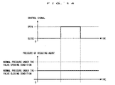
- the exhaust gas purifying apparatus of an internal combustion engine constituted in this way, when the passage opening/closing valve is opened, the reducing-agent supplying passage from the reducing-agent discharging unit to the reducing-agent adding unit, is brought into a conductive state and therefore, the reducing-agent discharged from the reducing-agent discharging unit is supplied to the reducing-agent adding unit and pressure of the reducing-agent applied to the reducing-agent adding unit is elevated.
- the pressure of the reducing-agent applied to the reducing-agent adding unit is elevated to be equal to or higher than the valve opening pressure, the reducing-agent adding unit is opened and the reducing-agent is added into the exhaust passage.
- the reducing-agent added from the reducing-agent adding unit into the exhaust passage flows into the exhaust gas purifying catalyst while being mixed with exhaust gas flowing from the upstream side of the exhaust passage.
- exhaust gas flowing into the exhaust gas purifying catalyst becomes exhaust gas having a low oxygen concentration and a high concentration of the reducing-agent and therefore, the exhaust gas purifying catalyst can purify harmful gas components in exhaust gas.
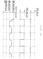
- the reducing-agent continues to be supplied from the reducing-agent discharging unit to the reducing-agent adding unit and therefore, pressure downstream from the passage opening/closing valve in the reducing-agent supplying passage, becomes equal to or higher than the valve opening pressure of the reducing-agent adding unit.
- the reducing-agent supplying passage disposed between the passage opening/closing valve and the reducing-agent adding unit becomes a closed space and therefore, pressure of the reducing-agent in the reducing-agent supplying passage downstream from the passage opening/closing valve, is stabilized at pressure that is lower than the valve opening pressure of the reducing-agent adding unit.
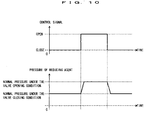
- the abnormality determining means determines abnormality on the basis of pressure detected by the pressure detecting means. Specifically, the abnormality determining means determines abnormality of the reducing-agent adding unit and/or the passage opening/closing valve on the basis of pressure detected by the pressure detecting means during the valve opening period of the passage opening/closing valve, pressure detected by the pressure detecting means before the valve opening period and pressure detected by the pressure detecting means after the valve opening period.
- first pressure the valve opening pressure of the reducing-agent adding unit
- the pressure downstream from the passage opening/closing valve in the reducing-agent supplying passage becomes pressure equal to or higher than the valve opening pressure of the adding nozzle (hereinafter, referred to as second pressure).
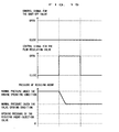
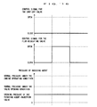
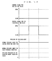
- pressure detected by the pressure detecting means before the valve opening period of the passage opening/closing valve becomes the first pressure
- pressure detected by the pressure detecting means during the valve opening period becomes the second pressure
- pressure detected by the pressure detecting means after the valve opening period becomes the first pressure
- the reducing-agent adding unit when the reducing-agent adding unit is brought into a failure in closing, the reducing-agent adding unit is always opened and therefore, before the valve opening period of the passage opening/closing valve and after the valve opening period, the pressure downstream from the passage opening/closing valve becomes lower than the first pressure.
- the passage opening/closing valve when the passage opening/closing valve is brought into a failure in opening the valve, the passage opening/closing valve is always closed and therefore, the pressure downstream from the passage opening/closing valve becomes constant during the valve opening period and before and after the valve opening period and becomes pressure lower than the second pressure.
- the passage opening/closing valve when the passage opening/closing valve is brought into a failure in closing the valve, the passage opening/closing valve is always opened, the reducing-agent is supplied always from the reducing-agent discharging unit to the reducing-agent adding unit and therefore, pressure of the reducing-agent applied to the reducing-agent adding unit becomes always equal to or higher than the valve opening pressure.
- the reducing-agent adding unit is also brought into an always opening state, the pressure downstream from the passage opening/closing valve becomes constant during the valve opening period and before and after the valve opening period and becomes pressure higher than the first pressure.
- the abnormality determining means can determine abnormality of the reducing-agent adding unit and/or the passage opening/closing valve on the basis of pressure detected by the pressure detecting means during, before or after the valve opening period of the passage opening/closing valve.
- the reducing-agent supplying mechanism can be constituted by an apparatus comprising:
- the pressure detecting means is provided between the amount controlling valve and the shut-off valve in the reducing-agent supplying passage for detecting the pressure of the reducing-agent in the reducing-agent supplying passage
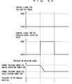
- the abnormality determining means determines the abnormality of the shut-off valve or the amount controlling valve or the reducing-agent adding unit on the basis of a detected value of the pressure detecting means after the amount controlling valve and the shut-off valve are controlled to close and a detected value of the pressure detecting means after the amount controlling valve is controlled to open thereafter and controlled to close.
- the shut-off valve and the amount controlling valve are controlled to open.
- the shut-off valve and the amount controlling valve are opened, the reducing-agent supplying passage from the reducing-agent discharging unit to the reducing-agent adding unit is brought into a conductive state and the reducing-agent discharged from the reducing-agent discharging unit is applied to the reducing-agent adding unit.
- pressure of the reducing-agent applied to the reducing-agent adding unit becomes higher than the valve opening pressure of the reducing-agent adding unit, the reducing-agent adding unit is opened and the reducing-agent is injected into the exhaust passage.
- the reducing-agent injected into the exhaust passage flows into the exhaust gas purifying catalyst while being mixed with exhaust gas flowing from the upstream side of the exhaust passage and reduces and purify harmful gas components in exhaust gas. Thereafter, when the amount controlling valve is closed, supply of the reducing-agent from the reducing-agent discharging unit to the reducing-agent adding unit is shut off and therefore, pressure of the reducing-agent applied to the reducing-agent adding unit is gradually lowered. When pressure of the reducing-agent applied to the reducing-agent adding unit becomes equal to or lower than the valve opening pressure, the reducing-agent adding unit is closed and injection of the reducing-agent into the exhaust passage is stopped.
- the abnormality determining means determines abnormality of the reducing-agent adding unit, the amount controlling valve and the shut-off valve on the basis of detected values of the pressure detecting means in respective states in which the amount controlling valve is brought into the valve closing state and in which the shut-off valve is controlled to close and thereafter, the amount controlling valve is controlled to open and close.
- the reducing-agent supply passage from the shut-off valve to the reducing-agent adding unit is partitioned into two spaces with the amount controlling valve as a boundary.
- pressure of the reducing-agent in the space upstream from the amount controlling valve becomes pressure substantially equal to pressure of the reducing-agent applied when the reducing-agent discharging unit discharges the reducing-agent (hereinafter, referred to as "reducing-agent discharging unit operating time pressure").
- the reducing-agent adding unit is opened at predetermined pressure and pressure of the reducing-agent is lowered and therefore, pressure of the reducing-agent becomes pressure substantially equal to the valve opening pressure of the reducing-agent adding unit.
- the shut-off valve when the shut-off valve is controlled to close, the reducing-agent supply passage from the amount controlling valve to the shut-off valve becomes a space closed by the amount controlling valve and the shut-off valve.
- the reducing-agent when the reducing-agent is not leaked or there is no abnormality in opening and closing the valves, pressure remains unchanged.
- the amount controlling valve when the amount controlling valve is controlled to open, the space stored with the reducing-agent at the reducing-agent discharging unit operating time pressure and the space stored with the reducing-agent at the valve opening pressure of the reducing-agent adding unit, are communicated with each other.
- pressure of the reducing-agent in the reducing-agent supply passage from the shut-off valve to the reducing-agent adding unit after the amount controlling valve has been controlled to open is gradually lowered with addition of the reducing-agent from the reducing-agent adding unit.
- pressure provided from the pressure detecting means at this occasion is equal to the reducing-agent discharging unit operating time pressure
- addition of the reducing-agent from the reducing-agent adding unit is not carried out. Therefore, pressure of the reducing-agent is not lowered.
- the reducing-agent adding unit is clogged or brought into an operational failure in the valve closing state.
- the reducing-agent discharging unit discharges the reducing-agent through inertia just after stopping the vehicle and a discharging amount is gradually lowered with elapse of time.
- the amount controlling valve is controlled to open and controlled to close as described above by a plurality of times, pressure of the reducing-agent in the reducing-agent supplying passage from the shut-off valve to the amount controlling valve, is gradually lowered.
- pressure detected by the pressure detecting means by remaining pressure from the reducing-agent discharging unit is not lowered. In this way, there can be determined the case in which the shut-off valve is brought into the operational failure in the valve opening state.
- the abnormality determining means can detect abnormality of the amount controlling valve, the shut-off valve or the reducing-agent adding unit and can specify an abnormal portion and specify cause of abnormality to some degree on the basis of the detected value of the pressure detecting means.
- the reducing-agent supplying mechanism can be constructed by a constitution comprising:
- the pressure detecting means is provided between the reducing-agent adding unit and the shut-off valve in the reducing-agent supplying passage for detecting the pressure of the reducing-agent in the reducing-agent supplying passage
- the abnormality determining means determines the abnormality of the shut-off valve or the reducing-agent adding unit on the basis of a detected value of the pressure detecting means after the reducing-agent adding unit and the shut-off valve have been controlled to close and a detected value of the pressure detecting means after the reducing-agent adding unit is controlled to open and controlled to close thereafter.
- the shut-off valve and the reducing-agent adding unit are controlled to open.
- the shut-off valve and the reducing-agent adding unit are opened, the reducing-agent supplying passage from the reducing-agent discharging unit to the reducing-agent adding unit is brought into a conductive state and the reducing-agent is injected into the exhaust passage.
- the reducing-agent injected into the exhaust passage flows into the exhaust gas purifying catalyst while being mixed with exhaust gas flowing from the upstream side of the exhaust passage and reduce and purify harmful gas components in exhaust gas. Thereafter, when the reducing-agent adding unit is closed, supply of the reducing-agent from the reducing-agent discharging unit is shut off and injection of the reducing-agent into the exhaust passage is stopped.
- the abnormality determining means determines abnormality of the reducing-agent adding unit or the shut-off valve on the basis ofdetected values of the pressure detecting means in respective states in which the shut-off valve is controlled to close when the reducing-agent adding unit is brought into the valve closing state and in which the reducing-agent adding unit is controlled to open and close thereafter.
- reducing-agent discharging unit operating time pressure when leakage of the reducing-agent is not caused upstream from the reducing-agent adding unit, pressure of the reducing-agent in the reducing-agent supply passage upstream from the reducing-agent adding unit, becomes pressure substantially equal to pressure of the reducing-agent applied when the reducing-agent discharging unit discharges the reducing-agent (hereinafter, referred to as "reducing-agent discharging unit operating time pressure").
- the shut-off valve when the shut-off valve is controlled to close, the reducing-agent supply passage from the reducing-agent adding unit to the shut-off valve becomes a close space by the shut-off valve and the reducing-agent adding unit.
- the reducing-agent when the reducing-agent is not leaked or there is no abnormality in opening and closing the valves, pressure remains unchanged.
- the reducing-agent adding unit when the reducing-agent adding unit is controlled to open, pressure of the reducing-agent from the shut-off valve to the reducing-agent adding unit, is gradually lowered with addition of the reducing-agent from the reducing-agent adding unit.
- the reducing-agent discharging unit discharges the reducing-agent through inertia just after stopping the vehicle, the discharging amount is gradually lowered with elapse of time.
- the reducing-agent adding unit is controlled to open and controlled to close as described above by a plurality of times, pressure of the reducing-agent in the reducing-agent supplying passage from the shut-off valve to the reducing-agent adding unit is gradually lowered.
- pressure detected by the pressure detecting means is not lowered by remaining pressure from the reducing-agent discharging unit.
- the abnormality determining means can detect abnormality of the shut-off valve or the reducing-agent adding unit and can specify an abnormal portion and specify cause of abnormality to some degree.
- a timing at which the detected value of the pressure detecting means becomes the predetermined pressure in other words, a timing at which pressure of the reducing-agent in the reducing-agent supplying passage disposed between the shut-off valve and the amount controlling valve, becomes the predetermined pressure, there can be exemplified a timing immediately after the reducing-agent discharging unit stop operating.
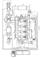
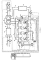
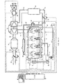
- Fig. 1 is a view showing a schematic constitution of an internal combustion engine and its intake and exhaust system to which the present invention is applied.
- An internal combustion engine 1 shown in Fig. 1 is a water-cooled type four-stroke cycle diesel engine having four cylinders 2.
- the internal combustion engine 1 is provided with fuel injection valves 3 for injecting fuel directly to combustion chambers of the respective cylinders 2.
- the respective fuel injection valves 3 are connected to an accumulating chamber (common rail) 4 for accumulating fuel up to predetermined pressure.
- the common rail 4 is attached with a common rail pressure sensor 4a for outputting an electric signal in correspondence with pressure of fuel in the common rail 4.
- the common rail 4 is communicated with a fuel pump 6 via a fuel supply pipe 5.
- the fuel pump 6 is a pump operated with running torque of an output shaft (crankshaft) of the internal combustion engine 1 as a drive source and a crank pulley 6 attached to an input shaft of the fuel pump 6 is connected to a crank pulley 1a attached to the output shaft (crankshaft) of the internal combustion engine 1 via a belt 7.
- Fuel discharged from the fuel pump 6 is supplied to the common rail 4 via the fuel supply pipe 5, accumulated by the common rail 4 to predetermined pressure and distributed to the fuel injection valves 3 of the respective cylinder 2. Further, when drive current is applied to the fuel injection valve 3, the fuel injection valve 3 is opened, as a result, fuel is injected from the fuel injection valve 3 into the cylinder 2.
- the internal combustion engine 1 is connected with an intake manifold 8 and respective branch pipes of the intake manifold 8 are communicated with the combustion chambers of the respective cylinder 2 via intake ports (not shown diagrammatically).
- the intake manifold 8 is connected to an intake pipe 9 and the intake pipe 9 is connected to an air-cleaner box 10.
- the intake pipe 9 downstream from the air-cleaner box 10, is attached with an air flow meter 11 for outputting an electric signal in correspondence with mass of intake-air flowing in the intake pipe 9 and an intake-air temperature sensor 12 for outputting an electric signal in correspondence with temperature of intake-air flowing in the intake pipe 9.
- the intake throttle valve 13 is attached with an intake-air throttling actuator 14 constituted by a stepper motor or the like for driving to open and close the intake throttle valve 13.
- the intake pipe 9 disposed between the air flow meter 11 and the intake throttle valve 13 is provided with a compressor housing 15a of a centrifugal supercharger (turbocharger) 15 operated with thermal energy of exhaust gas as a drive source and a portion of the intake pipe 9 downstream from the compressor housing 15a is provided with an intercooler 16 for cooling intake-air temperature of which is elevated by being compressed in the compressor housing 15a.
- a centrifugal supercharger turbocharger
- intake-air flowing into the air-cleaner box 10 is removed of dust and dirt in intake-air by an air-cleaner (not shown diagrammatically) in the air-cleaner box 10 and thereafter flows into the compressor housing 15a via the intake pipe 9.
- the intake-air flowing into the compressor housing 15a is compressed by rotation of the compressor wheel installed in the compressor housing 15a.
- the intake-air temperature of which is elevated by having been compressed in the compressor housing 15a, is cooled by the intercooler 16 and thereafter, the flow rate is regulated by the intake throttle valve 13 as necessary and the intake-air flows into the intake manifold 8.
- the intake-air flowing into the intake manifold 8 is distributed to the combustion chambers of the respective cylinders 2 via the respective branch pipes and is burned with fuel injected from the fuel injection valves 3 of the respective cylinder 2 as an ignition source.
- the internal combustion engine 1 is connected with an exhaust manifold 18 and respective branch pipes of the exhaust manifold 18 are communicated with the combustion chambers of the respective cylinder 2 via exhaust ports (not shown diagrammatically).
- the exhaust manifold 18 is connected to a turbine housing 15b of the centrifugal supercharger 15.
- the turbine housing 15b is connected to an exhaust pipe 19 and the exhaust pipe 19 is connected to a muffler (not shown diagrammatically) downstream therefrom.
- an exhaust gas purifying catalyst 20 for purifying harmful gas components in exhaust gas.
- the exhaust pipe 19 downstream from the exhaust gas purifying catalyst 20, is attached with an air-fuel ratio sensor 23 for outputting an electric signal in correspondence with an air/fuel ratio of exhaust gas flowing in exhaust pipe 19 and an exhaust gas temperature sensor 24 for outputting an electric signal in correspondence with temperature of exhaust gas flowing in the exhaust pipe 19.
- the exhaust throttle valve 21 is attached with an exhaust-gas throttling actuator 22 constituted by a stepper motor or the like for driving to open and close the exhaust throttle valve 21.
- the mixture (burned gas) burned in the respective cylinders 2 of the internal combustion engine 1 is discharged to the exhaust branch 18 via the exhaust ports and successively flows from the exhaust manifold 18 into the turbine housing 15b of the centrifugal supercharger 15.
- the exhaust gas flowing into the turbine housing 15b makes a turbine wheel to rotate which is rotatably supported in the turbine housing 15b by utilizing thermal energy that the exhaust gas has.
- running torque of the turbine wheel is transmitted to a compressor wheel of the compressor housing 15a, described above.
- the exhaust gas discharged from the turbine housing 15b flows to the exhaust gas purifying catalyst 20 via the exhaust pipe 19 and is removed or purified of harmful gas components in exhaust gas. Exhaust gas removed or purified of harmful gas components by the exhaust gas purifying catalyst 20, is emitted into the atmosphere via the muffler after the flow rate has been regulated by the exhaust throttle valve 21 as necessary.
- EGR passage 25 an exhaust gas recirculating gas passage for recirculating a portion of exhaust gas flowing in the exhaust manifold 18 into the intake manifold 8.
- EGR valve 26 constituted by an electromagnetic valve for changing a flow rate of exhaust gas (hereinafter, referred to as EGR gas) flowing in the EGR passage 25 in accordance with a magnitude of applied power.
- an EGR cooler 27 for cooling EGR gas flowing in the EGR passage 25.
- an exhaust recirculating mechanism constituted in this way, when the EGR valve 26 is opened, the EGR passage 25 is brought into a conductive state, and a portion of exhaust gas flowing in the exhaust gas manifold 18, flows into the EGR passage 25 and is conducted to the intake manifold 8 via the EGR cooler 27.
- heat exchange is carried out between the EGR gas flowing in the EGR passage 25 and a predetermined refrigerant according to the EGR cooler 27 to thereby cool EGR gas.
- the EGR gas recirculated from the exhaust manifold 18 to the intake manifold 8 via the EGR passage 25, is conducted to the combustion chambers of the respective cylinders 2 while being mixed with fresh air flowing from the upstream side of the intake manifold 8 and is burned with fuel injected from the fuel injection valves 3 as the ignition source.
- EGR gas per se is not burned as in water (H 2 O) or carbon dioxide (CO 2 ) and includes inert gas components having an endothermic property and therefore, when EGR gas is included in the mixture, combustion temperature of the mixture is lowered to thereby restrain an amount of producing nitrogen oxides (NOx).
- H 2 O water
- CO 2 carbon dioxide
- the exhaust gas purifying catalyst 20 is a NOx catalyst for purifying nitrogen oxides (NOx) in exhaust gas under presence of a reducing-agent. Although as such NOx catalyst, a selective reduction NOx catalyst or a storage-reduction NOx catalyst can be exemplified. An explanation will be given by taking an example of the storage-reduction NOx catalyst. Hereinafter, the exhaust gas purifying catalyst 20 is referred to as the storage-reduction NOx catalyst 20.
- the storage-reduction NOx catalyst 20 includes alumina (Al 2 O 3 ) as a carrier and is constituted by carrying at least one selected from the group consisting of an alkaline metal such as potassium (K), sodium (Na), lithium (Li) or caesium (Cs), an alkaline earth metal such as barium (Ba) or calcium (Ca) and a rare earth element such as lanthanum (La) or yttrium (Y), and a noble metal such as platinum (Pt) on the carrier.
- an alkaline metal such as potassium (K), sodium (Na), lithium (Li) or caesium (Cs)
- an alkaline earth metal such as barium (Ba) or calcium (Ca) and a rare earth element such as lanthanum (La) or yttrium (Y)
- a noble metal such as platinum (Pt) on the carrier.
- the storage-reduction NOx catalyst 20 constituted in this way, stores nitrogen oxides (NOx) in exhaust gas when the air/fuel ratio of exhaust gas (hereinafter, referred to as exhaust gas air/fuel ratio) flowing into the storage-reduction NOx catalyst 20, is a lean air/fuel ratio and reduces, and reduces and purifies exhaust gas while discharging stored nitrogen oxides (NOx) when oxygen concentration of the inflow-exhaust gas is lowered and the reducing-agent is present.
- exhaust gas air/fuel ratio air/fuel ratio
- the exhaust gas air/fuel ratio signifies a ratio of a total of an amount of air supplied to the exhaust passage upstream from the exhaust gas purifying catalyst, the combustion chambers and the intake passage to a total of an amount of fuel (hydrocarbon) . Therefore, so far as fuel, reducing-agent or air is not supplied into the exhaust passage upstream from the storage-reduction NOx catalyst 20, the exhaust gas air/fuel ratio coincides with the air/fuel ratio of the mixture supplied to the combustion chambers.
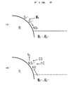
- Nitrogen dioxide (NO 2 ) is bonded with barium oxide (BaO) while being oxidized on the surface of platinum (Pt) to thereby form nitric acid ion (NO 3 - ).
- nitrogen oxides (NOx) in the exhaust gas are stored in the storage-reduction NOx catalyst as nitric acid ion (NO 3- ).
- nitrogen oxides (NOx) stored in the storage-reduction NOx catalyst in the form of nitric acid ion (NO 3- ) becomes nitrogen dioxide (NO 2 ) or nitrogen monoxide (NO) and are discharged from the storage-reduction NOx catalyst.
- nitrogen oxides (NOx) discharged from the storage-reduction NOx catalyst 20 reacts with a reducing component included in the exhaust gas (for example, activated species of hydrocarbons (HC) or carbon monoxide (CO) partially reduced by reacting with oxygen O 2- or O 2- on platinum (Pt) of the storage-reduction NOx 20) and is reduced to nitrogen (N 2 ).
- a reducing component included in the exhaust gas for example, activated species of hydrocarbons (HC) or carbon monoxide (CO) partially reduced by reacting with oxygen O 2- or O 2- on platinum (Pt) of the storage-reduction NOx 20
- hydrocarbons (HC) and carbon monoxide (CO) in the exhaust gas are oxidized by reacting with O 2 - or O 2- on platinum (Pt), and when hydrocarbons (HC) and carbon monoxide (CO) still remain even in the case in which O 2 - or O 2- on platinum (Pt) has been consumed thereby, the hydrocarbons (HC) and carbon monoxide (CO) react with nitrogen oxides (NOx) discharged from the storage-reduction NOx catalyst 20 and nitrogen oxides (NOx) discharged from the internal combustion engine 1, and as a result, nitrogen oxides (NOx) are reduced into nitrogen (N 2 ).
- NOx nitrogen oxides
- the NOx storage ability of the storage-reduction NOx catalyst 20 is saturated and nitrogen oxides (NOx) in the exhaust gas are emitted into the atmosphere without being removed or purified by the storage-reduction NOx catalyst 20.
- the mixture having the lean air/fuel ratio is burned and in accordance therewith in the most operating region, the air/fuel ratio of the exhaust gas becomes the lean air/fuel ratio and therefore, the NOx storage ability of the storage-reduction NOx catalyst 20 is easy to saturate.
- the storage-reduction NOx catalyst 20 when the storage-reduction NOx catalyst 20 is applied to a lean burn internal combustion engine such as a diesel engine, it is necessary to turn the air/fuel ratio of exhaust gas to the theoretical air/fuel ratio or the rich air/fuel ratio at a predetermined timing before the NOx storage ability of the storage-reduction NOx catalyst 20 is saturated.
- a reducing-agent supplying mechanism for adding fuel (gas oil) constituting a reducing-agent in exhaust gas flowing in the exhaust passage upstream from the storage-reduction NOx catalyst 20.
- the reducing-agent supplying mechanism is provided with a reducing-agent injection valve 28 in which an injection hole is attached to a cylinder head of the internal combustion engine 1 to face inside of the exhaust manifold 18, a reducing-agent supplying passage 29 for conducting fuel discharged from the above-described fuel pump 6 to the reducing-agent injection valve 28, a flow-regulating valve 30 provided at a middle of the reducing-agent supplying passage 29 for regulating a flow rate of fuel flowing in the reducing-agent supplying passage 29, a shut-off valve 31 provided at the reducing-agent supplying passage 29 upstream from the flow-regulating valve 30 for shutting off flow of fuel in the reducing-agent supplying passage 29 and a reducing-agent pressure sensor 32 attached to the reducing-agent supplying passage 29 upstream from the flow-regulating valve 30 for outputting an electric signal in correspondence with pressure in the reducing-agent supplying passage 29.
- the reducing-agent injection valve 28 is attached to the cylinder head such that the injection hole of the reducing-agent injection valve 28 is projected to the exhaust port of the cylinder 2 downstream from a portion of the exhaust manifold 18 in contact with the EGR passage 25 and the most proximate to a portion of the exhaust manifold 18 collecting the four branch pipes and is directed to the collecting portion of the exhaust manifold 18.
- a first (#1) cylinder 2 is disposed at a position most proximate to the aggregating portion of the exhaust manifold 18 among the four cylinders 2 of the internal combustion engine 1 and therefore, the reducing-agent injection valve 28 is attached to the exhaust port of the first (#1) cylinder 2.
- the reducing-agent injection valve 28 is attached to the exhaust port of such cylinder 2.
- the reducing-agent injection valve 28 may be attached to penetrate a water jacket (not shown diagrammatically) formed in the cylinder head or proximately to the water jacket to thereby cool the reducing-agent injection valve 28 by utilizing cooling water flowing in the water jacket.
- the reducing-agent supplying mechanism when the flow-regulating valve 30 is opened, fuel at high pressure discharged from the fuel pump 6 is applied to the reducing-agent injection valve 28 via the reducing-agent supplying passage 29. Further, when pressure of fuel applied to the reducing-agent injection valve 28 reaches valve opening pressure or higher, the reducing-agent injection valve 28 is opened and fuel as reducing-agent is injected into the exhaust manifold 18.
- the exhaust gas having the rich air/fuel ratio formed in this way flows from the turbine housing 15b into the storage-reduction NOx catalyst 20 via the exhaust pipe 19 and reduces nitrogen oxides (NOx) stored in the storage-reduction NOx catalyst 20 into nitrogen (N 2 ) while being discharged.
- NOx nitrogen oxides
- the internal combustion engine 1 constituted as described above, is also installed with an electronic control unit (ECU) 35 for controlling the internal combustion engine 1.
- the ECU 35 is a unit for controlling an operational condition of the internal combustion engine 1 and an operating state of the internal combustion engine 1 in accordance with a request of a driver.
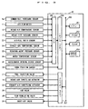
- the ECU 35 is connected with various sensors of a common rail pressure sensor 4a, an air flow meter 11, an intake-air temperature sensor 12, an intake pipe pressure sensor 17, an air/fuel ratio sensor 23, an exhaust gas temperature sensor 24, the reducing-agent pressure sensor 32, a crank position sensor 33, a water temperature sensor 34 and an accelerator opening degree sensor 36 via electric wirings and output signals of the various sensors are inputted to the ECU 35.
- the ECU 35 is connected with fuel injection valves 3, an intake-air throttling actuator 14, an exhaust-gas throttling actuator 22, an EGR valve 26, a flow-regulating valve 30 and the shut-off valve 31 via electric wirings and the respective portions can be controlled by the ECU 35.
- the ECU 35 is provided with a CPU 351, a ROM 352, a RAM 353, a backup RAM 354, an input port 356 and an output port 357 and is provided with an A/D converter (A/D) 355 connected to the input port 356.
- A/D A/D converter
- the input port 356 inputs an output signal of a sensor for outputting a signal in a digital signal type such as the crank position sensor 33 and transmits the output signal to the CPU 351 or the RAM 353.
- the input port 356 inputs output signals of sensors for outputting signals in an analog signal type such as the common rail pressure sensor 4a, the air flow meter 11, the intake-air temperature sensor 12, the intake pipe pressure sensor 17, the air/fuel ratio sensor 23, the exhaust-gas temperature sensor 24, the reducing-agent pressure sensor 32, the water temperature sensor 34 and the accelerator opening degree sensor 36 via the A/D 355 and transmits the output signals to the CPU 351 or the RAM 353.
- an analog signal type such as the common rail pressure sensor 4a, the air flow meter 11, the intake-air temperature sensor 12, the intake pipe pressure sensor 17, the air/fuel ratio sensor 23, the exhaust-gas temperature sensor 24, the reducing-agent pressure sensor 32, the water temperature sensor 34 and the accelerator opening degree sensor 36 via the A/D 355 and transmits the output signals to the CPU 351 or the RAM 353.
- the output port 357 is connected with the fuel injection valves 3, the intake-air throttling actuator 14, the exhaust-gas throttling actuator 22, the EGR valve 26, the flow-regulating valve 30 and the shut-off valve 31 via electric wirings and transmits a control signal outputted from the CPU 351 to the fuel injection valves 3, the intake-air throttling actuator 14, the exhaust-gas throttling actuator 22, the EGR valve 26, the flow-regulating valve 30 or the shut-off valve 31.
- the ROM 352 is stored with a leak of reducing-agent determining control routine for determining leakage of the reducing-agent in the reducing-agent adding mechanism in addition to various application programs such as a fuel injection valve control routine for controlling the fuel injection valve 3, an intake throttling control routine for controlling the intake-air throttling valve 13, an exhaust throttling control routine for controlling the exhaust-gas throttling valve 21, an EGR control routine for controlling the EGR valve 26 and a reducing-agent adding control routine for controlling the flow-regulating valve 30.
- a fuel injection valve control routine for controlling the fuel injection valve 3
- an intake throttling control routine for controlling the intake-air throttling valve 13
- an exhaust throttling control routine for controlling the exhaust-gas throttling valve 21
- EGR control routine for controlling the EGR valve 26
- a reducing-agent adding control routine for controlling the flow-regulating valve 30.
- the ROM 352 is stored with various control maps in addition to the above-mentioned application programs.
- the control maps include a fuel injection amount control map showing a relationship between the operational state of the internal combustion engine 1 and a basic fuel injection amount (basic fuel injection period), a fuel injection timing control map showing a relationship between the operational state of the internal combustion engine 1 and a basic fuel injection timing, an intake-air throttling valve opening degree control map showing a relationship between the operational state of the internal combustion engine 1 and a target opening degree of the intake-air throttling valve 13, an exhaust-gas throttling valve opening degree control map showing a relationship between the operational state of the internal combustion engine 1 and a target opening degree of the exhaust-gas throttling valve 21, an EGR valve opening degree control map showing a relationship between the operational state of the internal combustion engine 1 and a target opening degree of the EGR valve 26 and a flow-regulating valve control map showing a relationship between the operational state of the internal combustion engine 1 and a valve opening timing of the flow-regulating valve 30.
- the RAM 353 is stored with the output signals from the respective sensors and calculation results of the CPU 351.
- the calculation result is an engine revolution speed calculated on the basis oftemporal intervals of outputting pulse signals by the crank position sensor 33.
- the data is rewritten to newest data every time of outputting the pulse signal by the crank position sensor 33.
- the backup RAM 354 is an involatile memory capable of storing data even after operation of the internal combustion engine 1 has been stopped.
- the CPU 351 is operated in accordance with the application programs stored to the ROM 352 and executes leak of reducing-agent determining control constituting the gist of the present invention in addition to the fuel injection valve control, intake throttling control, exhaust throttling control, the EGR control and the reducing-agent adding control.
- the CPU 351 firstly determines a fuel amount injected from the fuel injection valve 3 and successively determines a timing of injecting fuel from the fuel injection valve 3.
- the CPU 351 reads the engine revolution speed and the output signal (accelerator opening degree) of the accelerator opening degree sensor 36 stored to RAM 353.
- the CPU 351 makes access to the fuel injection amount control map and calculates the basic fuel injection amount (basic fuel injection period) in correspondence with the engine revolution speed and the accelerator opening degree.
- the CPU 351 corrects the basic fuel injection period on the basis of values of the output signals of the air flow meter 11, the intake-air temperature sensor 12 and the water temperature sensor 34 and determines a final fuel injection period.
- the CPU 351 makes access to the fuel injection start timing control map and calculates the basis fuel injection timing in correspondence with the engine revolution speed and the accelerator opening degree.
- the CPU 351 corrects the basic fuel injection timing with values of the output signals of the air flow meter 11, the intake-air temperature sensor 12 and the water temperature sensor 34 as parameters and determines final fuel injection timing.
- the CPU 351 compares the fuel injection timing with output signals of the crank position sensor 33, and starts applying drive power to the fuel injection valve 3 at a time when the output signal of the crank position sensor 33 coincides with the fuel injection start timing.
- the CPU 351 stops applying the drive power with respect to the fuel injection valve 3 when the time from when an application of the drive power to the fuel injection valve 3 has been started, reached the fuel injection period.
- the CPU 351 calculates a target idling revolution speed of the internal combustion engine 1 with a value of the output signal of the water temperature sensor 34 and operational states of accessories operated by utilizing running torque of the crankshaft such as a compressor of a vehicular air-conditioning apparatus, as parameters. Further, the CPU 351 controls the fuel injection amount by feedback control such that an actual idling revolution speed coincides with the target idling revolution speed.
- the CPU 351 reads out, for example, the engine revolution speed and the accelerator opening degree stored to RAM 353.
- the CPU 351 makes access to the intake-air throttling valve opening degree control map and calculates a target intake-air throttling valve opening degree in correspondence with the engine revolution speed and the accelerator opening degree.
- the CPU 351 applies drive power in correspondence with the target intake-air throttling valve opening degree to the intake-air throttling actuator 14.
- the CPU 351 may detect an actual opening degree of the intake-air throttling valve 13 and may control the intake-air throttling actuator 14 by feedback control on the basis of a difference between the actual opening degree of the intake-air throttling valve 13 and the target intake-air throttling valve opening degree.
- the CPU 351 controls the exhaust-gas throttling actuator 22 to drive the exhaust-gas throttling valve 21 in a valve closing direction when the internal combustion engine 1 is brought into a warming-up operational state after cold start or when a heater for a vehicular compartment is brought into an operational state.
- load of the internal combustion engine 1 is increased and the fuel injection amount is increased in correspondence therewith.
- a heat generating amount of the internal combustion engine 1 is increased, warming-up of the internal combustion engine 1 is expedited and a heat source of the heater for a vehicular compartment is ensured.
- the CPU 351 reads out the engine revolution speed, the output signal of the water temperature sensor 34 (cooling water temperature) and the output signal of the accelerator opening degree sensor 36 (accelerator opening degree) stored to RAM 353 and determines whether conditions of executing the EGR control are established.
- the cooling water temperature is equal to or higher than predetermined temperature, that the internal combustion engine 1 is operated continuously for a predetermined period or more from starting the engine and that an amount of changing the accelerator opening degree is a positive value.
- the CPU 351 When it is determined that the conditions of executing the EGR control have been established, the CPU 351 makes access to the EGR valve opening degree control map with the engine revolution speed and the accelerator opening degree as parameters and calculates a target EGR valve opening degree in correspondence with the engine revolution speed and the accelerator opening degree. The CPU 351 applies drive power in correspondence with the target EGR valve opening degree to the EGR valve 26. Meanwhile, when it is determined that the conditions of executing the EGR control have not been established, The CPU 351 controls the EGR valve 26 to maintain in a fully closed state.
- the CPU 351 may carry out so-called EGR valve feedback control for controlling the opening degree of the EGR valve 26 by feedback control with an intake-air amount of the internal combustion engine 1 as a parameter.
- the CPU 351 determines a target intake-air amount of the internal combustion engine 1 with the accelerator opening degree and the engine revolution speed as parameters.
- a relationship among the accelerator opening degree, the engine revolution speed and the target intake-air amount may previously be formed in a map, and the target intake-air amount may be calculated from the map, the accelerator opening degree and the engine revolution speed.
- the CPU 351 reads out a value of the output signal of the air flow meter 11 (actual intake-air amount) stored to RAM 353 and compares an actual intake-air amount and the target intake-air amount.
- the CPU 351 closes the EGR valve 26 by a predetermined amount. At this occasion, an amount of EGR gas flowed from the EGR passage 25 into the intake manifold 8 is decreased and an amount of EGR gas intaken to the cylinder 2 of the internal combustion engine 1 is decreased accordingly. As a result, an amount of fresh air intaken into the cylinder 2 of the internal combustion engine 1 is increased by an amount of decreased EGR gas.
- the CPU 351 opens the EGR valve 26 by a predetermined amount.
- the amount of EGR gas flowed from the EGR passage 25 into the intake manifold 8 is increased and the amount of EGR gas intaken to the cylinder 2 of the internal combustion engine 1 is increased accordingly.
- the amount of fresh air intaken to the cylinders 2 of the internal combustion engine 1 is decreased by an amount of increased EGR gas.
- the CPU 351 firstly determines whether conditions of adding the reducing-agent are established.
- the conditions of adding the reducing-agent for example, there can be exemplified conditions that the storage-reduction NOx catalyst 20 is brought into an active state, that a value of the output signal of the exhaust-gas temperature sensor 24 (exhaust temperature) is equal to or smaller than a predetermined upper limit value and that there is not carried out temperature elevating control or control of recovering a SO x poisoning in order to recover the storage-reduction NOx catalyst 20 from the SO x poisoning.
- the CPU 351 controls the flow rate controlling valve 30 such that the air-fuel ratio of exhaust gas flowing into the storage-reduction NOx catalyst 20, becomes the theoretical air/fuel ratio or the rich air/fuel ratio in spike at a comparatively short period to thereby discharge and reduce nitrogen oxides (NOx) stored in the storage-reduction NOx catalyst 20 in a short period.
- NOx nitrogen oxides
- the CPU 351 reads out the engine revolution speed, the output signal of the accelerator opening degree sensor 36 (accelerator opening degree), the value of the output signal of the air flow meter 11 (intake-air amount) and the fuel injection amount stored in the RAM 353.
- the CPU 351 makes access to the flow-regulating valve control map of ROM 352 with the engine revolution speed, the accelerator opening degree, the intake-air amount and the fuel injection amount as parameters and calculates a timing of opening the flow-regulating valve 30.
- the CPU 351 opens the flow-regulating valve 30 in accordance with the valve opening timing.
- the reducing-agent injected from the reducing-agent injection valve 28 into the exhaust manifold 18, is mixed with exhaust gas flowed from the upstream side of the exhaust manifold 18 to thereby form exhaust gas having the theoretical air/fuel ratio or the rich air/fuel ratio and the exhaust gas having the theoretical air/fuel ration or the rich air/fuel ratio flows into the storage-reduction NOx catalyst 20.
- the reducing-agent adding mechanism when the 30 is opened, a portion of fuel discharged from the fuel pump 6 is supplied to the reducing-agent injection valve 28 via the reducing-agent supplying passage 29 and when pressure of fuel applied to the reducing-agent injection valve 28 becomes equal to or higher than valve opening pressure thereby, the reducing-agent injection valve 28 is opened and fuel as the reducing-agent is injected into the exhaust manifold 18.
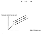
- the drive source is constituted by the running torque of the crankshaft and therefore, the discharging pressure of the fuel pump 6 is changed in accordance with the engine revolution speed and the pressure corresponding pump in the reducing-agent supplying passage 29 upstream from the flow regulating valve 30 is changed also in accordance with the engine revolution speed as shown by Fig. 4.
- the CPU 351 inputs the output signal value (adding fuel pressure) of the reducing-agent pressure sensor 32 when the flow-regulating valve 30 is brought into the valve closing state, calculates the pressure corresponding pump in correspondence with the engine revolution speed at the time point and compares the adding fuel pressure and the pressure corresponding pump to thereby determine leakage of the reducing-agent.
- pressure of fuel may be changed by an external factor such as temperature of a wall face of the reducing-agent supplying passage 29 or outside temperature and therefore, it is preferable that the CPU 351 determines that the reducing-agent is leaked when the adding fuel pressure is lower than the pressure corresponding pump by the predetermined pressure or more.
- the relationship between the engine revolution speed and the pressure corresponding pump may previously be calculated experimentally and the relationship may be formed in a map and stored to the ROM 352.
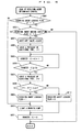
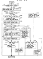
- the flowchart shown by Fig. 5 is a flowchart showing the leak of reducing-agent determining control routine.
- the leak of reducing-agent determining control routine is a routine repeatedly executed by the CPU 351 at every predetermined period (for example, every time of outputting a predetermined number of pulse signals by the crank position sensor 33).
- the CPU 351 determines whether "1" is stored at a reducing-agent leakage flag storing region set in the RAM 353.
- the reducing-agent leakage flag storing region is a storing region set with "1" when leakage of the reducing-agent (fuel) is determined in the reducing-agent adding mechanism and reset to "0" when the reducing-agent is determined not to leak.
- the reducing-agent adding execution flag storing region is a storing region set with "1" when addition of the reducing-agent is executed in a separate reducing-agent adding control routine and is reset to "0" when addition of the reducing-agent stops executing.
- the CPU 351 regards that the flow-regulating valve 30 is not brought into the valve closing state and execution of the routine is temporarily finished.
- the CPU 351 makes access to the RAM 353 and reads out the newest output signal values of the engine revolution speed and the reducing-agent pressure sensor 32 (adding fuel pressure).
- the CPU 351 makes access to the map showing the relationship between the engine revolution speed and the pressure corresponding pump and calculates the pressure corresponding pump in correspondence with the engine revolution speed read in S503.
- the CPU 351 determines whether difference pressure provided by subtracting the adding fuel pressure read in S503 from the pressure corresponding pump calculated in S504, is higher than predetermined pressure.
- the CPU 351 regards that leakage of fuel is not caused in the reducing-agent adding mechanism and proceeds to S508 and resets "0" to the reducing-agent leakage flag storing region of the RAM 353 to thereby finish executing the routine.
- the CPU 531 sets "1" into the reducing-agent leakage flag storing region of the RAM 353.
- the CPU 351 lights a warning lamp (not shown diagrammatically) provided in the vehicular compartment and finishes executing the routine. Further, the CPU 351 may light the warning lamp and prohibit addition of the reducing-agent by closing the shut-off valve 31.
- the CPU 351 executes the above-described leak of reducing-agent determining control routine to thereby realize abnormality determining means according to the present invention.
- leakage of the reducing-agent in the reducing-agent adding mechanism can be detected on the basis of fuel pressure in the reducing-agent supplying passage 29 and therefore, by reflecting leakage of the reducing-agent to the reducing-agent adding control, excessive supply or addition deficiency of the reducing-agent with respect to the storage-reduction NOx catalyst 20 can be restrained and deterioration of exhaust emission can be minimized.
- leakage of the reducing-agent is detected in the reducing-agent adding mechanism
- the shut-off valve 31 is closed to thereby prohibit addition of the reducing-agent
- leakage of the reducing-agent from the reducing-agent supplying mechanism to outside or unprepared addition of the reducing-agent from the reducing-agent supplying mechanism to the exhaust manifold 18 can also be prevented.
- leakage of the reducing-agent is determined on the basis of the adding fuel pressure when the flow-regulating valve 30 is brought into the valve closing state and the shut-off valve 31 is brought into the valve opening state and accordingly, leakage of the reducing-agent is easy to detect when leakage of a comparatively large amount of the reducing-agent is caused, when leakage of a small amount of the reducing-agent is caused, there is a possibility that the discharging amount of the fuel pump 6 becomes larger than the leakage amount and there is a possibility that it is difficult to detect leakage of a small amount of the reducing-agent.
- the CPU 351 determines leakage of the reducing-agent on the basis of a change in the adding fuel pressure when the flow-regulating valve 30 is brought into the valve closing state and the shut-off valve 31 is brought into the valve closing state.
- the reducing-agent supplying passage 29 between the flow-regulating valve 30 and the shut-off valve 31 constitutes a closed space and fuel applied with the pressure corresponding pump is confined in the closed space.
- the CPU 351 closes the shut-off valve 31 for a predetermined period of time when the flow-regulating valve 30 is brought into the valve closing state, detects a change in the adding fuel pressure during the predetermined period of time and determines that leakage of the reducing-agent is caused at the reducing-agent supplying mechanismwhen an amount of the change in the adding fuel pressure is equal to or larger than a predetermined amount.
- the flowchart shown in Fig. 6 is a flowchart showing the leak of reducing-agent determining control routine and the leak of reducing-agent determining control routine is a routine repeatedly executed at every predetermined period (for example, every time of outputting a predetermined number of pulse signals by the crank position sensor 33) by the CPU 351.
- the CPU 351 makes access to the reducing-agent leakage flag storing region of RAM 353 and determines whether "1" is stored to the reducing-agent leakage flag storing region.
- the CPU 351 closes the shut-off valve 31 and the reducing-agent supplying passage 29 from the shut-off valve 31 to the flow-regulating valve 30 constitutes the closed space.
- the CPU 351 inputs the output signal value of the reducing-agent pressure sensor 32 (adding fuel pressure of the closed space): P1 and stores the adding fuel pressure: P1 to RAM 353.
- the CPU 351 makes access to a counter storing region set to a predetermined region of RAM 353 and increments counter value: C stored to the counter storing region by 1.
- the counter storing region is a region for storing an elapse period from a time point of inputting the adding fuel pressure: P1.
- the CPU 351 determines whether the counter value: C updated in S605 is equal to or larger than a predetermined period: Cb, in other words, the elapse period from the time point of inputting the adding fuel pressure: P1 is equal to or larger than the predetermined period: Cb.
- the CPU 351 when it is determined that the counter value: C is less than the predetermined period:Cb, the CPU 351 repeatedly executes the above-described processing at S605 and thereafter until the counter value: C reaches the predetermined period: Cb or more.
- the CPU 351 proceeds to S607 and inputs again an output signal value (adding fuel pressure in the closed space) : P2 of the reducing-agent pressure sensor 32 at the time point.
- the CPU 351 reads the adding fuel pressure: P1 detected at S604 from RAM 353.
- the CPU 351 calculates an absolute value of a difference between the adding fuel pressure: P1 and the adding fuel pressure: P2 inputted at S607 and determines whether the calculated absolute value (
- the change amount: ⁇ P is a value by adding a value previously calculating experimentally a change amount of the adding fuel pressure when leakage of the reducing-agent is not caused in the reducing-agent supplying mechanism, and a margin in consideration of an external factor such as outside temperature or temperature of fuel.
- the change amount: ⁇ P may previously be stored to the predetermined region of ROM 352.
- the CPU 351 resets the reducing-agent leakage flag storing region of RAM 353 to "0".
- the CPU 351 which has finished executing the processing of S612, resets the counter value: C of the counter storing region to "0" at S611 and thereafter finishes executing the routine.
- the CPU 351 sets "1" into the reducing-agent leakage flag storing region of RAM 353.
- the CPU 351 lights a warning lamp (not shown diagrammatically) provided in the vehicular compartment.
- the CPU 351 resets the counter value: C of the counter storing region to "0".
- execution of the routine is finished.
- the closed space is formed in the reducing-agent adding mechanism, leakage of the reducing-agent is determined on the basis ofthe change in pressure during the predetermined period of the closed space and therefore, leakage of a comparatively small amount of the reducing-agent can be detected.
- the CPU 351 maintains the flow-regulating valve 30 and the shut-off valve 31 in the valve closing state during a period from when the internal combustion engine 1 stops operating until the internal combustion engine 1 is started again and determines leakage of the reducing-agent on the basis of a change in the adding fuel pressure during the period.
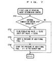
- the flowchart shown in Fig. 7 is a flowchart showing a first leak of reducing-agent determining control routine and the first leak of reducing-agent determining control routine is a routine repeatedly executed at every predetermined period (for example, every time of outputting a predetermined number of pulse signals by the crank position sensor 33) by the CPU 351.
- the flowchart shown by Fig. 8 is a flowchart showing a second leak of reducing-agent determining control routine and the second leak of reducing-agent determining control routine is a routine executed by the CPU 351 in starting the internal combustion engine 1, specifically, by switching an ignition switch (not shown diagrammatically) from OFF to ON as a trigger.
- the CPU 351 determines whether operation of the internal combustion engine 1 is stopped.
- a method of determining stoppage of operation of the internal combustion engine 1 there can be exemplified a method of determining stoppage of operation of the internal combustion engine 1 by a condition of switching an ignition switch (not shown diagrammatically) from ON to OFF, or a method of determining stoppage of operation of the internal combustion engine 1 by a condition that the engine revolution speed is lowered to less than a predetermined revolution speed.
- the CPU 351 proceeds to S702, closes both of the flow-regulating valve 30 and the shut-off valve 31 and constitutes the closed space by the passage from the flow-regulating valve 30 to the shut-off valve 31.
- the CPU 351 inputs the output signal value of the reducing-agent pressure sensor 32 (adding fuel pressure immediately after stopping to operate the engine): P1.
- the CPU 351 stores the adding fuel pressure: P1 inputted at S703 to a predetermined region of the backup RAM 354.
- the CPU 351 which has finished executing the processing of S704, finishes executing the routine.
- the CPU 351 determines whether the internal combustion engine 1 is brought into a starting state or a engine-start completed state.
- a method of determining the starting state of the internal combustion engine 1 there can be exemplified a method of determining that the internal combustion engine 1 is brought into the starting state by a condition that a starter switch (not shown diagrammatically), is switched from OFF to ON.
- a method of determining the starting finished state of the interval combustion engine 1 there can be exemplified a method of determining that the internal combustion engine 1 is brought into the starting finished state by a condition that the engine revolution speed becomes equal to or larger than a predetermined revolution speed.
- the CPU 351 proceeds to S802, makes access to the reducing-agent leakage flag storing region of RAM 353 and determines whether "1" is stored thereto.
- the CPU 351 proceeds to S810, lights a warning lamp provided in the vehicular compartment and expedites the driver of the vehicle to repair the reducing-agent supplying mechanism.
- the CPU 351 proceeds to S803 and inputs the output signal value of the water temperature sensor 34 (cooling water temperature) .
- the CPU 351 determines whether the cooling water temperature inputted at S803 is equal to or higher than predetermined temperature.
- the CPU 351 regards that an excessive period has elapsed from when operation of the internal combustion engine 1 has been stopped until the internal combustion engine 1 is started again and finishes executing the routine.
- temperature of lubricant of the internal combustion engine 1 may be used or both of the cooling water temperature and the oil temperature may be used.
- the CPU 351 regards that excessive period has not been elapsed from when operation of the internal combustion engine 1 has been stopped until the internal combustion engine 1 is started again and proceeds to S805.
- the CPU 351 maintains the valve closing state of the flow-regulating valve 30 and the shut-off valve 31 to thereby maintain the reducing-agent supplying passage 29 from the shut-off valve 31 to the flow-regulating valve 30 in the closed space.
- the CPU 351 inputs the output signal value of the reducing-agent pressure sensor 32 (adding fuel pressure of the closed space): P2.
- the CPU 351 reads the adding fuel pressure: P1 detected immediately after stopping to operate the internal combustion engine 1 from a predetermined region of the backup RAM 354.
- the CPU 351 calculates an absolute value of a difference between the adding fuel pressure detected at S806: P2 and the adding fuel pressure: P1 read at S807 and determines whether the calculated absolute value (
- ⁇ P is a value provided by adding a value of previously calculating experimentally the change amount of the adding fuel pressure when leakage of the reducing-agent is not caused in the reducing-agent supplying mechanism and a margin in consideration of an external factor such as outside temperature or temperature of fuel.
- the CPU 351 resets the reducing-agent leakage flag storing region of RAM 353 to "0".
- the CPU 351 which has finished executing the processing of S811, finishes executing the routine.
- the CPU 351 sets "1" into the reducing-agent leakage flag storing region of RAM 353.
- the CPU 351 lights a warning lamp (not shown diagrammatically) provided at the vehicular chamber.
- the CPU 351 which has finished executing the processing of S810, finishes executing the routine.
- the closed space is formed in the reducing-agent adding mechanism, leakage of the reducing-agent is determined on the basis of the change of pressure in the closed space and therefore, leakage of an extremely small amount of the reducing-agent can be detected.
- leakage of the reducing-agent can be detected on the basis of pressure of the reducing-agent in the reducing-agent supplying mechanism and therefore, leakage of the reducing-agent can be reflected to the control of adding the reducing-agent, which can contribute to restraining deterioration of exhaust emission or preventing destruction of exhaust gas purifying catalyst, which is caused by excessive supply or supply deficiency of the reducing-agent with respect to the exhaust gas purifying catalyst.
- the abnormality detecting apparatus of the reducing-agent supplying apparatus is provided with a shut-off unit shutting off flow of the reducing-agent from a reducing-agent discharging unit to a reducing-agent supplying passage
- the closed space is constituted by the passage from the shut-off unit to the reducing-agent adding unit in the reducing-agent supplying mechanism, leakage of the reducing-agent can be determined on the basis of the change in the pressure of the closed space and therefore, leakage of a comparatively small amount of the reducing-agent can be detected.
- FIG. 9 An example shown in Fig. 9 is provided with a basic constitution the same as that in Fig. 1 and therefore, with regard to an explanation thereof, please refer to the above-described explanation of Embodiment 1.
- An exhaust gas purifying apparatus of an internal combustion engine is provided with a reducing-agent supplying mechanism for adding fuel (gas oil) constituting a reducing-agent into exhaust gas flowing in the exhaust passage upstream from the storage-reduction NOx catalyst 20 and by adding fuel from the reducing-agent supplying mechanism into exhaust gas, an oxygen concentration of the exhaust gas flowing into the storage-reduction NOx catalyst 20 is reduced and a concentration of the reducing-agent is increased.
- fuel gas oil
- the reducing-agent supplying mechanism is provided with the reducing-agent injection valve 28 the injection hole of which is attached to the cylinder head of the internal combustion engine 1 to face inside of the exhaust branch 18 for injecting fuel by being opened when fuel at predetermined valve opening pressure or higher is applied, the reducing-agent supplying passage 29 for conducting fuel discharged from the above-described fuel pump 6 to the reducing-agent injection valve 28, the flow-regulating valve 30 provided at the midway of the reducing-agent supplying passage 29 for regulating the flow rate of fuel flowing in the reducing-agent supplying passage 29, the shut-off valve 31 provided at the reducing-agent supplying passage 29 upstream from the flow-regulating valve 30 for shutting off flow of fuel in the reducing-agent supplying passage 29 and the reducing-agent pressure sensor 32 attached to the reducing-agent supplying passage 29 upstream from the flow-regulating valve 30 for outputting an electric signal in correspondence with pressure in the reducing-agent supplying passage 29.
- the fuel pump 6 corresponds to reducing-agent discharging unit according to the present invention
- the reducing-agent injection valve 28 corresponds to the reducing-agent adding unit according to the present invention
- the flow-regulating valve 30 corresponds to a passage opening/closing valve according to the present invention
- the reducing-agent pressure sensor 32 corresponds to pressure detecting means according to the present invention.
- the reducing-agent supplying mechanism constituted in this way, when the flow-regulating valve 30 is opened, fuel at high pressure discharged from the fuel pump 6 is applied to the reducing-agent injection valve 28 via the reducing-agent supplying passage 29. Further, when pressure of fuel applied to the reducing-agent injection valve 28 reaches valve opening pressure or higher, the reducing-agent injection valve 28 is opened and fuel constituting the reducing-agent is injected into the exhaust manifold 18.
- the exhaust gas having the rich air/fuel ratio formed in this way flows from the turbine housing 15b to the storage-reduction NOx catalyst 20 via the exhaust pipe 19 and is reduced into nitrogen (N 2 ) while discharging nitrogen oxides (NOx) absorbed to the storage-reduction NOx catalyst 20.
- the internal combustion engine 1 constituted as described above is also provided with the electronic control unit (ECU) 35 for controlling the internal combustion engine 1.
- the ECU 35 is a unit for controlling the operational state of the internal combustion engine 1 in accordance with the operational conditions of the internal combustion engine 1 and request of the driver.
- the constitution is the same as that of Embodiment 1 and according to the ECU 35, the output signals of the various sensors are inputted to the ECU 35.
- the CPU 351 is operated in accordance with application programs stored to ROM 352 and executes the fuel injection valve control, the intake throttling control, the exhaust throttling control, the EGR control, the NOx purifying control and the abnormality determining control. These controls are basically the same as the controls in Embodiment 1.
- the CPU 351 executes so-called rich spike control for constituting an air/fuel ratio of exhaust gas flowing into the storage-reduction NOx catalyst 20 by a rich air/fuel ratio in spike (in short period of time) at a comparatively short period.
- the CPU 351 determines whether rich spike control executing conditions are established at respective predetermined period.
- rich spike control executing conditions for example, there can be exemplified a condition that the storage-reduction NOx catalyst 20 is brought into an active state, that a control for resolving catalytic poison is not executed, or that the output signal value of the exhaust-gas temperature sensor 24 (exhaust gas temperature) is equal to or smaller than a predetermined upper limit value.
- the CPU 351 When it is determined that the above-described rich spike control executing conditions are established, the CPU 351 temporarily constitutes a predetermined target rich air/fuel ratio by an air/fuel ratio of exhaust gas flowing into the storage-reduction NOx catalyst 20 by controlling the flow-regulating valve 30 to inject fuel in spike from the reducing-agent injection valve 28.
- the CPU 351 reads the engine revolution speed, the output signal of the accelerator opening degree sensor 36 (accelerator opening degree), the output signal value of the air flow meter 11 (intake-air amount) and the fuel injection amount stored to RAM 353.
- the CPU 351 makes access to the reducing-agent adding amount control map of ROM 352 with the engine revolution speed, the accelerator opening degree, the intake-air amount and the fuel injection amount as parameters and calculates an amount of adding the reducing-agent necessary for constituting the air/fuel ratio of exhaust gas by a previously set target rich air/fuel ratio (target addition amount).
- the CPU 351 makes access to the flow-regulating valve control map of ROM 352 with the target addition amount as a parameter and calculates a valve opening period (target valve opening period) of the flow-regulating valve 30 necessary for injecting the reducing-agent having the target addition amount from the reducing-agent injection valve 28.
- the CPU 351 opens the flow-regulating valve 30.
- fuel at high pressure discharged from the fuel pump 6 is supplied to the reducing-agent injection valve 28 via the reducing-agent supplying passage 29 and accordingly, pressure of fuel applied to the reducing-agent injection valve 28 reaches the valve opening pressure or higher and the reducing-agent injection valve 28 is opened.
- the CPU 351 closes the flow-regulating valve 30 when the target valve opening period has elapsed from a time point that the flow-regulating valve 30 has been opened. In this case, supply of the reducing-agent from the fuel pump 6 to the reducing-agent injection valve 28 is shut off and therefore, pressure of fuel applied to the reducing-agent injection valve 28 becomes lower than the valve opening pressure and the reducing-agent injection valve 28 is closed.
- the target addition amount of fuel is injected from the reducing-agent injection valve 28 into the exhaust manifold 18. Further, the reducing-agent injected from the reducing-agent injection valve 28 is mixed with exhaust gas which has flowed from upstream side of the exhaust manifold 18 to thereby form a mixture of the target rich air/fuel ratio and flows to the storage-reduction NOx catalyst 20.
- the CPU 351 carries out abnormality determination of the flow-regulating valve 30 and the reducing-agent injection valve 28 on the basis of pressure detected by the reducing-agent pressure sensor 32 during a period in which the flow-regulating valve 30 is brought into the valve opening state (hereinafter, referred to as valve opening period), pressure detected by the reducing-agent pressure sensor 32 before the valve opening period and pressure detected by the reducing-agent pressure sensor 32 after the valve opening period.
- the position of the sensor 32 in the case of Fig. 9 differs from that in the case of Fig. 1 and accordingly, a method of the abnormality determination also differs.
- the flow-regulating valve 30 when the flow-regulating valve 30 is opened, the reducing-agent supplying passage 29 from the fuel pump 6 to the reducing-agent injection valve 28 is brought into a conductive state and fuel discharged from the fuel pump 6 is supplied to the reducing-agent injection valve 8. Further, when pressure of fuel applied to the reducing-agent injection valve 28 becomes equal to or higher than the valve opening pressure, the reducing-agent injection valve 28 is opened and fuel constituting the reducing-agent is injected into the exhaust manifold 18.
- a closed space is constituted by the reducing-agent supplying passage 29 from the flow-regulating valve 30 to the reducing-agent injection valve 28 and therefore, pressure of fuel downstream from the flow-regulating valve 30 becomes constant pressure lower than the valve opening pressure (hereinafter, referred to as normal pressure under the valve closing condition).
- the above-described closed space is maintained up to a timing of opening the flow-regulating valve 30 at a succeeding time and therefore, pressure of fuel downstream from the flow-regulating valve 30 before the valve opening period of the flow-regulating valve 30 and after the valve opening period, becomes the normal pressure under the valve closing condition.
- pressure of fuel downstream from the flow-regulating valve 30 becomes the normal pressure under the valve closing condition before the valve opening period of the flow-regulating valve 30, becomes the normal pressure under the valve opening condition during the valve opening period of the flow-regulating valve 30, and is not lowered to the normal pressure under the valve closing condition within the predetermined period from a time point that the flow-regulating valve 30 has been closed after the valve opening period.
- the reducing-agent injection valve 28 when the reducing-agent injection valve 28 is brought into a failure in opening the valve, in other words, when the reducing-agent injection valve 28 is not brought into a fully closed state even in the case in which pressure of fuel applied to the reducing-agent injection valve 28 becomes lower than the valve opening pressure, the reducing-agent injection valve 28 is brought into an always valve opening state and therefore, before and after the valve opening period of the flow-regulating valve 30, the closed space is not constituted by the reducing-agent supplying passage 29 from the flow-regulating valve 30 to the reducing-agent injection valve 28 and pressure of fuel before and after the valve opening period becomes lower than the normal pressure under the valve closing condition.
- the flow-regulating valve 30 when the flow-regulating valve 30 is brought into an operational failure in the valve closing state, in other words, when the flow-regulating valve 30 is fixed in the valve closing state, the reducing-agent supplying passage 29 from the fuel pump 6 to the reducing-agent injection valve 28, becomes an always shut-off state, fuel discharged from the fuel pump 6 is not applied to the reducing-agent injection valve 28 and accordingly, pressure of fuel applied to the reducing-agent injection valve 28 does not becomes equal to or higher than the valve opening pressure and the reducing-agent supplying passage 29 from the flow-regulating valve 30 to the reducing-agent injection valve 28 becomes an always closed space.
- the CPU 351 can detect abnormality of the flow-regulating valve 30 or the reducing-agent injection valve 28 by monitoring fuel pressure detected by the reducing-agent pressure sensor 32 before the valve opening period, during the valve opening period and after the valve opening period of the flow-regulating valve 30, reason of causing the abnormality can be specified, thereby, the abnormality determining means according to the present invention is realized.
- the CPU 351 may close the shut-off valve 31 to thereby prohibit execution of the rich spike control, and/or may inform abnormality of the reducing-agent supplying mechanism to the driver of the vehicle by lighting a warning lamp separately provided in the vehicular chamber to thereby expedite the drive to repair the reducing-agent supplying mechanism.
- a timing of detecting fuel pressure during the valve opening period is preferably set to a timing after elapse of a predetermined period from a timing of opening the flow-regulating valve 30. This is because more or less period is taken from a time point that the flow-regulating valve 30 is opened until a time point that the reducing-agent injection valve 28 is opened (from the time point that the flow-regulating valve 30 is opened until a time point that pressure of fuel downstream from flow-regulating valve 30 becomes the normal pressure under the valve opening condition) even when the flow-regulating valve 30 and the reducing-agent injection valve 28 are normal.
- the timing of detecting the fuel pressure after the valve opening period is a timing after elapse of a predetermined period from the timing of closing the flow-regulating valve 30. This is because more or less period is taken from a time point that the flow-regulating valve 30 is closed until a time point that the reducing-agent injection valve 28 is closed (from the time point that the flow-regulating valve 30 is closed until a time point that pressure of fuel downstream from the flow-regulating valve 30 becomes the normal pressure under the valve closing condition) even when the flow regulating vale 30 and the reducing-agent injection valve 28 are normal.
- the CPU 351 determines whether abnormality determining execution conditions are established.
- abnormality determining execution conditions there can be exemplified conditions that the timing is immediately after stopping the engine, that the flow-regulating valve 30 is brought into the valve closing state, that the shut-off valve 31 is brought into the valve opening state and that the output signal value of the reducing-agent pressure sensor 32 is predetermined pressure.
- the above-described predetermined pressure is provided with a value substantially equal to pressure detected by the reducing-agent pressure sensor 32 when the fuel pump 6 is brought into the operational state and the flow-regulating valve 30 is closed (for example, 0.7 MPa, hereinafter, referred to as "operating time reducing-agent pressure") .
- the drive source is constituted by a portion of output of the internal combustion engine 1 and immediately after the internal combustion engine 1 is brought into an operation stop state, the fuel pump 6 is rotated by inertia and therefore, the output signal value of the reducing-agent pressure sensor 32, in other words, pressure of the reducing-agent at the reducing-agent supplying passage 29 between the shut-off valve 31 and the flow-regulating valve 30, is not lowered immediately.
- the above-described abnormality determining execution conditions are established by constituting the reducing-agent supplying mechanism such that the shut-off valve 31 is brought into the valve opening state immediately after stopping operation of the internal combustion engine 1 and the flow-regulating valve 30 is maintained in the valve closing state.
- the CPU 351 lights a warning lamp (not shown diagrammatically) in order to call driver's attention.
- the CPU 351 controls to close the shut-off valve 31 while maintaining the valve closing state of the flow-regulating valve 30.
- the reducing-agent supplying passage 29 from the fuel pump 6 to the reducing-agent injection valve 28 is partitioned into three spaces with the shut-off valve 31 and the flow-regulating valve 30 as boundaries.
- the reducing-agent supplying passage 29 from the shut-off valve 31 to the flow-regulating valve 30 when the flow-regulating valve 30 and the shut-off valve 31 are brought into the valve closing state is referred to as an upstream side closed space portion and the reducing-agent supplying passage 29 from the flow-regulating valve 30 to the reducing-agent injection valve 28 is referred to as a downstream side closed space portion.
- pressure of the reducing-agent at the upstream side closed space portion becomes operating time reducing-agent pressure (for example, 0.7 MPa) and pressure of the reducing-agent at the downstream side closed space portion becomes the valve opening pressure of the reducing-agent injection valve 28 (for example, 0.2 MPa) . Further, pressure of the reducing-agent in the reducing-agent supplying passage 29 upstream from the upstream side closed space portion becomes pressure substantially equal to the operating time reducing-agent pressure.
- the CPU 351 controls to close the flow-regulating valve 30 while maintaining the shut-off valve 31 at the valve closing state and controls to close the flow-regulating valve 30 immediately thereafter.
- the flow-regulating valve 30 is opened, the upstream side closed space portion and the downstream side closed space portion are communicated with each other to thereby form one closed space by the reducing-agent supplying passage 29 from the shut-off valve 31 to the reducing-agent injection valve 28.
- the reducing-agent is injected from the reducing-agent injection valve 28 to the exhaust manifold 18, pressure of the reducing-agent in the above-described closed space is gradually lowered and finally becomes equal to the valve opening pressure of the reducing-agent injection valve 28 (for example, 0.2 MPa).
- the CPU 351 controls to close the flow-regulating valve 30 and partitions the reducing-agent supplying passage 29.
- pressure of the reducing-agent in the upstream side closed space portion becomes a value lower than the operating time reducing-agent pressure and higher than the valve opening pressure (for example, 0.4 MPa, hereinafter, referred to as "normal pressure under the valve opening condition").
- valve opening condition for example, 0.4 MPa
- pressure of the reducing-agent at the downstream side closed space portion is gradually lowered from the normal pressure under the valve opening condition (for example, 0.4 MPa) and becomes the valve opening pressure (for example, 0.2 MPa).
- the CPU 351 determines abnormality of the flow-regulating valve 30 or the reducing-agent injection valve 28 on the basis of the output signal value of the reducing-agent pressure sensor 32 after the flow-regulating valve 30 has been controlled to close.
- the reducing-agent supplying passage 29 from the shut-off valve 31 to the reducing-agent injection valve 28 is not partitioned into two closed spaces but constitutes one closed space.
- Pressure of the reducing-agent in the closed space is lowered to the valve opening pressure of the reducing-agent injection valve 28 (for example, 0.2 MPa).
- the upstream side closed space portion and the downstream side closed space portion are not communicated with each other and pressure of the reducing-agent in the upstream side closed space portion remains unchanged. Therefore, the upstream side closed space portion maintains the operating time reducing-agent pressure (for example, 0.7 MPa).
- the flow-regulating valve 30 is opened in the above-described rich spike control, the reducing-agent at high pressure discharged from the fuel pump 6 is applied to the reducing-agent injection valve 28, and in that case, when clogging is caused in the reducing-agent injection valve 28, the reducing-agent is not injected from the reducing-agent injection valve 28.
- the reducing-agent supplying passage 29 from the flow-regulating valve 30 to the reducing-agent injection valve 28 constitutes a closed space and therefore, pressure of the reducing-agent in the closed space maintains the operating time reducing-agent pressure higher than the valve opening pressure (for example, 0.7 MPa).
- the output signal value of the reducing-agent pressure sensor 32 shows a behavior common to that in the case in which the flow-regulating valve 30 is brought into the operational failure in the valve opening state as shown by Fig. 17.
- the CPU 351 carries out opening/closing control of the flow-regulating valve 30 at two times.
- the shut-off valve 31 when the shut-off valve 31 is not abnormal, in the case in which the flow-regulating valve 30 is opened and the upstream side closed space portion and the downstream side closed space portion are communicated with each other, the reducing-agent is injected from the reducing-agent injection valve 28 at the respective times.
- pressure of the reducing-agent in the reducing-agent supplying passage 29 from the shut-off valve 31 to the reducing-agent injection valve 28 is lowered.
- the output signal value of the reducing-agent pressure sensor 32 is the predetermined pressure, by controlling to open and close the flow-regulating valve 30 and monitoring the output signal value of the reducing-agent pressure sensor 32 after controlling to open and close the flow regulating vale 30, abnormality of the shut-off valve 31, the flow-regulating valve 30 or the reducing-agent injection valve 28 can be determined to some degree.
- the CPU 351 determines whether the internal combustion 1 is brought into an operation stopping state.
- the CPU 351 temporarily finishes executing the routine and proceeds to S2002 when it is determined that the internal combustion engine 1 is brought into the operation stopping state.
- the CPU 351 inputs the output signal value of the reducing-agent pressure sensor 32 (reducing-agent pressure at the reducing-agent supplying passage 29 upstream from the flow-regulating valve 30): Pb.
- the CPU 351 determines whether pressure of the reducing-agent inputted at S2002 is equal to the operating time normal pressure (for example, 0.7 MPa).
- the CPU 351 proceeds to S2019, regards that leakage of the reducing-agent is caused upstream from the flow-regulating valve 30 and finishes executing the routine. Further, when it is determined that pressure of the reducing-agent is equal to the predetermined pressure, the CPU 351 proceeds to S2004.
- the CPU 351 closes the shut-off valve 31 and establishes the above-described abnormality determining execution conditions.
- the CPU 351 controls to open the flow-regulating valve 30 and controls to close the flow-regulating valve 30 immediately thereafter.
- the control is referred to as valve opening/closing control of the flow-regulating valve 30.
- the CPU 351 inputs the output signal value: Pa of the reducing-agent pressure sensor 32 after controlling to open and close the flow-regulating valve 30.
- the CPU 351 determines whether pressure of the reducing-agent: Pa inputted at S2006 is equal to the normal pressure under the valve opening condition (for example, 0.4 MPa).
- the CPU 351 determines whether pressure of the reducing-agent: Pa is equal to pressure of the reducing-agent: Pb before controlling to open and close the flow-regulating valve 30.
- the CPU 351 determines whether pressure of the reducing-agent: Pa inputted at S2006 is lower than the normal pressure under the valve opening condition (for example, 0.4 MPa).
- the CPU 351 proceeds to S2018, regards that the reducing-agent injection valve 28 is abnormal and finishes executing the routine.
- the valve opening pressure of the reducing-agent injection valve 28 becomes higher than that in normal time by reason of ageing change or mixing of foreign matters.
- pressure of the reducing-agent at the downstream side closed space portion becomes pressure higher than the valve opening pressure when the reducing-agent injection valve 28 is normal (for example, 0.5 through 0.6 MPa).
- the upstream side closed space portion maintains the operating time reducing-agent pressure (for example, 0.7 MPa) until the flow-regulating valve 30 is controlled to open. Thereafter, when the flow-regulating valve 30 is controlled to open and the upstream side closed space portion and the downstream side closed space portion are communicated with each other, pressure of the reducing-agent in the reducing-agent supplying passage 29 from the shut-off valve 31 to the reducing-agent injection valve 28, becomes pressure between pressure higher than the valve opening pressure when the reducing-agent injection valve 28 is normal and the operating time reducing-agent pressure. The pressure at this occasion becomes pressure higher than the normal pressure (for example, 0.4 MPa) when opening the valve.
- the normal pressure for example, 0.4 MPa
- the CPU 351 inputs the output signal value: Pc of the reducing-agent pressure sensor 32 after controlling to open and close the flow-regulating valve 30.
- the CPU 351 is determined whether pressure of the reducing-agent: Pc inputted at S2010 is lower than the normal pressure under the valve opening condition (for example, 0.4 MPa).
- the abnormality determining means By executing the abnormality determining control routine by the CPU 351, the abnormality determining means according to the present invention is realized.
- the reducing-agent supplying mechanism having the reducing-agent injection valve 28 attached to the exhaust manifold 18, the reducing-agent supplying passage 29 for conducting a portion of fuel discharged from the fuel pump 6 to the reducing-agent injection valve 28, the flow-regulating valve 30 provided at the midway of the reducing-agent supplying passage 29 for regulating an amount of the reducing-agent injected from the reducing-agent injection valve 28 and the shut-off valve 31 provided at the reducing-agent supplying passage 29 upstream from the flow-regulating valve 30 for shutting off the reducing-agent supplying passage 29, on the basis of the output signal of the reducing-agent pressure sensor 32 arranged between the shut-off valve 31 and the flow-regulating valve 30, abnormality of the flow-regulating valve 30, abnormality of the reducing-agent injection valve 28 and abnormality of the shut-off valve 31 can be identified to some degree.
- the amount of the reducing-agent controlled by the flow-regulating valve 30 in Embodiment 5, is controlled by the reducing-agent injection valve 28.
- the flow-regulating valve 30 when the flow-regulating valve 30 is opened, fuel at high pressure discharged from the fuel pump 6 is applied to the reducing-agent injection valve 28 via the reducing-agent supplying passage 29.
- the reducing-agent injection valve 28 is opened at the time point that the pressure of the reducing-agent applied to the reducing-agent injection valve 28 becomes higher than the valve opening pressure and injects fuel as the reducing-agent into the exhaust branch 18.
- the flow-regulating valve 30 is omitted and at the reducing-agent injection valve 28, fuel at high pressure discharged from the fuel pump 6 is directly applied to the reducing-agent injection valve28viathereducing-agentsupplying passage 29. Further, when the reducing-agent injection valve 28 is opened, fuel at high pressure is injected into the exhaust manifold 18.
- the CPU 351 reads the engine revolution speed, the output signal of the accelerator opening degree sensor 36 (accelerator opening degree), the output signal value of the air flow meter 11 (intake-air amount) and the fuel injection amount stored to RAM 353.
- the CPU 351 makes access to the reducing-agent adding amount control map of ROM 352 with the engine revolution speed, the accelerator opening degree, the intake-air amount and the fuel injection amount as parameters and calculates an amount of adding the reducing-agent necessary for constituting an air-fuel ratio of exhaust gas by a previously set target rich air/fuel ratio (target adding amount).
- the CPU 351 makes access to the flow-regulating valve control map of ROM 352 with the target adding amount as a parameter and calculates the valve opening period of the reducing-agent injection valve 28 necessary for injecting a target adding amount of the reducing-agent from the reducing-agent injection valve 28 (target valve opening period).
- the CPU 351 opens the reducing-agent injection valve 28.
- the CPU 351 closes the reducing-agent injection valve 28 when the target valve opening period has elapsed from a time point that the reducing-agent injection valve 28 has been opened.
- the target adding amount of fuel is injected from the reducing-agent injection valve 28 into the exhaust manifold 18. Further, the reducing-agent injected from the reducing-agent injection valve 28 is mixed with exhaust gas flowing from the upstream side of the discharge manifold 18, forms a mixture having the target rich air/fuel ratio and flows into the storage-reduction NOx catalyst 20.
- the CPU 351 determines whether the abnormality determining execution conditions are established.
- the abnormality determining executing conditions there can be exemplified conditions that the engine is brought into a state immediately after stopping thereof, that the shut-off valve 31 is brought into the valve opening state and that the output signal value of the reducing-agent pressure sensor 32 is predetermined pressure.
- the predetermined pressure is provided with a value substantially equal to pressure detected by the reducing-agent pressure sensor 32 when the fuel pump 6 is brought into the operating state and the reducing-agent injection valve 28 is closed (for example, 0.7 MPa, hereinafter, referred to as "operating time reducing-agent pressure").
- the drive source is constituted by a portion of output of the internal combustion engine 1
- the fuel pump 6 is rotated by inertia and therefore, the output signal value of the reducing-agent pressure sensor 32, that is, pressure of the reducing-agent at the reducing-agent supplying passage 29 between the shut-off valve 31 and the reducing-agent injection valve 28, is not lowered immediately.
- the above-described abnormality determination executing conditions are established by constituting the reducing-agent supplying mechanism such that the shut-off valve 31 maintains the valve opening state and the reducing-agent injection valve 28 maintains the valve closing state immediately after stopping operation of the internal combustion engine 1.
- the CPU 351 lights a warning lamp (not shown diagrammatically) and calls the driver's attention.
- the CPU 351 controls to close the shut-off valve 31 while maintaining the reducing-agent injection valve 28 in the valve closing state.
- the reducing-agent supplying passage 29 from the fuel pump 6 to the reducing-agent injection valve 28 is partitioned into two spaces with the flow-regulating valve 30 as a boundary.
- the reducing-agent supplying passage 29 from the shut-off valve 31 to the reducing-agent injection valve 28 when the reducing-agent injection valve 28 and the shut-off valve 31 are brought into the valve closing state is referred to as a closed space portion.
- pressure of the reducing-agent at the closed space portion becomes the operating time reducing-agent pressure (for example, 0.7 MPa). Further, pressure of the reducing-agent in the reducing-agent supplying passage 29 upstream from the closed space portion becomes pressure substantially equal to the operating time reducing-agent pressure.
- the CPU 351 controls to open the reducing-agent injection valve 28 while maintaining the shut-off valve 31 in the valve closing state and controls to close the reducing-agent injection valve 28 immediately thereafter.
- the reducing-agent injection valve 28 When the reducing-agent injection valve 28 is opened, the reducing-agent is injected from the reducing-agent injection valve 28 to the exhaust manifold 18 and pressure of the reducing-agent in the closed space is gradually lowered and finally becomes equal to pressure in the exhaust manifold 18.
- the CPU 351 controls to close the reducing-agent injection valve 28. Further, The CPU 351 determines abnormality of the reducing-agent injection valve 28 on the basis of the output signal value of the reducing-agent pressure sensor 32 after the reducing-agent injection valve 28 has been controlled to close. At this occasion, when the shut-off valve 31 and the reducing-agent injection valve 28 are normal, pressure of the reducing-agent in the closed space becomes a value lower than the operating time reducing-agent pressure (for example, 0.4 MPa, hereinafter, referred to as "normal pressure under the valve opening condition").
- the operating time reducing-agent pressure for example, 0.4 MPa
- the output signal value of the reducing-agent pressure sensor 32 shows a behavior as shown in Fig. 24.
- the output signal value of the reducing-agent pressure sensor 32 shows a behavior as shown by Fig. 25.
- the reducing-agent is not injected from the reducing-agent injection valve 28 and pressure of the reducing-agent in the closed space portion is maintained at the operation time reducing-agent pressure (for example, 0.7 MPa).
- the output signal value of the reducing-agent pressure sensor 32 shows a behavior common to that when the reducing-agent injection valve 28 is brought into the operational failure in the valve closing state as shown by Fig. 25.
- the CPU 351 controls to open and close the reducing-agent injection valve 28 at two times.
- the reducing-agent injection valve 28 is opened and the reducing-agent is injected from the reducing-agent injection valve 28 at the respective times.
- pressure of the reducing-agent in the reducing-agent supplying passage 29 from the shut-off valve 31 to the reducing-agent injection valve 28 is lowered.
- shut-off valve 31 when the shut-off valve 31 is brought into the operational failure in the valve opening state, even when The CPU 351 controls to open the shut-off valve 31, the space from the fuel pump 6 to the reducing-agent injection vale 28 is brought into an always communicated state.
- the reducing-agent injection valve 28 is controlled to open and the reducing-agent is injected from the reducing-agent injection valve 28 under the state, pressure of the reducing-agent in the reducing-agent supplying passage 29 is lowered.
- the output signal value of the reducing-agent pressure sensor 32 is predetermined pressure, by controlling to open and close the reducing-agent injection valve 28 and monitoring the output signal value of the reducing-agent pressure sensor 32 after controlling to open and close the reducing-agent injection valve 28, abnormality of the shut-off valve 31 and the reducing-agent injection valve 28 can be discriminated.
- Fig. 22 is a flowchart showing the abnormality determining control routine and the abnormality determining control routine is a routine executed when the internal combustion engine 1 is brought into the operation stopping state.
- the CPU 351 determines whether the internal combustion engine 1 is brought into the operation stopping state.
- the CPU 351 inputs the output signal value of the reducing-agent pressure sensor 32 (pressure of the reducing-agent at the reducing-agent supplying passage 29 upstream from the reducing-agent injection valve 28): Pb.
- the CPU 351 determines whether pressure of the reducing-agent inputted at S2202 is predetermined pressure (for example, 0.7 MPa).
- the CPU 351 proceeds to S2219, regards that leakage of the reducing-agent is caused upstream from the reducing-agent injection valve 28 and finishes executing the routine. Further, when it is determined that pressure of the reducing-agent is equal to the predetermined pressure, the CPU 351 proceeds to S2204.
- the CPU 351 closes the shut-off valve 31 and establishes the above-described abnormality determining execution conditions.
- the CPU 351 controls to open the reducing-agent injection valve 28 and controls to close the reducing-agent injection valve 28 immediately thereafter.
- the control is referred to as control of opening and closing the reducing-agent injection valve 28.
- the CPU 351 inputs the output signal value: Pa of the reducing-agent pressure sensor 32 after controlling to open and close the reducing-agent injection valve 28.
- the CPU 351 determines whether pressure of the reducing-agent: Pa inputted at S2206 is equal to the normal pressure under the valve opening condition (for example, 0.4 MPa).
- the CPU 351 determines whether pressure of the reducing-agent: Pa is equal to pressure of the reducing-agent: Pb before controlling to open and close the reducing-agent injection valve 28.
- the CPU 351 determines whether pressure of the reducing-agent Pa inputted at the S2206 is lower than the normal pressure under the valve opening condition (for example, 0.4 MPa).
- the CPU 351 determines that pressure of the reducing-agent: Pa inputted at S2206 is not lower than the normal pressure under the valve opening condition (for example, 0.4 MPa) the CPU 351 proceeds to S2218, regards that the reducing-agent injection valve 28 is abnormal and finishes executing the routine.
- the operation regards that an amount of the reducing-agent injected in opening the reducing-agent injection valve 28 is smaller than that in the normal time by reason of ageing change or mixing of foreign matters.
- pressure of the reducing-agent in the closed space portion becomes pressure higher than the valve opening pressure when the reducing-agent injection valve 28 is normal (for example, 0.5 through 0. 6 MPa).
- the CPU 351 inputs an output signal value: Pc of the reducing-agent pressure sensor 32 after controlling to open and close the reducing-agent injection valve 28.
- the CPU 351 determines whether pressure of the reducing-agent: Pc inputted at S2210 is lower than the normal pressure under the valve opening condition (for example, 0.4 MPa).
- the case in which it is determined that pressure of the reducing-agent: Pc is lower than the normal pressure under the valve opening condition is a case in which pressure of the reducing-agent: Pc is equal to the normal pressure under the valve opening condition and the CPU 351 proceeds to S2213, regards that the shut-off valve 31 is brought into the operational failure in the valve opening state and finishes executing the routine.
- the abnormality determining means By executing the abnormality determining control routine by the CPU 351 in this way, the abnormality determining means according to the present invention is realized.
- the reducing-agent supplying mechanism having the reducing-agent injection valve 28 attached to the exhaust manifold 18, the reducing-agent supplying passage 29 for conducting a portion of fuel discharged from the fuel pump 6 to the reducing-agent injection valve 28, and the shut-off valve 31 provided at the reducing-agent supplying passage 29 upstream from the reducing-agent injection valve 28 for shutting off the reducing-agent supplying passage 29, on the basis of the signal of the reducing-agent pressure sensor 32 arranged between the shut-off valve 31 and the reducing-agent injection valve 28, abnormality of the reducing-agent injection valve 28 and the shut-off valve 31 can be identified.
- the driver of the vehicle can recognize the abnormality at an early stage or can discover an abnormal portion in repair time at an early stage.
- the reducing-agent supplying mechanism having the reducing-agent adding unit arranged at the exhaust passage upstream from the exhaust gas purifying catalyst, the reducing-agent discharging unit for discharging the reducing-agent at predetermined discharging pressure, the reducing-agent supplying passage for conducting the reducing-agent discharged from the reducing-agent discharging unit to the reducing-agent adding unit, an amount controlling valve provided at the midway of the reducing-agent supplying passage and the shut-off valve provided at the reducing-agent supplying passage upstream from the amount controlling valve, abnormality of the reducing-agent adding unit and abnormality of the amount control valve can be identified.
- a reducing-agent supplying apparatus of the present invention for supplying a reducing-agent to an exhaust gas purifying catalyst, detects abnormality such as leakage of the reducing-agent and contributes to restraining of deterioration of exhaust gas emission and destruction of the exhaust gas purifying catalyst caused by the abnormality and includes the exhaust gas purifying catalyst provided at an exhaust passage of an internal combustion engine for purifying harmful gas components in exhaust gas under presence of the reducing-agent, a reducing-agent supplying mechanism for supplying the reducing-agent to the exhaust passage upstream from the exhaust gas purifying catalyst, pressure detecting sensor for detecting pressure of the reducing-agent in the reducing-agent supplying mechanism and ECU for determining abnormality of the reducing-agent supplying mechanism on the basis of pressure detected by the pressure detecting sensor.
Landscapes
- Engineering & Computer Science (AREA)
- Chemical & Material Sciences (AREA)
- Combustion & Propulsion (AREA)
- Mechanical Engineering (AREA)
- General Engineering & Computer Science (AREA)
- Chemical Kinetics & Catalysis (AREA)
- Exhaust Gas After Treatment (AREA)
- Exhaust Gas Treatment By Means Of Catalyst (AREA)
Applications Claiming Priority (6)
| Application Number | Priority Date | Filing Date | Title |
|---|---|---|---|
| JP2000223049A JP3558019B2 (ja) | 2000-07-24 | 2000-07-24 | 還元剤供給装置の異常検出装置 |
| JP2000223049 | 2000-07-24 | ||
| JP2000325623A JP3514230B2 (ja) | 2000-10-25 | 2000-10-25 | 内燃機関の排気浄化装置 |
| JP2000325623 | 2000-10-25 | ||
| JP2001010663A JP3473583B2 (ja) | 2000-07-24 | 2001-01-18 | 内燃機関の排気浄化装置 |
| JP2001010663 | 2001-01-18 |
Publications (2)
| Publication Number | Publication Date |
|---|---|
| EP1176292A1 true EP1176292A1 (de) | 2002-01-30 |
| EP1176292B1 EP1176292B1 (de) | 2006-09-13 |
Family
ID=27344153
Family Applications (1)
| Application Number | Title | Priority Date | Filing Date |
|---|---|---|---|
| EP01117847A Expired - Lifetime EP1176292B1 (de) | 2000-07-24 | 2001-07-23 | Vorrichtung zur Abgasreinigung für eine Brennkraftmaschine |
Country Status (4)
| Country | Link |
|---|---|
| EP (1) | EP1176292B1 (de) |
| JP (1) | JP3473583B2 (de) |
| KR (1) | KR100446843B1 (de) |
| DE (1) | DE60122984T2 (de) |
Cited By (25)
| Publication number | Priority date | Publication date | Assignee | Title |
|---|---|---|---|---|
| US6519935B2 (en) * | 1999-07-19 | 2003-02-18 | Siemens Aktiengesellschaft | Device and method for exhaust-gas aftertreatment in an internal-combustion engine |
| EP1211396A3 (de) * | 2000-12-01 | 2003-05-14 | Toyota Jidosha Kabushiki Kaisha | Abgasreinigungsvorrichtung einer Brennkraftmaschine |
| WO2003072916A1 (en) * | 2002-02-26 | 2003-09-04 | Denso Corporation | Control device and control method for internal combustion engine |
| EP1505271A1 (de) * | 2003-08-06 | 2005-02-09 | Toyota Jidosha Kabushiki Kaisha | Methode zur Bestimmung eines Reduktionsmittelzufuhrfehlers bei einem Abgasreinigungskatalysator sowie entsprechende Vorrichtung |
| WO2006040086A1 (de) * | 2004-10-13 | 2006-04-20 | L'orange Gmbh | Einrichtung zur dosierten einspritzung eines reduktionsmittels in den abgastrakt einer brennkraftmaschine |
| EP1655461A1 (de) * | 2004-11-04 | 2006-05-10 | Mitsubishi Fuso Truck and Bus Corporation | Einrichtung zur Regelung der Abgasemissionen einer Brennkraftmaschine |
| WO2007109233A1 (en) * | 2006-03-17 | 2007-09-27 | Continental Automotive Systems Us, Inc. | Diesel exhaust dosing structure |
| WO2008130284A1 (en) * | 2007-04-19 | 2008-10-30 | Volvo Lastvagnar Ab | Method and arrangement for monitoring of injector |
| EP1845244A3 (de) * | 2006-04-11 | 2009-04-29 | Toyota Jidosha Kabushiki Kaisha | Abgasreinigungssystem eines Verbrennungsmotors |
| WO2009115715A1 (fr) * | 2008-03-20 | 2009-09-24 | Renault S.A.S | Procede de detection de defaillance d'une electrovanne d'injection a l'echappement de moteur a combustion |
| EP2034147A4 (de) * | 2006-06-26 | 2009-11-25 | Nissan Diesel Motor Co | Vorrichtung zur steuerung von motorabgasemissionen |
| EP2128395A4 (de) * | 2007-01-26 | 2010-01-20 | Bosch Corp | Verstopfungsbeurteilungsvorrichtung für ein reduktionsmitteleinspritzventil und verstopfungsbeurteilungsverfahren für ein reduktionsmitteleinspritzventil |
| EP2034148A4 (de) * | 2006-06-26 | 2010-02-10 | Nissan Diesel Motor Co | Motorabgasreinigungsvorrichtung |
| US8261536B2 (en) | 2008-06-19 | 2012-09-11 | Ford Global Technologies, Llc | Method to detect fuel vaporizer coking |
| US8347605B2 (en) | 2005-08-15 | 2013-01-08 | Continental Automotive Systems Us, Inc. | Automotive diesel exhaust HC dosing valve for use with diesel particulate filter systems |
| CN103261601A (zh) * | 2010-12-27 | 2013-08-21 | 博世株式会社 | 排气净化系统及排气净化系统的控制方法 |
| EP2653686A4 (de) * | 2010-12-16 | 2014-10-29 | Isuzu Motors Ltd | Einspritzsystem einer abgasleitung |
| US9151201B2 (en) | 2006-11-08 | 2015-10-06 | Continental Automotive Systems, Inc. | Laser welded automotive diesel exhaust HC dosing valve |
| DE102005009464B4 (de) * | 2005-03-02 | 2016-07-21 | Robert Bosch Gmbh | Verfahren zur Diagnose eines Systems zur Dosierung von Reagenzmittel und Druckluft in den Abgasbereich einer Brennkraftmaschine und Vorrichtung zur Durchführung des Verfahrens |
| DE102006013293B4 (de) * | 2006-03-23 | 2016-08-18 | Robert Bosch Gmbh | Verfahren zur Diagnose einer Abgasnachbehandlungsvorrichtung und Vorrichtung zur Durchführung des Verfahrens |
| EP3505745A1 (de) * | 2017-12-26 | 2019-07-03 | Toyota Jidosha Kabushiki Kaisha | Vorrichtung und verfahren zur diagnose von anomalien für ein additionsventil |
| CN112081654A (zh) * | 2020-09-22 | 2020-12-15 | 广州雷易科技有限公司 | 一种汽车涡轮增压器 |
| CN112943428A (zh) * | 2021-02-05 | 2021-06-11 | 广西玉柴机器股份有限公司 | 一种准确度高的发动机后处理hc喷射系统诊断方法 |
| US11401849B2 (en) | 2017-12-20 | 2022-08-02 | Isuzu Motors Limited | Internal combustion engine exhaust purification device |
| CN120626320A (zh) * | 2025-07-11 | 2025-09-12 | 万维检验认证集团有限公司 | 一种汽车内燃发动机的排放监测方法及系统 |
Families Citing this family (15)
| Publication number | Priority date | Publication date | Assignee | Title |
|---|---|---|---|---|
| AU2003299644A1 (en) * | 2002-12-17 | 2004-07-22 | Clean Diesel Technologies, Inc. | Nox control for ic engines |
| DE102004022115A1 (de) * | 2004-05-05 | 2005-11-24 | Robert Bosch Gmbh | Verfahren zum Einbringen eines Reagenzmittels in einen Abgaskanal einer Brennkraftmaschine und Vorrichtung zur Durchführung des Verfahrens |
| DE102005001119B4 (de) * | 2005-01-10 | 2018-02-15 | Robert Bosch Gmbh | Verfahren zum Betreiben einer Brennkraftmaschine und Vorrichtung zur Durchführung des Verfahrens |
| DE102006005863B4 (de) * | 2006-02-09 | 2015-04-30 | Robert Bosch Gmbh | Verfahren zur Diagnose einer Abgasbehandlungsvorrichtung und Vorrichtung zur Durchführung des Verfahrens |
| DE102006009099A1 (de) | 2006-02-28 | 2007-08-30 | Daimlerchrysler Ag | Einspritzsystem mit einer Vorrichtung zum Dosieren von Kraftstoff in ein Abgassystem einer Brennkraftmaschine und einem Verfahren hierzu |
| JP4165896B2 (ja) | 2007-02-19 | 2008-10-15 | ボッシュ株式会社 | 還元剤経路の詰まり判定装置及び還元剤経路の詰まり判定方法 |
| WO2009081228A1 (en) * | 2007-12-21 | 2009-07-02 | Renault Trucks | Apparatus and method for injection of a fluid for an exhaust gases treatment device |
| JP5093691B2 (ja) * | 2009-06-12 | 2012-12-12 | トヨタ自動車株式会社 | 還元剤供給システムの異常診断装置 |
| JP5592759B2 (ja) * | 2010-11-08 | 2014-09-17 | ボッシュ株式会社 | 還元剤噴射弁の異常判定装置及び異常判定方法並びに内燃機関の排気浄化装置 |
| JP5547815B2 (ja) * | 2010-11-08 | 2014-07-16 | ボッシュ株式会社 | 還元剤噴射弁の異常判定装置及び還元剤供給装置 |
| JP5744634B2 (ja) * | 2011-06-09 | 2015-07-08 | 日野自動車株式会社 | 燃料添加弁の故障検出装置 |
| JP5914151B2 (ja) * | 2012-05-09 | 2016-05-11 | ボッシュ株式会社 | 還元剤噴射弁の異常検出装置及び還元剤供給装置 |
| DE102017208799A1 (de) | 2017-05-24 | 2018-11-29 | Bayerische Motoren Werke Aktiengesellschaft | Abgasanlage für eine Brennkraftmaschine und Verfahren zum Überprüfen der Abgasanlage |
| JP2019094851A (ja) | 2017-11-24 | 2019-06-20 | スズキ株式会社 | 排気ガスセンサの配置構造及び排気制御システム |
| JP2019105259A (ja) * | 2017-12-14 | 2019-06-27 | トヨタ自動車株式会社 | 還元剤添加装置の異常診断装置 |
Citations (3)
| Publication number | Priority date | Publication date | Assignee | Title |
|---|---|---|---|---|
| US5367875A (en) * | 1992-12-07 | 1994-11-29 | Coltec Industries Inc | Automated catalytic reduction system |
| JPH1193641A (ja) * | 1997-09-25 | 1999-04-06 | Toyota Motor Corp | 内燃機関の排気浄化装置 |
| DE19914787A1 (de) * | 1998-04-06 | 1999-10-14 | Toyota Motor Co Ltd | Abgasreinigungssystem für einen Verbrennungsmotor |
Family Cites Families (3)
| Publication number | Priority date | Publication date | Assignee | Title |
|---|---|---|---|---|
| JPH06108825A (ja) * | 1992-09-28 | 1994-04-19 | Mitsubishi Motors Corp | 排気ガス浄化装置 |
| JP3384444B2 (ja) | 1998-11-20 | 2003-03-10 | 三菱自動車工業株式会社 | 蓄圧式燃料噴射装置 |
| JP4158272B2 (ja) | 1999-03-26 | 2008-10-01 | トヨタ自動車株式会社 | 高圧燃料噴射系の異常判定方法 |
-
2001
- 2001-01-18 JP JP2001010663A patent/JP3473583B2/ja not_active Expired - Fee Related
- 2001-07-23 EP EP01117847A patent/EP1176292B1/de not_active Expired - Lifetime
- 2001-07-23 DE DE60122984T patent/DE60122984T2/de not_active Expired - Lifetime
- 2001-07-24 KR KR10-2001-0044368A patent/KR100446843B1/ko not_active Expired - Fee Related
Patent Citations (3)
| Publication number | Priority date | Publication date | Assignee | Title |
|---|---|---|---|---|
| US5367875A (en) * | 1992-12-07 | 1994-11-29 | Coltec Industries Inc | Automated catalytic reduction system |
| JPH1193641A (ja) * | 1997-09-25 | 1999-04-06 | Toyota Motor Corp | 内燃機関の排気浄化装置 |
| DE19914787A1 (de) * | 1998-04-06 | 1999-10-14 | Toyota Motor Co Ltd | Abgasreinigungssystem für einen Verbrennungsmotor |
Non-Patent Citations (1)
| Title |
|---|
| PATENT ABSTRACTS OF JAPAN vol. 1999, no. 09 30 July 1999 (1999-07-30) * |
Cited By (38)
| Publication number | Priority date | Publication date | Assignee | Title |
|---|---|---|---|---|
| US6519935B2 (en) * | 1999-07-19 | 2003-02-18 | Siemens Aktiengesellschaft | Device and method for exhaust-gas aftertreatment in an internal-combustion engine |
| EP1211396A3 (de) * | 2000-12-01 | 2003-05-14 | Toyota Jidosha Kabushiki Kaisha | Abgasreinigungsvorrichtung einer Brennkraftmaschine |
| WO2003072916A1 (en) * | 2002-02-26 | 2003-09-04 | Denso Corporation | Control device and control method for internal combustion engine |
| US7143756B2 (en) | 2002-02-26 | 2006-12-05 | Toyota Jidosha Kabushiki Kaisha | Control device and control method for internal combustion engine |
| EP1505271A1 (de) * | 2003-08-06 | 2005-02-09 | Toyota Jidosha Kabushiki Kaisha | Methode zur Bestimmung eines Reduktionsmittelzufuhrfehlers bei einem Abgasreinigungskatalysator sowie entsprechende Vorrichtung |
| WO2006040086A1 (de) * | 2004-10-13 | 2006-04-20 | L'orange Gmbh | Einrichtung zur dosierten einspritzung eines reduktionsmittels in den abgastrakt einer brennkraftmaschine |
| EP1655461A1 (de) * | 2004-11-04 | 2006-05-10 | Mitsubishi Fuso Truck and Bus Corporation | Einrichtung zur Regelung der Abgasemissionen einer Brennkraftmaschine |
| DE102005009464B4 (de) * | 2005-03-02 | 2016-07-21 | Robert Bosch Gmbh | Verfahren zur Diagnose eines Systems zur Dosierung von Reagenzmittel und Druckluft in den Abgasbereich einer Brennkraftmaschine und Vorrichtung zur Durchführung des Verfahrens |
| US8347605B2 (en) | 2005-08-15 | 2013-01-08 | Continental Automotive Systems Us, Inc. | Automotive diesel exhaust HC dosing valve for use with diesel particulate filter systems |
| WO2007109233A1 (en) * | 2006-03-17 | 2007-09-27 | Continental Automotive Systems Us, Inc. | Diesel exhaust dosing structure |
| DE102006013293B4 (de) * | 2006-03-23 | 2016-08-18 | Robert Bosch Gmbh | Verfahren zur Diagnose einer Abgasnachbehandlungsvorrichtung und Vorrichtung zur Durchführung des Verfahrens |
| EP1845244A3 (de) * | 2006-04-11 | 2009-04-29 | Toyota Jidosha Kabushiki Kaisha | Abgasreinigungssystem eines Verbrennungsmotors |
| EP2034147A4 (de) * | 2006-06-26 | 2009-11-25 | Nissan Diesel Motor Co | Vorrichtung zur steuerung von motorabgasemissionen |
| EP2034148A4 (de) * | 2006-06-26 | 2010-02-10 | Nissan Diesel Motor Co | Motorabgasreinigungsvorrichtung |
| US7743605B2 (en) | 2006-06-26 | 2010-06-29 | Nissan Diesel Motor Co., Ltd. | Exhaust emission purifying apparatus for engine |
| CN101466924B (zh) * | 2006-06-26 | 2011-01-19 | 日产柴油机车工业株式会社 | 发动机排气净化装置 |
| US8132405B2 (en) | 2006-06-26 | 2012-03-13 | Nissan Diesel Motor Co., Ltd. | Exhaust emission purifying apparatus for engine |
| US9151201B2 (en) | 2006-11-08 | 2015-10-06 | Continental Automotive Systems, Inc. | Laser welded automotive diesel exhaust HC dosing valve |
| EP2128395A4 (de) * | 2007-01-26 | 2010-01-20 | Bosch Corp | Verstopfungsbeurteilungsvorrichtung für ein reduktionsmitteleinspritzventil und verstopfungsbeurteilungsverfahren für ein reduktionsmitteleinspritzventil |
| WO2008130294A1 (en) * | 2007-04-19 | 2008-10-30 | Volvo Lastvagnar Ab | Method and arrangement for monitoring of an injector |
| US8393141B2 (en) | 2007-04-19 | 2013-03-12 | Volvo Lastvagnar Ab | Method and arrangement for monitoring of injector |
| US8484949B2 (en) | 2007-04-19 | 2013-07-16 | Volvo Lastvagnar Ab | Method and arrangement for monitoring of an injector |
| WO2008130284A1 (en) * | 2007-04-19 | 2008-10-30 | Volvo Lastvagnar Ab | Method and arrangement for monitoring of injector |
| FR2928969A1 (fr) * | 2008-03-20 | 2009-09-25 | Renault Sas | Procede de detection de defaillance d'une electrovanne d'injection a l'echappement de moteur a combustion |
| WO2009115715A1 (fr) * | 2008-03-20 | 2009-09-24 | Renault S.A.S | Procede de detection de defaillance d'une electrovanne d'injection a l'echappement de moteur a combustion |
| US8261536B2 (en) | 2008-06-19 | 2012-09-11 | Ford Global Technologies, Llc | Method to detect fuel vaporizer coking |
| US8839603B2 (en) | 2008-06-19 | 2014-09-23 | Ford Global Technologies, Llc | Method to detect fuel vaporizer coking |
| EP2653686A4 (de) * | 2010-12-16 | 2014-10-29 | Isuzu Motors Ltd | Einspritzsystem einer abgasleitung |
| US9255511B2 (en) | 2010-12-27 | 2016-02-09 | Bosch Corporation | Exhaust purification system and method for controlling exhaust purification system |
| CN103261601B (zh) * | 2010-12-27 | 2015-11-25 | 博世株式会社 | 排气净化系统及排气净化系统的控制方法 |
| CN103261601A (zh) * | 2010-12-27 | 2013-08-21 | 博世株式会社 | 排气净化系统及排气净化系统的控制方法 |
| US11401849B2 (en) | 2017-12-20 | 2022-08-02 | Isuzu Motors Limited | Internal combustion engine exhaust purification device |
| EP3505745A1 (de) * | 2017-12-26 | 2019-07-03 | Toyota Jidosha Kabushiki Kaisha | Vorrichtung und verfahren zur diagnose von anomalien für ein additionsventil |
| CN112081654A (zh) * | 2020-09-22 | 2020-12-15 | 广州雷易科技有限公司 | 一种汽车涡轮增压器 |
| CN112081654B (zh) * | 2020-09-22 | 2021-03-19 | 广州雷易科技有限公司 | 一种汽车涡轮增压器 |
| CN112943428A (zh) * | 2021-02-05 | 2021-06-11 | 广西玉柴机器股份有限公司 | 一种准确度高的发动机后处理hc喷射系统诊断方法 |
| CN112943428B (zh) * | 2021-02-05 | 2022-04-19 | 广西玉柴机器股份有限公司 | 一种准确度高的发动机后处理hc喷射系统诊断方法 |
| CN120626320A (zh) * | 2025-07-11 | 2025-09-12 | 万维检验认证集团有限公司 | 一种汽车内燃发动机的排放监测方法及系统 |
Also Published As
| Publication number | Publication date |
|---|---|
| JP3473583B2 (ja) | 2003-12-08 |
| KR100446843B1 (ko) | 2004-09-04 |
| DE60122984T2 (de) | 2007-09-13 |
| KR20020009474A (ko) | 2002-02-01 |
| DE60122984D1 (de) | 2006-10-26 |
| EP1176292B1 (de) | 2006-09-13 |
| JP2002213231A (ja) | 2002-07-31 |
Similar Documents
| Publication | Publication Date | Title |
|---|---|---|
| EP1176292B1 (de) | Vorrichtung zur Abgasreinigung für eine Brennkraftmaschine | |
| US5461857A (en) | Engine exhaust gas purification device | |
| EP1444430B1 (de) | Abgasreinigungsvorrichtung und -verfahren für brennkraftmaschine | |
| US5551231A (en) | Engine exhaust gas purification device | |
| JP3617450B2 (ja) | 内燃機関の排気浄化装置 | |
| EP1176290B1 (de) | Abgasreinigungsvorrichtung für eine Brennkraftmaschine | |
| JP3514230B2 (ja) | 内燃機関の排気浄化装置 | |
| JP2001164999A (ja) | 排気再循環装置の詰まり検出装置 | |
| US7219491B2 (en) | Exhaust emission control apparatus of internal combustion engine and method thereof | |
| US7040087B2 (en) | Device for purifying exhaust gas for engine | |
| JP3558019B2 (ja) | 還元剤供給装置の異常検出装置 | |
| EP1211396B1 (de) | Abgasreinigungsvorrichtung einer Brennkraftmaschine | |
| JP2003148211A (ja) | 内燃機関の排気浄化装置 | |
| JP3674511B2 (ja) | 内燃機関の排気浄化装置 | |
| JP2002129996A (ja) | 内燃機関の排気浄化装置 | |
| JP2002122019A (ja) | 内燃機関の排気浄化装置 | |
| EP1512848B1 (de) | Abgasreinigungsvorrichtung sowie Verfahren zur Abgasreiningung | |
| JP3798623B2 (ja) | 内燃機関の排気浄化装置 | |
| JP4352651B2 (ja) | 内燃機関の異常判定装置 | |
| JP2003269155A (ja) | 内燃機関の排気浄化装置 | |
| JP3674507B2 (ja) | 内燃機関の排気浄化装置 | |
| JP3800065B2 (ja) | 内燃機関の排気浄化装置 | |
| JP2002161733A (ja) | 内燃機関の排気浄化装置 | |
| JP2004076684A (ja) | 内燃機関の排気浄化装置 | |
| JP3651382B2 (ja) | 内燃機関の排気浄化装置 |
Legal Events
| Date | Code | Title | Description |
|---|---|---|---|
| PUAI | Public reference made under article 153(3) epc to a published international application that has entered the european phase |
Free format text: ORIGINAL CODE: 0009012 |
|
| 17P | Request for examination filed |
Effective date: 20010723 |
|
| AK | Designated contracting states |
Kind code of ref document: A1 Designated state(s): DE FR GB Kind code of ref document: A1 Designated state(s): AT BE CH CY DE DK ES FI FR GB GR IE IT LI LU MC NL PT SE TR |
|
| AX | Request for extension of the european patent |
Free format text: AL;LT;LV;MK;RO;SI |
|
| AKX | Designation fees paid |
Free format text: DE FR GB |
|
| 17Q | First examination report despatched |
Effective date: 20041214 |
|
| GRAP | Despatch of communication of intention to grant a patent |
Free format text: ORIGINAL CODE: EPIDOSNIGR1 |
|
| GRAS | Grant fee paid |
Free format text: ORIGINAL CODE: EPIDOSNIGR3 |
|
| GRAA | (expected) grant |
Free format text: ORIGINAL CODE: 0009210 |
|
| AK | Designated contracting states |
Kind code of ref document: B1 Designated state(s): DE FR GB |
|
| REG | Reference to a national code |
Ref country code: GB Ref legal event code: FG4D |
|
| REF | Corresponds to: |
Ref document number: 60122984 Country of ref document: DE Date of ref document: 20061026 Kind code of ref document: P |
|
| ET | Fr: translation filed | ||
| PLBE | No opposition filed within time limit |
Free format text: ORIGINAL CODE: 0009261 |
|
| STAA | Information on the status of an ep patent application or granted ep patent |
Free format text: STATUS: NO OPPOSITION FILED WITHIN TIME LIMIT |
|
| 26N | No opposition filed |
Effective date: 20070614 |
|
| REG | Reference to a national code |
Ref country code: GB Ref legal event code: 746 Effective date: 20091103 |
|
| PGFP | Annual fee paid to national office [announced via postgrant information from national office to epo] |
Ref country code: GB Payment date: 20120718 Year of fee payment: 12 |
|
| PGFP | Annual fee paid to national office [announced via postgrant information from national office to epo] |
Ref country code: FR Payment date: 20120719 Year of fee payment: 12 Ref country code: DE Payment date: 20120718 Year of fee payment: 12 |
|
| GBPC | Gb: european patent ceased through non-payment of renewal fee |
Effective date: 20130723 |
|
| REG | Reference to a national code |
Ref country code: FR Ref legal event code: ST Effective date: 20140331 |
|
| PG25 | Lapsed in a contracting state [announced via postgrant information from national office to epo] |
Ref country code: DE Free format text: LAPSE BECAUSE OF NON-PAYMENT OF DUE FEES Effective date: 20140201 Ref country code: GB Free format text: LAPSE BECAUSE OF NON-PAYMENT OF DUE FEES Effective date: 20130723 |
|
| REG | Reference to a national code |
Ref country code: DE Ref legal event code: R119 Ref document number: 60122984 Country of ref document: DE Effective date: 20140201 |
|
| PG25 | Lapsed in a contracting state [announced via postgrant information from national office to epo] |
Ref country code: FR Free format text: LAPSE BECAUSE OF NON-PAYMENT OF DUE FEES Effective date: 20130731 |