EP1176314A2 - Procédé et dispositif pour compenser la compressibilité dans des commandes hydrauliques - Google Patents
Procédé et dispositif pour compenser la compressibilité dans des commandes hydrauliques Download PDFInfo
- Publication number
- EP1176314A2 EP1176314A2 EP01116889A EP01116889A EP1176314A2 EP 1176314 A2 EP1176314 A2 EP 1176314A2 EP 01116889 A EP01116889 A EP 01116889A EP 01116889 A EP01116889 A EP 01116889A EP 1176314 A2 EP1176314 A2 EP 1176314A2
- Authority
- EP
- European Patent Office
- Prior art keywords
- pressure
- piston
- valve
- compression
- displacement space
- Prior art date
- Legal status (The legal status is an assumption and is not a legal conclusion. Google has not performed a legal analysis and makes no representation as to the accuracy of the status listed.)
- Granted
Links
Images


Classifications
-
- F—MECHANICAL ENGINEERING; LIGHTING; HEATING; WEAPONS; BLASTING
- F15—FLUID-PRESSURE ACTUATORS; HYDRAULICS OR PNEUMATICS IN GENERAL
- F15B—SYSTEMS ACTING BY MEANS OF FLUIDS IN GENERAL; FLUID-PRESSURE ACTUATORS, e.g. SERVOMOTORS; DETAILS OF FLUID-PRESSURE SYSTEMS, NOT OTHERWISE PROVIDED FOR
- F15B9/00—Servomotors with follow-up action, e.g. obtained by feed-back control, i.e. in which the position of the actuated member conforms with that of the controlling member
- F15B9/02—Servomotors with follow-up action, e.g. obtained by feed-back control, i.e. in which the position of the actuated member conforms with that of the controlling member with servomotors of the reciprocatable or oscillatable type
- F15B9/08—Servomotors with follow-up action, e.g. obtained by feed-back control, i.e. in which the position of the actuated member conforms with that of the controlling member with servomotors of the reciprocatable or oscillatable type controlled by valves affecting the fluid feed or the fluid outlet of the servomotor
- F15B9/09—Servomotors with follow-up action, e.g. obtained by feed-back control, i.e. in which the position of the actuated member conforms with that of the controlling member with servomotors of the reciprocatable or oscillatable type controlled by valves affecting the fluid feed or the fluid outlet of the servomotor with electrical control means
-
- F—MECHANICAL ENGINEERING; LIGHTING; HEATING; WEAPONS; BLASTING
- F15—FLUID-PRESSURE ACTUATORS; HYDRAULICS OR PNEUMATICS IN GENERAL
- F15B—SYSTEMS ACTING BY MEANS OF FLUIDS IN GENERAL; FLUID-PRESSURE ACTUATORS, e.g. SERVOMOTORS; DETAILS OF FLUID-PRESSURE SYSTEMS, NOT OTHERWISE PROVIDED FOR
- F15B21/00—Common features of fluid actuator systems; Fluid-pressure actuator systems or details thereof, not covered by any other group of this subclass
- F15B21/08—Servomotor systems incorporating electrically operated control means
Definitions
- the invention relates to an apparatus and a method for compensation the compressibility of the hydraulic fluid in hydraulic drives with at least one displacement room.
- Hydraulic fluid is compressible within certain limits, resulting in a load stiffness significantly reduced compared to mechanical drives leads: in the event of sudden pressure changes in the at least one Displacer are the known regulations too sluggish to pass through appropriate Supply or discharge of hydraulic fluid in the displacement space the desired target position together with a cylinder Displacement forming piston or a desired target speed to hold the piston.
- DE 42 28 308 A1 describes the compensation of compressibility through piezo elements.
- the piezo elements can withstand very high forces generate in no time, but the resulting paths are very short.
- a piezo element itself is a spring. If it works against pressure, the path is further reduced as it is compressed under pressure. This has the consequence that in practice only minor Load changes that correspond to a maximum pressure change of 5 to 7 bar are compensated become. As a rule, however, there are pressure changes depending on the supply pressure required in the range of 100 bar and more. The in DE 42 28 308 control is therefore not suitable to the in the Practice requirements.
- the object of the invention is a device and to specify a method which enables the load stiffness hydraulic drives can be increased reliably and within a few milliseconds to react to load changes in order to or to compensate for speed deviations of a hydraulic drive.
- the invention is achieved by a device with the features of Claim 1 or of a method with the features of the claim 15.
- Advantageous embodiments are the subject of the dependent Dependent claims.
- the secondary claim 21 relates to one hydraulic drive with a compensation device according to the invention.
- the volume flow resulting from the pressure increase calculated, the compression coefficient and the volume below Pressure is taken into account and represents the reference variable in the control loop
- the compensation volumetric flow generated by the compensation piston is constantly compared with the setpoint (compression volume flow) and via the control circuit (three-point controller and fast control valves) tracked. The result is that exactly the volume of the working cylinder what is missing due to compression in the displacement space.
- the drive cylinder remains largely in its position.
- the compensation takes place over the entire pressure range up to the maximum load. It is both with controlled and with position-controlled systems effective. With position-controlled drives, the functions of the Position control and compressibility compensation.
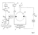
- the hydraulic drive in Fig. 1 consists of a cylinder 1 and a piston 2 guided therein, which separates two displacement spaces 3 and 4 from each other.
- the cylinder piston drive is controlled with the continuous valve 6 in a closed position control loop, by measuring the piston travel X ist with a distance measuring device 7 and comparing it with the target value X soll .
- the difference X nominal - X actual is the current error of the retracted position.
- controller 9 This is modified by a controller 9 according to modern controller concepts, for example by generating a differentiating and / or integrating component which is fed to the continuous valve 6 via an amplifier element 10, which controls the piston-cylinder unit via lines 11 and 12 in this way that the error X should - X is made zero as quickly as possible.
- the invention is intended to bring about a change in the Load F 5 of the piston 2 remains in its position or at one constant speed of the drive no drop in speed he follows.
- a piston 15 is arranged in the cylinder 14 and is held in the middle by the springs 18 and 19.
- the piston 15 separates two displacement chambers 16 and 17.
- the pressure in chamber 3 of the hydraulic drive is measured via the pressure sensor 21 and passed on via the electrical line 22. Pressure oscillations of the pressure sensor are damped by the damper element 23.
- the temporal pressure gradient is calculated in the differentiator 24.
- the compression current Q Kompr can be calculated from the pressure gradient dp 1 / dt, which vanishes due to the pressure change in the displacement space 3 over time or becomes free when the pressure decreases.
- V o is the p in the displacement chambers 3, 16, 17 under the pressure of 1 supernatant oil volume
- E ö1 is the volume compression Koeffizienz the oil filling V o, whereby the elasticity of the surrounding cylinder 1 and 14 taken into account.
- the oil filling V o is of the piston travel X is dependent
- the compression modulus E ö1 is a function of the pressure P. 1 Both influences are included in the result for Q Kompr in block 25.
- y ' is determined using a speed sensor 20 integrated in the piston chamber 17.
- the path y of the piston 15 can also be measured and converted to the speed y 'by the differentiator 26.
- the result of the difference formation Q Kompr - Q Ausgl is fed to a three-point controller 27. Is Q Compr greater than Q Equ.
- the displacement chamber 17 is connected to the pressure source P via the line 29 via a very fast switching valve 28 with switching times of 1 to 2 milliseconds.
- Piston chamber 4 is, the supply of a compensating volume flow is only too a displacement room necessary.
- the three-point controller 27 causes that Switching valve 28 of the piston 15 moves in the negative y direction, and thus a corresponding compensation volume flow from room 17 and thus room 3 is discharged.
- C is the total spring stiffness of the springs and a is the area of the piston 15.
- the switching valve 30 can optionally be replaced by an increased play between the piston 15 and the cylinder 14, as a result of which the piston 15 is centered.
- the device for increasing the dynamic load rigidity is on all types of cylinders applicable, not only to cylinders of the same area, as in FIG. 1.
- Fig. 2 the application in a differential cylinder is shown. Also Plunger cylinders with only one displacement space can be equipped with it become. Fig. 2 shows two special features. The balance cylinder 14 with Piston 15 can be integrated directly into the cylinder cover 33 on one piston side become. In addition, instead of the 3/3 switching valve in the cylinder cover 28 in Fig. 1 two 2/2-way valves 31 and 32 are integrated. This are characterized by a very small design and extremely short switching times in the range of 1 ms.
- Fig. 3 shows that the volume flow control loop for the compensating flow can also be carried out continuously.
- the constant valve 36 is controlled by the difference between the compression current Q Kompr and the compensation current Q Ausgl via the blocks 34 and 35.
- a compensation current Q compensation corresponding to the compression current Q Kompr is supplied to the displacement space 3 under pressure p 1 .
Landscapes
- Engineering & Computer Science (AREA)
- Physics & Mathematics (AREA)
- Fluid Mechanics (AREA)
- Mechanical Engineering (AREA)
- General Engineering & Computer Science (AREA)
- Chemical & Material Sciences (AREA)
- Analytical Chemistry (AREA)
- Fluid-Pressure Circuits (AREA)
- Supply Devices, Intensifiers, Converters, And Telemotors (AREA)
Applications Claiming Priority (2)
| Application Number | Priority Date | Filing Date | Title |
|---|---|---|---|
| DE2000136646 DE10036646A1 (de) | 2000-07-26 | 2000-07-26 | Vorrichtung und Verfahren zum Ausgleichen der Kompressibilität bei hydraulischen Antrieben |
| DE10036646 | 2000-07-26 |
Publications (3)
| Publication Number | Publication Date |
|---|---|
| EP1176314A2 true EP1176314A2 (fr) | 2002-01-30 |
| EP1176314A3 EP1176314A3 (fr) | 2004-01-07 |
| EP1176314B1 EP1176314B1 (fr) | 2006-02-15 |
Family
ID=7650431
Family Applications (1)
| Application Number | Title | Priority Date | Filing Date |
|---|---|---|---|
| EP20010116889 Expired - Lifetime EP1176314B1 (fr) | 2000-07-26 | 2001-07-11 | Procédé et dispositif pour compenser la compressibilité dans des commandes hydrauliques |
Country Status (2)
| Country | Link |
|---|---|
| EP (1) | EP1176314B1 (fr) |
| DE (2) | DE10036646A1 (fr) |
Cited By (1)
| Publication number | Priority date | Publication date | Assignee | Title |
|---|---|---|---|---|
| DE102006002566A1 (de) * | 2006-01-18 | 2007-07-19 | Eurocopter Deutschland Gmbh | Hydraulikanlage |
Families Citing this family (1)
| Publication number | Priority date | Publication date | Assignee | Title |
|---|---|---|---|---|
| DE102009027070A1 (de) * | 2009-06-22 | 2010-12-23 | Zf Friedrichshafen Ag | Ansteuerschaltung für einen pneumatischen oder hydraulischen Aktuator |
Family Cites Families (4)
| Publication number | Priority date | Publication date | Assignee | Title |
|---|---|---|---|---|
| US3805530A (en) * | 1971-07-29 | 1974-04-23 | Pacific Press & Shear Corp | Compensated series hydraulic system |
| DE3017080C2 (de) * | 1980-05-03 | 1985-11-28 | Deutsche Forschungs- und Versuchsanstalt für Luft- und Raumfahrt e.V., 5000 Köln | Elektrohydraulischer Stellantrieb |
| JPS6432081A (en) * | 1987-07-28 | 1989-02-02 | Tokyo Keiki Kk | Pressure flow controller for variable delivery pump |
| DE4228308A1 (de) * | 1992-08-26 | 1994-03-03 | Rexroth Mannesmann Gmbh | Hydraulische Antriebsvorrichtung, insbesondere für eine Werkzeugmaschine |
-
2000
- 2000-07-26 DE DE2000136646 patent/DE10036646A1/de not_active Withdrawn
-
2001
- 2001-07-11 EP EP20010116889 patent/EP1176314B1/fr not_active Expired - Lifetime
- 2001-07-11 DE DE50108932T patent/DE50108932D1/de not_active Expired - Lifetime
Cited By (3)
| Publication number | Priority date | Publication date | Assignee | Title |
|---|---|---|---|---|
| DE102006002566A1 (de) * | 2006-01-18 | 2007-07-19 | Eurocopter Deutschland Gmbh | Hydraulikanlage |
| US7581486B2 (en) | 2006-01-18 | 2009-09-01 | Eurocopter Deutschland Gmbh | Hydraulic system |
| DE102006002566B4 (de) * | 2006-01-18 | 2014-11-13 | Eurocopter Deutschland Gmbh | Hydraulikanlage |
Also Published As
| Publication number | Publication date |
|---|---|
| EP1176314A3 (fr) | 2004-01-07 |
| DE50108932D1 (de) | 2006-04-20 |
| DE10036646A1 (de) | 2002-02-14 |
| EP1176314B1 (fr) | 2006-02-15 |
Similar Documents
| Publication | Publication Date | Title |
|---|---|---|
| DE3744469A1 (de) | Fluessigkeitsgefuellte aufhaengung und zugehoerige steuervorrichtung | |
| EP2039582A2 (fr) | Amortisseur hydraulique actif et mécanisme de commande hydraulique | |
| DE3638574A1 (de) | Anordnung zur drucksteuerung eines daempfungszylinders fuer die abfederung von fahrzeugen | |
| AT516316B1 (de) | Verfahren zur Steuerung einer hydraulisch angetriebenen Maschine | |
| LU87794A1 (fr) | Proportional-wegeventil in sitzbauweise | |
| WO2017025302A1 (fr) | Commande de soupape pneumatique | |
| EP4367405B1 (fr) | Dispositif d'actionnement pour au moins un consommateur actionné fluidiquement | |
| DE3244191A1 (de) | Mit einer konstantzugregelung versehener hydraulischer zylinder | |
| EP0745189B1 (fr) | Dispositif de regulation du debit total d'au moins deux pompes hydrostatiques a cylindree variable | |
| EP1731669A1 (fr) | Rouleau à compensation de flèche | |
| DE4327313C2 (de) | Verfahren zur Druckregelung einer hydrostatischen Maschine mit verstellbarem Fördervolumen | |
| EP1176314B1 (fr) | Procédé et dispositif pour compenser la compressibilité dans des commandes hydrauliques | |
| DE202011052463U1 (de) | Hydropulsvorrichtung, insbesondere Innendruckpulser | |
| DE1296982B (de) | Hydraulischer Servomechanismus | |
| DE3738241A1 (de) | Elektrohydraulische vorrichtung zur lastunabhaengigen regelung eines volumenstromes proportional zu einem eingangssignal | |
| DE3644737C2 (de) | Steueranordnung für mindestens zwei von mindestens einer Pumpe gespeiste hydraulische Verbraucher | |
| DE69225392T2 (de) | Einrichtung zur Steuerung mehrerer Servomotoren | |
| DE102015215554A1 (de) | Vorrichtung und Verfahren zur Beeinflussung einer dynamischen Eigenschaft wenigstens eines beweglich gelagerten Körpers sowie deren Verwendung als variabel einstellbares Dämpfungselement | |
| DE3803490C2 (fr) | ||
| DE102004061351B3 (de) | Servohydraulischer Direktantrieb für Webschäfte | |
| EP4390198A1 (fr) | Dispositif et procédé de régulation du débit d'un fluide | |
| CH394639A (de) | Ventilgesteuerte Werkstoff-Prüfmaschine mit doppelt wirkendem und geschlossenem Druckmittelkreislauf | |
| DE2719029A1 (de) | Hydraulische regeleinrichtung | |
| DE10130597B4 (de) | Elektrohydraulischer Aktor auf Basis einer reversierbaren Flügelzellenpumpe mit unterlagerter Druckregelung | |
| DE2305825A1 (de) | Einrichtung zur einstellung der schwenkstellung einer hydrostatischen pumpe |
Legal Events
| Date | Code | Title | Description |
|---|---|---|---|
| PUAI | Public reference made under article 153(3) epc to a published international application that has entered the european phase |
Free format text: ORIGINAL CODE: 0009012 |
|
| AK | Designated contracting states |
Kind code of ref document: A2 Designated state(s): AT BE CH CY DE DK ES FI FR GB GR IE IT LI LU MC NL PT SE TR |
|
| AX | Request for extension of the european patent |
Free format text: AL;LT;LV;MK;RO;SI |
|
| PUAL | Search report despatched |
Free format text: ORIGINAL CODE: 0009013 |
|
| AK | Designated contracting states |
Kind code of ref document: A3 Designated state(s): AT BE CH CY DE DK ES FI FR GB GR IE IT LI LU MC NL PT SE TR |
|
| AX | Request for extension of the european patent |
Extension state: AL LT LV MK RO SI |
|
| 17P | Request for examination filed |
Effective date: 20040618 |
|
| 17Q | First examination report despatched |
Effective date: 20040715 |
|
| AKX | Designation fees paid |
Designated state(s): DE FR GB IT |
|
| GRAP | Despatch of communication of intention to grant a patent |
Free format text: ORIGINAL CODE: EPIDOSNIGR1 |
|
| GRAS | Grant fee paid |
Free format text: ORIGINAL CODE: EPIDOSNIGR3 |
|
| GRAA | (expected) grant |
Free format text: ORIGINAL CODE: 0009210 |
|
| AK | Designated contracting states |
Kind code of ref document: B1 Designated state(s): DE FR GB IT |
|
| REG | Reference to a national code |
Ref country code: GB Ref legal event code: FG4D Free format text: NOT ENGLISH |
|
| REF | Corresponds to: |
Ref document number: 50108932 Country of ref document: DE Date of ref document: 20060420 Kind code of ref document: P |
|
| GBT | Gb: translation of ep patent filed (gb section 77(6)(a)/1977) |
Effective date: 20060524 |
|
| PGFP | Annual fee paid to national office [announced via postgrant information from national office to epo] |
Ref country code: IT Payment date: 20060731 Year of fee payment: 6 |
|
| ET | Fr: translation filed | ||
| PLBE | No opposition filed within time limit |
Free format text: ORIGINAL CODE: 0009261 |
|
| STAA | Information on the status of an ep patent application or granted ep patent |
Free format text: STATUS: NO OPPOSITION FILED WITHIN TIME LIMIT |
|
| PGFP | Annual fee paid to national office [announced via postgrant information from national office to epo] |
Ref country code: GB Payment date: 20070119 Year of fee payment: 6 |
|
| 26N | No opposition filed |
Effective date: 20061116 |
|
| GBPC | Gb: european patent ceased through non-payment of renewal fee |
Effective date: 20070711 |
|
| PGFP | Annual fee paid to national office [announced via postgrant information from national office to epo] |
Ref country code: FR Payment date: 20070111 Year of fee payment: 6 |
|
| PG25 | Lapsed in a contracting state [announced via postgrant information from national office to epo] |
Ref country code: GB Free format text: LAPSE BECAUSE OF NON-PAYMENT OF DUE FEES Effective date: 20070711 |
|
| REG | Reference to a national code |
Ref country code: FR Ref legal event code: ST Effective date: 20080331 |
|
| PG25 | Lapsed in a contracting state [announced via postgrant information from national office to epo] |
Ref country code: FR Free format text: LAPSE BECAUSE OF NON-PAYMENT OF DUE FEES Effective date: 20070731 |
|
| PG25 | Lapsed in a contracting state [announced via postgrant information from national office to epo] |
Ref country code: IT Free format text: LAPSE BECAUSE OF NON-PAYMENT OF DUE FEES Effective date: 20070711 |
|
| PGFP | Annual fee paid to national office [announced via postgrant information from national office to epo] |
Ref country code: DE Payment date: 20200731 Year of fee payment: 20 |
|
| REG | Reference to a national code |
Ref country code: DE Ref legal event code: R071 Ref document number: 50108932 Country of ref document: DE |