EP1176327A2 - Weitwinkelgleichlaufgelenk mit Oelschmierung und Dichtungsmanchetten - Google Patents
Weitwinkelgleichlaufgelenk mit Oelschmierung und Dichtungsmanchetten Download PDFInfo
- Publication number
- EP1176327A2 EP1176327A2 EP01830468A EP01830468A EP1176327A2 EP 1176327 A2 EP1176327 A2 EP 1176327A2 EP 01830468 A EP01830468 A EP 01830468A EP 01830468 A EP01830468 A EP 01830468A EP 1176327 A2 EP1176327 A2 EP 1176327A2
- Authority
- EP
- European Patent Office
- Prior art keywords
- constant velocity
- velocity joint
- yokes
- bellows
- joint
- Prior art date
- Legal status (The legal status is an assumption and is not a legal conclusion. Google has not performed a legal analysis and makes no representation as to the accuracy of the status listed.)
- Withdrawn
Links
- 230000001681 protective effect Effects 0.000 title claims abstract description 26
- 238000005461 lubrication Methods 0.000 title claims abstract description 16
- 239000010687 lubricating oil Substances 0.000 claims abstract description 15
- 239000004519 grease Substances 0.000 claims description 11
- 230000002265 prevention Effects 0.000 claims description 5
- 230000001050 lubricating effect Effects 0.000 claims description 4
- 125000006850 spacer group Chemical group 0.000 claims description 2
- 230000000284 resting effect Effects 0.000 claims 1
- 230000002269 spontaneous effect Effects 0.000 claims 1
- 238000002955 isolation Methods 0.000 description 7
- ZZUFCTLCJUWOSV-UHFFFAOYSA-N furosemide Chemical compound C1=C(Cl)C(S(=O)(=O)N)=CC(C(O)=O)=C1NCC1=CC=CO1 ZZUFCTLCJUWOSV-UHFFFAOYSA-N 0.000 description 6
- 239000000314 lubricant Substances 0.000 description 6
- 230000005540 biological transmission Effects 0.000 description 5
- 230000007613 environmental effect Effects 0.000 description 3
- 239000002184 metal Substances 0.000 description 3
- 230000008878 coupling Effects 0.000 description 2
- 238000010168 coupling process Methods 0.000 description 2
- 238000005859 coupling reaction Methods 0.000 description 2
- 238000007689 inspection Methods 0.000 description 2
- 238000012423 maintenance Methods 0.000 description 2
- 239000003921 oil Substances 0.000 description 2
- 239000004677 Nylon Substances 0.000 description 1
- 239000006185 dispersion Substances 0.000 description 1
- 239000013536 elastomeric material Substances 0.000 description 1
- 239000012530 fluid Substances 0.000 description 1
- 239000007924 injection Substances 0.000 description 1
- 238000002347 injection Methods 0.000 description 1
- 238000003754 machining Methods 0.000 description 1
- 229920001778 nylon Polymers 0.000 description 1
- 230000000737 periodic effect Effects 0.000 description 1
- 230000000717 retained effect Effects 0.000 description 1
- 238000005096 rolling process Methods 0.000 description 1
- 238000007789 sealing Methods 0.000 description 1
- 239000000243 solution Substances 0.000 description 1
- 229920003002 synthetic resin Polymers 0.000 description 1
- 239000000057 synthetic resin Substances 0.000 description 1
Images


Classifications
-
- F—MECHANICAL ENGINEERING; LIGHTING; HEATING; WEAPONS; BLASTING
- F16—ENGINEERING ELEMENTS AND UNITS; GENERAL MEASURES FOR PRODUCING AND MAINTAINING EFFECTIVE FUNCTIONING OF MACHINES OR INSTALLATIONS; THERMAL INSULATION IN GENERAL
- F16D—COUPLINGS FOR TRANSMITTING ROTATION; CLUTCHES; BRAKES
- F16D3/00—Yielding couplings, i.e. with means permitting movement between the connected parts during the drive
- F16D3/16—Universal joints in which flexibility is produced by means of pivots or sliding or rolling connecting parts
- F16D3/26—Hooke's joints or other joints with an equivalent intermediate member to which each coupling part is pivotally or slidably connected
- F16D3/30—Hooke's joints or other joints with an equivalent intermediate member to which each coupling part is pivotally or slidably connected in which the coupling is specially adapted to constant velocity-ratio
- F16D3/32—Hooke's joints or other joints with an equivalent intermediate member to which each coupling part is pivotally or slidably connected in which the coupling is specially adapted to constant velocity-ratio by the provision of two intermediate members each having two relatively perpendicular trunnions or bearings
-
- F—MECHANICAL ENGINEERING; LIGHTING; HEATING; WEAPONS; BLASTING
- F16—ENGINEERING ELEMENTS AND UNITS; GENERAL MEASURES FOR PRODUCING AND MAINTAINING EFFECTIVE FUNCTIONING OF MACHINES OR INSTALLATIONS; THERMAL INSULATION IN GENERAL
- F16D—COUPLINGS FOR TRANSMITTING ROTATION; CLUTCHES; BRAKES
- F16D3/00—Yielding couplings, i.e. with means permitting movement between the connected parts during the drive
- F16D3/84—Shrouds, e.g. casings, covers; Sealing means specially adapted therefor
- F16D3/841—Open covers, e.g. guards for agricultural p.t.o. shafts
-
- F—MECHANICAL ENGINEERING; LIGHTING; HEATING; WEAPONS; BLASTING
- F16—ENGINEERING ELEMENTS AND UNITS; GENERAL MEASURES FOR PRODUCING AND MAINTAINING EFFECTIVE FUNCTIONING OF MACHINES OR INSTALLATIONS; THERMAL INSULATION IN GENERAL
- F16D—COUPLINGS FOR TRANSMITTING ROTATION; CLUTCHES; BRAKES
- F16D3/00—Yielding couplings, i.e. with means permitting movement between the connected parts during the drive
- F16D3/84—Shrouds, e.g. casings, covers; Sealing means specially adapted therefor
- F16D3/843—Shrouds, e.g. casings, covers; Sealing means specially adapted therefor enclosed covers
- F16D3/845—Shrouds, e.g. casings, covers; Sealing means specially adapted therefor enclosed covers allowing relative movement of joint parts due to the flexing of the cover
Definitions
- the constant velocity joint in question essentially comprises flexible protective means which are sealingly engaged with the input and output members of the joint, and which delimit a space which surrounds the joint and which can contain liquid lubricant, or lubricant which becomes fluid in normal conditions, in order to provide oil-bath lubrication of the joint.
- An advantageous embodiment is designed for a constant velocity joint of the aforesaid type, which comprises two yokes forming the input and output members of the joint, two cross journals and a central core forming a sliding housing in a transverse geometrical plane for a securing member for the ball ends of the two yokes; constant velocity joints of this kind are currently equipped for grease lubrication.
- the joint can comprise, on the central core and on the base of each of the two yokes, annular tracks for a sealed fit to the edges of protective bellows means, which delimit a space which surrounds the joint and can contain liquid lubricant for oil-bath lubrication.
- the number 1 indicates a telescopic shaft, formed by two tubular components 1A and 1B extending in the form of a telescope, with an end joint 3 at one end and a wide-angle constant velocity joint 5 at the other end; the telescopic shaft 1 is provided with a protective sleeve 7.
- the whole is essentially a known embodiment.
- the constant velocity joint 5 is of the wide-angle type; it comprises a yoke member 9, for input to the joint or output from it, this yoke having a grooved seat 9A for coupling to a transmission member with which the constant velocity joint is combined.
- the member 9 is integral (see Fig. 3 and subsequent figures) with the base 10A of a yoke 10 forming part of the said joint 5.
- the telescopic shaft 1 is engaged with a member 12 which is integral with the base 14A of a yoke 14 forming part of the said constant velocity joint.
- the two yokes 10 and 14 (see, in particular, Figs.
- the constant velocity joint also comprises a central core 16 (see also Fig. 6), which consists of two parts which are essentially symmetrical with respect to a plane which is transverse with respect to the overall axis of the joint in question when the components for input to and output from the members 9 and 12 are aligned with each other; the said two parts of the member 16 are welded together at 16S.
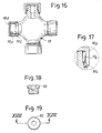
- the central core 16 has two opposing extensions 16A, the extensions of each pair forming rotary seats for a cross journal 18 (see also Figs. 16 and 17); each cross journal 18 is additionally pivoted on the corresponding yoke 10 or 14 described above.
- a securing member 20 (see also Figs. 9 and 10) extending in the form of a disc 20B having at its center a circular cylindrical through hole 20A, which houses the opposing ball ends 10B and 14B of the two yokes 10 and 14; the discoid securing member 20 is housed in such a way to be able to slide in a housing 24 which is formed by two parallel and opposing walls 24A, 24B of the two components of the central core 16; these two components are suitably machined and then welded at 16S to slidably engage the discoid securing member 20, 20B.
- the whole of what has been described up to this point is an example of a shaft with a constant velocity joint of a known type, of the class which can provide transmission even in conditions of considerable angulation, as shown in Fig. 3.
- the disc part 20B of the said discoid member 20 has (see also Figs. 9 and 10) a number of through holes 26 together with radial ducts 28 which extend between the periphery of the discoid member 20B and the central through seat 20A of the said securing member 20.
- the walls 24A and 24B - which delimit the sliding housing 24 in a plane transverse with respect to the axis of the central core 16 for the disc part 20B of the securing member 20 - have (see also Figs. 6 to 10) suitably distributed recesses 30 and 32 respectively.
- Each of the bases 10A and 14A of the yokes 10 and 14 has a track 110A, 114A which is essentially cylindrical, with an intermediate annular channel such as that indicated by 110B, for the purposes stated below; a further channel 110C is also provided adjacently to the annular track 110A of the base 10A of the yoke 10, and a similar channel is provided adjacently to the track 114A of the base 14A of the yoke 14.
- the central core 16 there are provided (see, in particular, Fig.
- Fig. 11 shows in isolation a protective bellows 36 made from elastomeric material, and particularly from a rubber resistant to lubricating oils; one of these bellows 36 is designed to be fitted on the tracks 110A, 116A; a similar protective bellows 38 is designed to be fitted on the annular tracks 114A of the base 14A of the yoke 14 and on the track 216A, 216B of the central core 16.
- the bellows 36 has an annular terminal edge 36B having an internal diameter matching that of the annular track 110A, and a second terminal edge 36C having an internal diameter matching that of the annular track 116A.
- the terminal edge 36B is provided with an internal metal ring 40, while the terminal edge 36C has an internal annular projection 42.
- the protective bellows 36 is fitted so that it extends between the base 10A of the yoke 10 and the central core 16; in particular, the edge 36B with the metal ring 40 is fitted onto the track 110A, a sealing ring being housed in the channel 110B and interacting with the inner surface of the metal ring 40.
- the terminal edge 36C of the protective bellows 36 is engaged with the annular track 116A, the internal projection 42 being housed in the annular channel 116B.
- a tightening band 44 is applied (see also Figs. 14 and 15) and is provided with a screw clamp 46 of a known type, by means of which the tightening is carried out.
- a fitting of an entirely similar type is provided for the protective bellows 38.
- Flat rings 48, 50 (see also Figs. 12 to 13A), extending approximately in planes transverse with respect to the axis of the joint in its aligned configuration, are fitted in the annular external grooves such as those indicated by 36A, 36A1, 38A, 38A1 of the protective bellows 36 and 38, before the said bellows are fitted; these flat rings 48 and 50 are made from synthetic resin (such as nylon or the like), have a radial widths approximately equal to the depths of the external grooves of the bellows, and are designed to provide a considerable degree of stability of the bellows configuration of the individual protective bellows 36 and 38, and to prevent the direct contact of the rubber surfaces of the opposing sides of the grooves.
- the flat rings 50 (see also Figs.
- Figs. 16 and 17 show one of the cross journals 18, whose ends are typically provided with needle bearings 18A or the like, with an external rolling track formed by cups 18B.
- the conventional annular seals which are usually housed in the seats 18C to retain the dense lubricant (grease) are dispensed with for the oil-bath lubrication of these bearings.
- the constant velocity joint indicated in a general way by 5 and extending essentially between the bases 10A and 14A of the yokes 10 and 14 which are integral with the input and output members such as those indicated by 9 and 12, is protected by the two bellows 36 and 38; this is because these two bellows 36 and 38 form a completely enclosed space around the constant velocity joint 5, and this space can have a part of its volume (particularly a part which is of the order of 60%) occupied by a liquid lubricant, or by a lubricant which when heated takes on a fluidity comparable to that of the liquid lubricant; thus the constant velocity joint can be lubricated essentially by the "oil-bath" system, rather than by a conventional grease lubrication system.
- a through hole is provided in the base of one of the yokes and in particular, according to the drawing, in the base 10A of the yoke 10, and is sealed by a screw plug 52 which is easily accessible through the axial grooved cavity 9A of the terminal member 9, which is provided with a conventional quick-release coupling 9X for a grooved terminal of a shaft of the transmission of which the constant velocity joint 5 forms part.
- the presence of the through holes 26 and of the radial channels 28 in the discoid member 20B, and the presence of the recesses 32 and 30 in the walls 24A and 24B of the housing 24, provide considerable possibilities for the circulation of the liquid lubricant, for lubricating the disc 20B of the securing member 20 which is movable in the sliding housing 24, and for lubricating the ball ends 10B and 14B of the yokes 10 and 14 in their common through seat 20A of the securing member 20, and in the roller bearings 18A; the whole being achieved without any need for forced circulation but simply with the aid of the movements which are imparted to the constant velocity joint both by its rotation and by the angulation of the components of the joint with respect to each other. In particular, no maintenance or frequent inspection of the oil level are required. It is sufficient to make occasional brief inspections of the bellows 36, 38 for easy identification of possible oil leaks.
- the constant velocity joint can also be produced to operate with grease lubrication; it is simply necessary to provide the described constant velocity joint - after removal of the bellows 36 and 38 - with the conventional greasers on the core 16 and with annular seals in the seats 18C and other conventional arrangements for this type of joint. It is possible to dispense with some machining operations, such as those for forming the seats for the engagement of the terminal edges of the bellows 36 and 38 on the yokes and on the central core.
- annular channel 54 is provided (see Figs. 1, 2, 3 and 6) in the central core 16 for an annular support 56 provided with a greaser 58 (Fig. 2), which is fairly easily accessible for periodic injections of lubricating grease, with a known type of arrangement, the greaser 58 being designed to lubricate only the annular groove 54, in order to permit relative angular movement between the rotating core 16 and the annular support 56, which for reasons of accident prevention must not rotate.
- a further protective bellows 60 which is fitted, in a known arrangement 62, on the protective sleeve 7 of the telescopic tube 1.
- This protective bellows 60 is engaged with the annular support 56, with which a further guard 64 of the rigid type is also engaged.
- Two flat truncated conical guards 66 and 68 can be engaged with the bases 10A and 14A of the yokes 10 and 14, as shown in the drawing, to complete the accident prevention device and to prevent contact between the internal components; in respect of this characteristic, reference should also be made to the angulated configuration shown in Fig. 3.
- the invention by providing - in place of the two bellows 36, 38 - a single bellows extending between the two bases 10A and 14A of the yokes 10 and 14, one at least of which is suitably oversized to meet the requirements of fitting.
- This single bellows in an intermediate position, can be supported on the periphery of a core suitably modified from that indicated by 16, and should be provided externally with a rigid component equivalent to that indicated by 56; the whole assembly will have equivalent functions to those of the components 56, 60 and 64.
Landscapes
- Engineering & Computer Science (AREA)
- General Engineering & Computer Science (AREA)
- Mechanical Engineering (AREA)
- Sealing Devices (AREA)
- Pivots And Pivotal Connections (AREA)
- Diaphragms And Bellows (AREA)
- Lubricants (AREA)
Applications Claiming Priority (2)
| Application Number | Priority Date | Filing Date | Title |
|---|---|---|---|
| ITFI000169 | 2000-07-24 | ||
| IT2000FI000169A IT1314869B1 (it) | 2000-07-24 | 2000-07-24 | Giunto omocinetico a grande angolazione con lubrificazione a bagnod'olio, per trasmissioni cardaniche. |
Publications (2)
| Publication Number | Publication Date |
|---|---|
| EP1176327A2 true EP1176327A2 (de) | 2002-01-30 |
| EP1176327A3 EP1176327A3 (de) | 2002-08-07 |
Family
ID=11441937
Family Applications (1)
| Application Number | Title | Priority Date | Filing Date |
|---|---|---|---|
| EP01830468A Withdrawn EP1176327A3 (de) | 2000-07-24 | 2001-07-13 | Weitwinkelgleichlaufgelenk mit Oelschmierung und Dichtungsmanchetten |
Country Status (4)
| Country | Link |
|---|---|
| US (1) | US20020010027A1 (de) |
| EP (1) | EP1176327A3 (de) |
| CA (1) | CA2353224A1 (de) |
| IT (1) | IT1314869B1 (de) |
Cited By (3)
| Publication number | Priority date | Publication date | Assignee | Title |
|---|---|---|---|---|
| WO2004020859A1 (en) * | 2002-08-28 | 2004-03-11 | Kwok-Wah Pun | Constant velocity universal joint with less axles and can bend a greater angle |
| EP1435467A1 (de) * | 2003-01-03 | 2004-07-07 | Edi Bondioli | Weitwinkelgleichlaufgelenkeinrichtung zur Verminderung der Spannung der inneren Elementen |
| DE10335551A1 (de) * | 2003-08-02 | 2005-02-24 | Gkn Driveline International Gmbh | Faltenbalg mit ineinanderliegenden Balgabschnitten |
Families Citing this family (9)
| Publication number | Priority date | Publication date | Assignee | Title |
|---|---|---|---|---|
| FR2912788A1 (fr) * | 2007-02-19 | 2008-08-22 | Blackmer Soc Par Actions Simpl | Dispositif etanche de transmission d'un mouvement de rotation a l'interieur d'une chambre |
| KR20150141269A (ko) * | 2014-06-09 | 2015-12-18 | 남양공업주식회사 | 가변형 광각 조인트 |
| IT201800009788A1 (it) | 2018-10-25 | 2020-04-25 | Edi Bondioli | Giunto omocinetico grandangolare con serbatoio di lubrificante |
| CA3133937A1 (en) * | 2019-11-07 | 2021-05-14 | Lusetti, Lea | Drive shaft with lubricated accident-prevention end protections |
| IT202000031067A1 (it) * | 2020-12-16 | 2022-06-16 | A M A S P A | Giunto cardanico doppio |
| EP4116596B8 (de) * | 2021-07-09 | 2024-01-10 | Walterscheid GmbH | Doppelkreuzgelenk mit einer radial bewegbaren zentrierscheibe für die beiden kreuzgelenke |
| FR3135767B1 (fr) * | 2022-05-20 | 2024-07-19 | Psa Automobiles Sa | JOINT DE Cardan lubrifiÉ |
| US11796009B1 (en) * | 2023-01-27 | 2023-10-24 | Ryan D. Hunter | Cover for a universal joint of a driveshaft |
| FR3162808A1 (fr) * | 2024-06-03 | 2025-12-05 | Stellantis Auto Sas | Joint de transmission |
Family Cites Families (6)
| Publication number | Priority date | Publication date | Assignee | Title |
|---|---|---|---|---|
| US2331982A (en) * | 1942-03-26 | 1943-10-19 | Corydon M Johnson | Combined universal joint and bearing |
| DE2810942C3 (de) * | 1978-03-14 | 1981-04-23 | Uni-Cardan Ag, 5200 Siegburg | Dichtungsanordnung |
| DE3921242C1 (de) * | 1989-06-29 | 1990-06-21 | Jean Walterscheid Gmbh, 5204 Lohmar, De | |
| DE4205653C2 (de) * | 1992-02-25 | 1994-02-24 | Walterscheid Gmbh Gkn | Kreuzgelenk |
| FR2729725B1 (fr) * | 1995-01-24 | 1997-04-18 | Yamajany Snc | Gaine de protection souple pour joints rotatifs articules |
| IT1288372B1 (it) * | 1996-11-08 | 1998-09-22 | Eurocardan S P A | Dispositivo di protezione a cuffia con ghiera con albero, in particolare albero cardanico. |
-
2000
- 2000-07-24 IT IT2000FI000169A patent/IT1314869B1/it active
-
2001
- 2001-07-13 EP EP01830468A patent/EP1176327A3/de not_active Withdrawn
- 2001-07-18 CA CA002353224A patent/CA2353224A1/en not_active Abandoned
- 2001-07-20 US US09/909,509 patent/US20020010027A1/en not_active Abandoned
Non-Patent Citations (1)
| Title |
|---|
| None |
Cited By (6)
| Publication number | Priority date | Publication date | Assignee | Title |
|---|---|---|---|---|
| WO2004020859A1 (en) * | 2002-08-28 | 2004-03-11 | Kwok-Wah Pun | Constant velocity universal joint with less axles and can bend a greater angle |
| EP1435467A1 (de) * | 2003-01-03 | 2004-07-07 | Edi Bondioli | Weitwinkelgleichlaufgelenkeinrichtung zur Verminderung der Spannung der inneren Elementen |
| US7011583B2 (en) | 2003-01-03 | 2006-03-14 | Edi Bondioli | Wide-angle constant-velocity joint, with arrangement for reducing the stresses of the internal members |
| DE10335551A1 (de) * | 2003-08-02 | 2005-02-24 | Gkn Driveline International Gmbh | Faltenbalg mit ineinanderliegenden Balgabschnitten |
| US7264550B2 (en) | 2003-08-02 | 2007-09-04 | Gkn Driveline International Gmbh | Convoluted boot with boot portions positioned inside one another |
| DE10335551B4 (de) * | 2003-08-02 | 2008-08-21 | Gkn Driveline International Gmbh | Faltenbalg mit ineinanderliegenden Balgabschnitten |
Also Published As
| Publication number | Publication date |
|---|---|
| EP1176327A3 (de) | 2002-08-07 |
| ITFI20000169A0 (it) | 2000-07-24 |
| CA2353224A1 (en) | 2002-01-24 |
| IT1314869B1 (it) | 2003-01-16 |
| ITFI20000169A1 (it) | 2002-01-24 |
| US20020010027A1 (en) | 2002-01-24 |
Similar Documents
| Publication | Publication Date | Title |
|---|---|---|
| EP1176327A2 (de) | Weitwinkelgleichlaufgelenk mit Oelschmierung und Dichtungsmanchetten | |
| US7427070B2 (en) | Unitizing element and method for assembling a seal | |
| AU605728B2 (en) | Seal and dust guard assembly for a universal joint trunnion | |
| US5024449A (en) | Seal assembly for use with an overhang | |
| EP0232178B1 (de) | Anschlussstück für unter Druck stehende Rohrleitungen | |
| EP1962001A1 (de) | Wälzlagerisolator und Verfahren zur Montage einer Dichtung | |
| EP2921734B1 (de) | Dichtung und Zapfenkreuz für Kreuzgelenke | |
| CA2229339C (en) | Bearing housing seal | |
| KR101023494B1 (ko) | 구부러지는 밀봉 어셈블리를 가지는 유니버설 조인트 | |
| US4861172A (en) | Liquid seal for machine parts moving rotationally and axially in relation to one another | |
| US6648336B1 (en) | Multi-function seal assembly for rotating shafts | |
| US5062720A (en) | Replacement bearing for worn shafts | |
| CA1130596A (en) | Universal joint | |
| US6171197B1 (en) | Transmission coupling device | |
| US6467774B1 (en) | Axially pressure balanced floating seal system | |
| US5851034A (en) | Pipe swivel joint with removable plug for main seal replacement | |
| US6431553B1 (en) | Radially pressure balanced floating seal system | |
| KR100495018B1 (ko) | 유니버설 조인트용 크로스 부재 유닛 | |
| EP0207746A2 (de) | Gelenk- oder Drehverbindungen | |
| US4040504A (en) | Drive shaft U-joint lubricator | |
| US2786698A (en) | Ball retained swing joint | |
| US4228889A (en) | Lubrication connector for roller conveyors | |
| US11371560B1 (en) | Sealing device for pillow blocks | |
| EP1921346B1 (de) | Vorrichtung zum Umwandeln von einer Drehbewegung in eine geradlinige Wechsel-Bewegung, insbesondere für Pumpen, vorzugsweise der landwirtschaftlichen Art, und einer Pumpe ausgerüstet mit einer solchen Vorrichtung. | |
| US3205680A (en) | Universal spindle coupling and the like |
Legal Events
| Date | Code | Title | Description |
|---|---|---|---|
| PUAI | Public reference made under article 153(3) epc to a published international application that has entered the european phase |
Free format text: ORIGINAL CODE: 0009012 |
|
| AK | Designated contracting states |
Kind code of ref document: A2 Designated state(s): AT BE CH CY DE DK ES FI FR GB GR IE IT LI LU MC NL PT SE TR |
|
| AX | Request for extension of the european patent |
Free format text: AL;LT;LV;MK;RO;SI |
|
| PUAL | Search report despatched |
Free format text: ORIGINAL CODE: 0009013 |
|
| AK | Designated contracting states |
Kind code of ref document: A3 Designated state(s): AT BE CH CY DE DK ES FI FR GB GR IE IT LI LU MC NL PT SE TR |
|
| AX | Request for extension of the european patent |
Free format text: AL;LT;LV;MK;RO;SI |
|
| RIC1 | Information provided on ipc code assigned before grant |
Free format text: 7F 16D 3/84 A, 7F 16D 3/32 B |
|
| 17P | Request for examination filed |
Effective date: 20021127 |
|
| 17Q | First examination report despatched |
Effective date: 20030120 |
|
| AKX | Designation fees paid |
Designated state(s): AT BE CH CY DE DK ES FI FR GB GR IE IT LI LU MC NL PT SE TR |
|
| STAA | Information on the status of an ep patent application or granted ep patent |
Free format text: STATUS: THE APPLICATION HAS BEEN WITHDRAWN |
|
| 18W | Application withdrawn |
Effective date: 20030211 |