EP1176342B1 - Joint de culasse avec cale élastique - Google Patents
Joint de culasse avec cale élastique Download PDFInfo
- Publication number
- EP1176342B1 EP1176342B1 EP20010112402 EP01112402A EP1176342B1 EP 1176342 B1 EP1176342 B1 EP 1176342B1 EP 20010112402 EP20010112402 EP 20010112402 EP 01112402 A EP01112402 A EP 01112402A EP 1176342 B1 EP1176342 B1 EP 1176342B1
- Authority
- EP
- European Patent Office
- Prior art keywords
- bead
- cylinder head
- head gasket
- layer
- metal cylinder
- Prior art date
- Legal status (The legal status is an assumption and is not a legal conclusion. Google has not performed a legal analysis and makes no representation as to the accuracy of the status listed.)
- Expired - Lifetime
Links
- 230000006835 compression Effects 0.000 title 1
- 238000007906 compression Methods 0.000 title 1
- 239000011324 bead Substances 0.000 claims description 30
- 238000002485 combustion reaction Methods 0.000 claims description 13
- 238000007789 sealing Methods 0.000 claims description 11
- 239000002184 metal Substances 0.000 claims 4
- 239000010410 layer Substances 0.000 description 24
- 239000007789 gas Substances 0.000 description 2
- 239000002346 layers by function Substances 0.000 description 2
- 229910000831 Steel Inorganic materials 0.000 description 1
- 230000001788 irregular Effects 0.000 description 1
- 230000002093 peripheral effect Effects 0.000 description 1
- 125000006850 spacer group Chemical group 0.000 description 1
- 239000010959 steel Substances 0.000 description 1
- 238000003466 welding Methods 0.000 description 1
Images
Classifications
-
- F—MECHANICAL ENGINEERING; LIGHTING; HEATING; WEAPONS; BLASTING
- F16—ENGINEERING ELEMENTS AND UNITS; GENERAL MEASURES FOR PRODUCING AND MAINTAINING EFFECTIVE FUNCTIONING OF MACHINES OR INSTALLATIONS; THERMAL INSULATION IN GENERAL
- F16J—PISTONS; CYLINDERS; SEALINGS
- F16J15/00—Sealings
- F16J15/02—Sealings between relatively-stationary surfaces
- F16J15/06—Sealings between relatively-stationary surfaces with solid packing compressed between sealing surfaces
- F16J15/08—Sealings between relatively-stationary surfaces with solid packing compressed between sealing surfaces with exclusively metal packing
- F16J15/0818—Flat gaskets
- F16J2015/0862—Flat gaskets with a bore ring
-
- F—MECHANICAL ENGINEERING; LIGHTING; HEATING; WEAPONS; BLASTING
- F16—ENGINEERING ELEMENTS AND UNITS; GENERAL MEASURES FOR PRODUCING AND MAINTAINING EFFECTIVE FUNCTIONING OF MACHINES OR INSTALLATIONS; THERMAL INSULATION IN GENERAL
- F16J—PISTONS; CYLINDERS; SEALINGS
- F16J15/00—Sealings
- F16J15/02—Sealings between relatively-stationary surfaces
- F16J15/06—Sealings between relatively-stationary surfaces with solid packing compressed between sealing surfaces
- F16J15/08—Sealings between relatively-stationary surfaces with solid packing compressed between sealing surfaces with exclusively metal packing
- F16J15/0818—Flat gaskets
- F16J2015/0875—Flat gaskets comprising welds
Definitions
- the present invention relates to a metallic cylinder head gasket according to the preamble of claims 1 and 2.
- a metallic cylinder head gasket is known, for example, from JP-4-191570.
- EP 0 780 561 B1 discloses a metallic cylinder head gasket which, in its peripheral region, has a thickened or trapezoidal bead formed as a spring travel limiter. These stopper position is not suitable to fully meet the set in today's automotive elasticity requirements.
- a steel laminate gasket comprising a first layer having at least a first hole, a second layer adjacent to the first layer and at least one recess disposed on either the first or the second Location is formed and extends you in the direction of the others.
- the second layer is provided with at least a second hole and a bead or bead, which extends around the second hole.
- the bead extends substantially perpendicular to a horizontal position of the second layer in the direction of the first layer in order to abut against the first layer.
- the height of the recess is substantially equal to or slightly less than that of the bead, so that when the first and second layers are bonded to the recess by spot welding, the first and second layers are substantially parallel held each other.
- the object of the present invention is therefore to further develop the generic cylinder head gaskets known from the prior art in such a way that the stopper zones are made more elastic or more flexible in the radial direction.
- the elastic sealing zone has a bead and the region adjacent to the bead, preferably a planar region, is connected to the gasket layer.
- the beads may preferably be full or semi-beads (also crank).
- the regions adjacent to the bead are preferably planar so that they can be suitably connected, preferably welded, to the adjacent layer.
- the ring insert is preferably welded to the gasket layer.
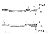
- Fig. 1 is a cross section through a first embodiment of the metallic cylinder head gasket according to the invention.
- Fig. 2 is a cross-sectional view of a second embodiment of the metallic cylinder head gasket according to the invention.
- a metallic gasket layer 2 designed as a functional layer is shown, which is provided in its region adjacent to the combustion chamber 14 with corresponding openings corresponding to the combustion chambers.
- the gasket layer has a full bead 5, which serves for the elastic sealing of the combustion chambers and encloses the openings.
- the gasket layer has a flat portion 3 which extends directly to the opening or to the combustion chamber. With the flat portion 3, a ring insert 4 is welded in radial overlap.
- the metallic ring insert 4 has a crank or half bead 11. The ring insert 4 is welded with its remote from the combustion chamber 14 area with the gasket layer 2.
- the stopper zone is radially reinforced and flexibilized.
- the crank or half bead 11 is formed in the ring insert 4.
- the bead 5 is axially adjacent to the flat portion 3.
- the flat portion 3 is almost completely covered by the ring liner 4.
- the gasket layer 2 is likewise designed as a functional layer and has in its region adjoining the combustion chamber 14 a ring insert 6 which has a bead 13 (full bead). having.
- the ring insert 6 is welded on both sides of the bead 13 with the flat portion 3 of the gasket layer 2.
- the bead 13 is a full bead, which locally increases the elasticity or sealing pressure in the stopper zone.
- the arrangement of the bead 5 and the flat portion 3 correspond to FIG. 1.
- the elasticity of the radially adjacent to the combustion chambers stopper region is increased in order to prevent a possible leak in pressure drop.
- the so-called "overblowing" of creeping gases is effectively avoided.
- the gasket layer 2 may also be formed as a planar spacer.
- the gasket layers 2 may additionally be provided with a bead, half bead or offset.
Landscapes
- Engineering & Computer Science (AREA)
- General Engineering & Computer Science (AREA)
- Mechanical Engineering (AREA)
- Gasket Seals (AREA)
Claims (4)
- Joint de culasse métallique présentant au moins une position de joint (2) avec des ouvertures en fonction des chambres de combustion (14) sur des moteurs à combustion interne, une partie (3) plate, qui est disposée tout autour des ouvertures et une moulure pleine (5), qui entoure les ouvertures à proximité de la partie (3) aplatie, la.position de joint (2) étant dotée d'une insertion annulaire (4, 6) dans sa zone tournée vers l'espace de combustion (14), afin de générer une zone d'étanchéité élastique sur le bord de l'espace de combustion (14), caractérisé en ce que l'insertion annulaire (4, 6) est reliée à la partie (3) plate et en ce que l'insertion annulaire (4, 6) présente une moulure (11, 13) dans le plan radial de la partie (3) plate.
- Joint de culasse métallique selon la revendication 1, caractérisé en ce que la moulure (11) est une demi-moulure.
- Joint de culasse métallique selon la revendication 1 ou 2, caractérisé en ce que l'insertion annulaire (4, 6, 8) est soudée avec la position de joint (2, 10).
- Joint de culasse métallique selon les revendications 2 à 3, caractérisé en ce que la moulure (13) est une moulure pleine.
Priority Applications (1)
| Application Number | Priority Date | Filing Date | Title |
|---|---|---|---|
| EP05024204A EP1621803B1 (fr) | 2000-07-24 | 2001-05-21 | Joint de culasse de cylindre |
Applications Claiming Priority (2)
| Application Number | Priority Date | Filing Date | Title |
|---|---|---|---|
| DE10035969 | 2000-07-24 | ||
| DE2000135969 DE10035969B4 (de) | 2000-07-24 | 2000-07-24 | Zylinderkopfdichtung mit elastischer Stopperlage |
Related Child Applications (1)
| Application Number | Title | Priority Date | Filing Date |
|---|---|---|---|
| EP05024204A Division EP1621803B1 (fr) | 2000-07-24 | 2001-05-21 | Joint de culasse de cylindre |
Publications (3)
| Publication Number | Publication Date |
|---|---|
| EP1176342A2 EP1176342A2 (fr) | 2002-01-30 |
| EP1176342A3 EP1176342A3 (fr) | 2005-05-25 |
| EP1176342B1 true EP1176342B1 (fr) | 2006-08-23 |
Family
ID=7650009
Family Applications (2)
| Application Number | Title | Priority Date | Filing Date |
|---|---|---|---|
| EP20010112402 Expired - Lifetime EP1176342B1 (fr) | 2000-07-24 | 2001-05-21 | Joint de culasse avec cale élastique |
| EP05024204A Expired - Lifetime EP1621803B1 (fr) | 2000-07-24 | 2001-05-21 | Joint de culasse de cylindre |
Family Applications After (1)
| Application Number | Title | Priority Date | Filing Date |
|---|---|---|---|
| EP05024204A Expired - Lifetime EP1621803B1 (fr) | 2000-07-24 | 2001-05-21 | Joint de culasse de cylindre |
Country Status (3)
| Country | Link |
|---|---|
| EP (2) | EP1176342B1 (fr) |
| DE (3) | DE10035969B4 (fr) |
| ES (2) | ES2293461T3 (fr) |
Families Citing this family (1)
| Publication number | Priority date | Publication date | Assignee | Title |
|---|---|---|---|---|
| JP2005226806A (ja) * | 2004-02-16 | 2005-08-25 | Ishikawa Gasket Co Ltd | シリンダヘッドガスケット |
Family Cites Families (21)
| Publication number | Priority date | Publication date | Assignee | Title |
|---|---|---|---|---|
| GB1370125A (en) * | 1971-04-27 | 1974-10-09 | Nicholson T P | Washers and gaskets |
| JPH0227714Y2 (fr) * | 1984-12-14 | 1990-07-26 | ||
| DE3809690A1 (de) * | 1988-03-23 | 1989-10-12 | Goetze Ag | Weichstoffflachdichtung |
| US5435575A (en) * | 1988-08-11 | 1995-07-25 | Ishikawa Gasket Co., Ltd. | Steel laminate gasket |
| US5560623A (en) * | 1990-04-04 | 1996-10-01 | Kabushiki Kaisha Ket And Ket | Metal gasket |
| JPH04191570A (ja) * | 1990-11-26 | 1992-07-09 | Ketsuto & Ketsuto:Kk | 金属ガスケット |
| JPH04347065A (ja) * | 1991-05-21 | 1992-12-02 | Japan Metal Gasket Co Ltd | 金属ガスケット |
| JPH086805B2 (ja) * | 1992-06-09 | 1996-01-29 | 日本メタルガスケット株式会社 | 金属ガスケット |
| JP3489755B2 (ja) * | 1994-08-05 | 2004-01-26 | 日本ガスケット株式会社 | 金属製ガスケット |
| DE4440503C1 (de) * | 1994-11-12 | 1996-03-28 | Payen Goetze Gmbh | Metallische Flachdichtung |
| EP0717218A1 (fr) * | 1994-12-16 | 1996-06-19 | Ishikawa Gasket Co. Ltd. | Joint flat métallique pourvu d'un anneau |
| FR2737255B1 (fr) * | 1995-07-26 | 1997-09-05 | Curty Payen Sa | Joint de culasse pour moteur a combustion interne |
| JP3230966B2 (ja) * | 1995-10-09 | 2001-11-19 | 日本ガスケット株式会社 | 金属製ガスケット |
| JPH09105462A (ja) * | 1995-10-09 | 1997-04-22 | Nippon Gasket Co Ltd | 金属製ガスケット |
| DE19548572C2 (de) * | 1995-12-23 | 1998-11-26 | Elringklinger Gmbh | Zylinderkopfdichtung |
| JP2929485B2 (ja) * | 1996-05-22 | 1999-08-03 | 石川ガスケット株式会社 | 金属積層形ガスケット |
| JP3343478B2 (ja) * | 1996-06-20 | 2002-11-11 | 日本ガスケット株式会社 | 金属製ガスケット |
| JPH10184916A (ja) * | 1996-12-20 | 1998-07-14 | Nippon Gasket Co Ltd | 金属製ガスケット |
| DE29912950U1 (de) * | 1999-07-24 | 2000-01-27 | Federal-Mogul Sealing Systems GmbH, 57562 Herdorf | Metallische Flachdichtung |
| FR2803893B1 (fr) * | 2000-01-17 | 2002-03-08 | Meillor Sa | Procede de realisation d'une cale dite stoppeur sur un joint, notamment sur un joint de culasse, et joint ainsi obtenu |
| DE10029352B4 (de) * | 2000-06-15 | 2007-01-04 | Reinz-Dichtungs-Gmbh & Co. Kg | Flachdichtung |
-
2000
- 2000-07-24 DE DE2000135969 patent/DE10035969B4/de not_active Expired - Fee Related
-
2001
- 2001-05-21 EP EP20010112402 patent/EP1176342B1/fr not_active Expired - Lifetime
- 2001-05-21 DE DE50113244T patent/DE50113244D1/de not_active Expired - Lifetime
- 2001-05-21 EP EP05024204A patent/EP1621803B1/fr not_active Expired - Lifetime
- 2001-05-21 DE DE50110789T patent/DE50110789D1/de not_active Expired - Lifetime
- 2001-05-21 ES ES05024204T patent/ES2293461T3/es not_active Expired - Lifetime
- 2001-05-21 ES ES01112402T patent/ES2270921T3/es not_active Expired - Lifetime
Also Published As
| Publication number | Publication date |
|---|---|
| ES2270921T3 (es) | 2007-04-16 |
| EP1621803B1 (fr) | 2007-11-07 |
| ES2293461T3 (es) | 2008-03-16 |
| EP1621803A1 (fr) | 2006-02-01 |
| EP1176342A2 (fr) | 2002-01-30 |
| DE50113244D1 (de) | 2007-12-20 |
| DE10035969B4 (de) | 2006-02-16 |
| EP1176342A3 (fr) | 2005-05-25 |
| DE10035969A1 (de) | 2002-02-21 |
| DE50110789D1 (de) | 2006-10-05 |
Similar Documents
| Publication | Publication Date | Title |
|---|---|---|
| DE102008042754B4 (de) | Metalldichtung | |
| EP0946836B1 (fr) | Joint plat metallique | |
| EP0740092B1 (fr) | Joint de culasse métallique | |
| DE19829656B4 (de) | Metalldichtung | |
| DE19634964B4 (de) | Metalldichtung | |
| DE69307780T2 (de) | Metalldichtung | |
| DE69527237T2 (de) | Flachdichtung aus Metall-Elastomer-Verbrudwerkstoff | |
| EP0877183B1 (fr) | Joint de culasse métallique | |
| EP1327799B1 (fr) | Joint de culasse pour la compensation de dépressions locales dans la zone du limiteur de compression | |
| EP3115656B1 (fr) | Joint plat | |
| DE69108877T2 (de) | Dichtung aus Schichtstahl. | |
| EP2430334B1 (fr) | Joint plat à nervure d'étanchéité et parte en creux ainsi que son procédé de production | |
| EP0829661A1 (fr) | Joint plat métallique | |
| DE602004003653T2 (de) | Metalldichtung | |
| EP1403572B1 (fr) | Joint de culasse à couches multiples | |
| DE3142344A1 (de) | Zylinderkopfdichtung | |
| DE19539245C2 (de) | Dichtungssystem für Brennkraftmaschinen zur Abdichtung eines Spaltes zwischen Zylinderkopf und Zylinderblech einer Brennkraftmaschine | |
| EP1176342B1 (fr) | Joint de culasse avec cale élastique | |
| DE3225420A1 (de) | Dichtungsanordnung und verfahren zu ihrer herstellung | |
| DE69003235T2 (de) | Laminierte Stahldichtung. | |
| DE60203119T2 (de) | Zylinderkopfdichtung mit einem rand-zu-rand-anschlagsring | |
| DE68913547T2 (de) | Stahllaminatdichtung. | |
| DE20019412U1 (de) | Zylinderkopfdichtung | |
| DE19523825A1 (de) | Metallische Flachdichtung | |
| DE102019217868B4 (de) | Metallisches Dichtungsbauteil mit Zwischenlagenzentrierung |
Legal Events
| Date | Code | Title | Description |
|---|---|---|---|
| PUAI | Public reference made under article 153(3) epc to a published international application that has entered the european phase |
Free format text: ORIGINAL CODE: 0009012 |
|
| AK | Designated contracting states |
Kind code of ref document: A2 Designated state(s): AT BE CH CY DE DK ES FI FR GB GR IE IT LI LU MC NL PT SE TR |
|
| AX | Request for extension of the european patent |
Free format text: AL;LT;LV;MK;RO;SI |
|
| PUAL | Search report despatched |
Free format text: ORIGINAL CODE: 0009013 |
|
| AK | Designated contracting states |
Kind code of ref document: A3 Designated state(s): AT BE CH CY DE DK ES FI FR GB GR IE IT LI LU MC NL PT SE TR |
|
| AX | Request for extension of the european patent |
Extension state: AL LT LV MK RO SI |
|
| 17P | Request for examination filed |
Effective date: 20050609 |
|
| GRAP | Despatch of communication of intention to grant a patent |
Free format text: ORIGINAL CODE: EPIDOSNIGR1 |
|
| AKX | Designation fees paid |
Designated state(s): DE ES FR GB IT |
|
| GRAS | Grant fee paid |
Free format text: ORIGINAL CODE: EPIDOSNIGR3 |
|
| GRAA | (expected) grant |
Free format text: ORIGINAL CODE: 0009210 |
|
| AK | Designated contracting states |
Kind code of ref document: B1 Designated state(s): DE ES FR GB IT |
|
| PG25 | Lapsed in a contracting state [announced via postgrant information from national office to epo] |
Ref country code: IT Free format text: LAPSE BECAUSE OF FAILURE TO SUBMIT A TRANSLATION OF THE DESCRIPTION OR TO PAY THE FEE WITHIN THE PRESCRIBED TIME-LIMIT;WARNING: LAPSES OF ITALIAN PATENTS WITH EFFECTIVE DATE BEFORE 2007 MAY HAVE OCCURRED AT ANY TIME BEFORE 2007. THE CORRECT EFFECTIVE DATE MAY BE DIFFERENT FROM THE ONE RECORDED. Effective date: 20060823 |
|
| REG | Reference to a national code |
Ref country code: GB Ref legal event code: FG4D Free format text: NOT ENGLISH |
|
| REF | Corresponds to: |
Ref document number: 50110789 Country of ref document: DE Date of ref document: 20061005 Kind code of ref document: P |
|
| GBT | Gb: translation of ep patent filed (gb section 77(6)(a)/1977) |
Effective date: 20061004 |
|
| ET | Fr: translation filed | ||
| REG | Reference to a national code |
Ref country code: ES Ref legal event code: FG2A Ref document number: 2270921 Country of ref document: ES Kind code of ref document: T3 |
|
| PLBE | No opposition filed within time limit |
Free format text: ORIGINAL CODE: 0009261 |
|
| STAA | Information on the status of an ep patent application or granted ep patent |
Free format text: STATUS: NO OPPOSITION FILED WITHIN TIME LIMIT |
|
| 26N | No opposition filed |
Effective date: 20070524 |
|
| PGFP | Annual fee paid to national office [announced via postgrant information from national office to epo] |
Ref country code: ES Payment date: 20080513 Year of fee payment: 8 |
|
| PGFP | Annual fee paid to national office [announced via postgrant information from national office to epo] |
Ref country code: GB Payment date: 20080407 Year of fee payment: 8 |
|
| GBPC | Gb: european patent ceased through non-payment of renewal fee |
Effective date: 20090521 |
|
| PG25 | Lapsed in a contracting state [announced via postgrant information from national office to epo] |
Ref country code: GB Free format text: LAPSE BECAUSE OF NON-PAYMENT OF DUE FEES Effective date: 20090521 |
|
| REG | Reference to a national code |
Ref country code: ES Ref legal event code: FD2A Effective date: 20090522 |
|
| PG25 | Lapsed in a contracting state [announced via postgrant information from national office to epo] |
Ref country code: ES Free format text: LAPSE BECAUSE OF NON-PAYMENT OF DUE FEES Effective date: 20090522 |
|
| PGFP | Annual fee paid to national office [announced via postgrant information from national office to epo] |
Ref country code: DE Payment date: 20130531 Year of fee payment: 13 |
|
| PGFP | Annual fee paid to national office [announced via postgrant information from national office to epo] |
Ref country code: IT Payment date: 20130521 Year of fee payment: 13 Ref country code: FR Payment date: 20130531 Year of fee payment: 13 |
|
| REG | Reference to a national code |
Ref country code: DE Ref legal event code: R119 Ref document number: 50110789 Country of ref document: DE |
|
| REG | Reference to a national code |
Ref country code: FR Ref legal event code: ST Effective date: 20150130 |
|
| REG | Reference to a national code |
Ref country code: DE Ref legal event code: R119 Ref document number: 50110789 Country of ref document: DE Effective date: 20141202 |
|
| PG25 | Lapsed in a contracting state [announced via postgrant information from national office to epo] |
Ref country code: IT Free format text: LAPSE BECAUSE OF NON-PAYMENT OF DUE FEES Effective date: 20140521 Ref country code: DE Free format text: LAPSE BECAUSE OF NON-PAYMENT OF DUE FEES Effective date: 20141202 |
|
| PG25 | Lapsed in a contracting state [announced via postgrant information from national office to epo] |
Ref country code: FR Free format text: LAPSE BECAUSE OF NON-PAYMENT OF DUE FEES Effective date: 20140602 |