EP1176402A1 - Dosiervorrichtung und Spender mit einer solchen Vorrichtung - Google Patents
Dosiervorrichtung und Spender mit einer solchen Vorrichtung Download PDFInfo
- Publication number
- EP1176402A1 EP1176402A1 EP00202686A EP00202686A EP1176402A1 EP 1176402 A1 EP1176402 A1 EP 1176402A1 EP 00202686 A EP00202686 A EP 00202686A EP 00202686 A EP00202686 A EP 00202686A EP 1176402 A1 EP1176402 A1 EP 1176402A1
- Authority
- EP
- European Patent Office
- Prior art keywords
- powder
- hopper
- opening
- shutter
- dosing
- Prior art date
- Legal status (The legal status is an assumption and is not a legal conclusion. Google has not performed a legal analysis and makes no representation as to the accuracy of the status listed.)
- Withdrawn
Links
- 239000000843 powder Substances 0.000 claims abstract description 57
- 235000013361 beverage Nutrition 0.000 claims description 11
- 230000005540 biological transmission Effects 0.000 claims description 11
- 238000002360 preparation method Methods 0.000 claims description 11
- 238000009826 distribution Methods 0.000 claims description 10
- 239000000203 mixture Substances 0.000 claims description 10
- 230000004913 activation Effects 0.000 claims description 7
- 230000009849 deactivation Effects 0.000 claims description 6
- 238000003860 storage Methods 0.000 claims description 6
- 235000013305 food Nutrition 0.000 claims description 4
- 238000007789 sealing Methods 0.000 claims description 4
- 230000007420 reactivation Effects 0.000 claims description 2
- 235000013353 coffee beverage Nutrition 0.000 abstract description 6
- 235000013336 milk Nutrition 0.000 abstract description 5
- 239000008267 milk Substances 0.000 abstract description 5
- 210000004080 milk Anatomy 0.000 abstract description 5
- 230000008901 benefit Effects 0.000 description 8
- XLYOFNOQVPJJNP-UHFFFAOYSA-N water Substances O XLYOFNOQVPJJNP-UHFFFAOYSA-N 0.000 description 4
- 238000004140 cleaning Methods 0.000 description 3
- 230000001276 controlling effect Effects 0.000 description 2
- 230000000694 effects Effects 0.000 description 2
- 238000000605 extraction Methods 0.000 description 2
- 238000010438 heat treatment Methods 0.000 description 2
- 235000012171 hot beverage Nutrition 0.000 description 2
- 235000021539 instant coffee Nutrition 0.000 description 2
- MFRCZYUUKMFJQJ-UHFFFAOYSA-N 1,4-dioxane-2,5-dione;1,3-dioxan-2-one Chemical compound O=C1OCCCO1.O=C1COC(=O)CO1 MFRCZYUUKMFJQJ-UHFFFAOYSA-N 0.000 description 1
- 241001080024 Telles Species 0.000 description 1
- 230000003213 activating effect Effects 0.000 description 1
- 238000005054 agglomeration Methods 0.000 description 1
- 230000002776 aggregation Effects 0.000 description 1
- 230000004888 barrier function Effects 0.000 description 1
- 235000015116 cappuccino Nutrition 0.000 description 1
- 230000015556 catabolic process Effects 0.000 description 1
- 238000011109 contamination Methods 0.000 description 1
- 230000008878 coupling Effects 0.000 description 1
- 238000010168 coupling process Methods 0.000 description 1
- 238000005859 coupling reaction Methods 0.000 description 1
- 238000006731 degradation reaction Methods 0.000 description 1
- 230000005484 gravity Effects 0.000 description 1
- 238000009434 installation Methods 0.000 description 1
- 239000007788 liquid Substances 0.000 description 1
- 238000012423 maintenance Methods 0.000 description 1
- 238000004519 manufacturing process Methods 0.000 description 1
- 238000005457 optimization Methods 0.000 description 1
- 210000000056 organ Anatomy 0.000 description 1
- 230000009467 reduction Effects 0.000 description 1
- 230000001105 regulatory effect Effects 0.000 description 1
- 238000007790 scraping Methods 0.000 description 1
- 238000010008 shearing Methods 0.000 description 1
- 239000007787 solid Substances 0.000 description 1
Images




Classifications
-
- G—PHYSICS
- G01—MEASURING; TESTING
- G01F—MEASURING VOLUME, VOLUME FLOW, MASS FLOW OR LIQUID LEVEL; METERING BY VOLUME
- G01F13/00—Apparatus for measuring by volume and delivering fluids or fluent solid materials, not provided for in the preceding groups
- G01F13/001—Apparatus for measuring by volume and delivering fluids or fluent solid materials, not provided for in the preceding groups for fluent solid material
- G01F13/005—Apparatus for measuring by volume and delivering fluids or fluent solid materials, not provided for in the preceding groups for fluent solid material comprising a screw conveyor
-
- A—HUMAN NECESSITIES
- A47—FURNITURE; DOMESTIC ARTICLES OR APPLIANCES; COFFEE MILLS; SPICE MILLS; SUCTION CLEANERS IN GENERAL
- A47J—KITCHEN EQUIPMENT; COFFEE MILLS; SPICE MILLS; APPARATUS FOR MAKING BEVERAGES
- A47J31/00—Apparatus for making beverages
- A47J31/40—Beverage-making apparatus with dispensing means for adding a measured quantity of ingredients, e.g. coffee, water, sugar, cocoa, milk, tea
- A47J31/404—Powder dosing devices
-
- G—PHYSICS
- G01—MEASURING; TESTING
- G01F—MEASURING VOLUME, VOLUME FLOW, MASS FLOW OR LIQUID LEVEL; METERING BY VOLUME
- G01F11/00—Apparatus requiring external operation adapted at each repeated and identical operation to measure and separate a predetermined volume of fluid or fluent solid material from a supply or container, without regard to weight, and to deliver it
- G01F11/28—Apparatus requiring external operation adapted at each repeated and identical operation to measure and separate a predetermined volume of fluid or fluent solid material from a supply or container, without regard to weight, and to deliver it with stationary measuring chambers having constant volume during measurement
- G01F11/42—Apparatus requiring external operation adapted at each repeated and identical operation to measure and separate a predetermined volume of fluid or fluent solid material from a supply or container, without regard to weight, and to deliver it with stationary measuring chambers having constant volume during measurement with supply or discharge valves of the rotary or oscillatory type
- G01F11/46—Apparatus requiring external operation adapted at each repeated and identical operation to measure and separate a predetermined volume of fluid or fluent solid material from a supply or container, without regard to weight, and to deliver it with stationary measuring chambers having constant volume during measurement with supply or discharge valves of the rotary or oscillatory type for fluent solid material
Definitions
- the invention relates to the field of apparatus for automatic distribution of drinks on request. More in particular, the invention relates to devices intended to equip the catering services of means of transport such as planes, trains or other.
- vending machines for drinks using powder-based products in the premises public.
- These distributors are generally fairly large capacity devices.
- Such devices include containers for storing powder, hoppers downstream of containers fitted with means of dosing and mixing bowls downstream of the hoppers for collect the powder and mix with a quantity water then distribute by gravity at through distribution tubes.
- the powder is expelled from the dosing device into the mixing bowl by means of a dosing screw through an area opening of the hopper.
- the quantity dosed is a function the number of revolutions operated by the dosing screw.
- this principle is applied to distributors of small dimensions, there are problems of regularity of the quantity of powder dosed as well as fouling problems with the mixing bowl and pipes. These problems appear to be due to there is always a little powder left on the edge of the opening zone after stopping the dosing means. A at least part of this powder tends to fall in the bowl outside the preparation cycles; what fouls the bowl by forming lumps or lumps poorly soluble.
- Another part of the powder has tendency to agglomerate at the opening of the metering device by forming barbs which are made wet and sticky by water vapor from the mixing bowl. These problems are exacerbated when using very hygroscopic powders like milk powder. Regular cleaning of the device is thus made compulsory in order to avoid any risk of contamination.
- the present invention therefore aims to solve these problems by proposing a dosing device which can be used in a beverage dispensing device; in particular, even if not exclusively, for a application to a compact distributor designed to equip self-service airliners or other means of transportation.
- the present invention relates to a device dosing of powder-based food product
- a device dosing of powder-based food product including a hopper for storing the powder, a dosing means located in the hopper in order to transport the hopper powder to an area feed comprising a base portion provided with a opening allowing a metered amount of powder; characterized in that a closure element is arranged with the base portion to allow closing the opening of the base portion and what the device includes control means able to control the shutter of the element shutter from the stop of the dosing means.
- such a device solves the problems with falling powder outside the cycle preparation of the drink in the mixing bowl and thus avoids problems due to fouling mixing bowl (s) and tube (s) distribution.
- the basic portion forms a portion of tube provided with an opening allowing the fall of a metered amount of powder and the sealing element is arranged in coaxial relationship with the base portion so allow the opening to be closed by rotation of the closure element around the base portion.
- a such an arrangement has the advantage of eliminating, by effect of scraping of the sealing element, burrs and barbs powder that can agglomerate on the edges of the opening. The opening therefore remains perfectly clean after each dosing cycle.
- the closure element has also the shape of a portion of tube having a light; the closure element being movable by sliding in rotation around the base portion between an open position in which the light from the closure element is at least partly coincident with the opening and a closed position in which the light from the shutter element is moved completely outside the opening field.
- the shutter element which thus completely closes the opening plays the role of vapor barrier avoiding the powder in the hopper to absorb moisture from the bowl.
- the means for controlling the closure element include at least one drive member such as electric motor.
- a drive member such as electric motor.
- the movement of the closure element is controlled by a rear drive hopper by means of a transmission system comprising transmission means of which at least one transmission rod and at least one gear means in relationship with said rod and the closure element.
- the invention also relates to a device for distribution allowing the preparation of drinks according to a choice of combinations from at least two sources of powder and having the particularity of being able to be inserted in a reduced space such as in the cabinet of an airplane catering compartment of line or the like.
- the advantage of such a configuration is that it can have a compact device that is nevertheless capable of prepare a large number of drinks according to a choice multiple like for example the preparation of drinks hot with soluble coffee and / or milk.
- the beverage dispensing device on request includes at least one hopper, a housing located at above the hopper characterized in that the hopper includes guide means adapted to receive a powder refill element housing as well as guide means being arranged so as to allow the engagement of said recharging element according to a substantially horizontal direction.
- the refill element has the form of a tray having its opening towards the hopper during its commitment.
- Such a feeding device is facilitate powder feeding. Food can so be done by the front of the machine simply by opening of the front panel of the device.
- Such a system has an advantage over a system supply by filling a container which requires lifting the top panel of the machine or at least the removal of the container to perform filling. This reduces the risk of doing fall off the powder outside the storage container.
- the machine can be carried out compactly, so therefore be easily built into a catering area while authorizing a powder reloading of the device that is fast and without difficulty special.
- the device preferably uses elements of refills such as those described in the patent application European number 1028068 filed on 12.02.1999 including content is fully incorporated by reference to the this request.
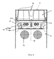
- the dispensing device 1 shown in FIG. 1 as a preferred illustration, is a distribution of hot beverages of the coffee type which can be installed in a confined space, in particular can be built into a space 8 dimensions standard, as in that of a catering cabinet an airliner, for example, in a self-service area.
- the device comprises a cabinet 10 forming the walls of the device which delimit an internal chamber 7, an open distribution area 11 to allow engaging a container such as a cup, a front panel 12 with preset buttons 120 and a 121 locking system secured according to standards in force of civil aviation.
- the panel has the characteristic of being able to open on the front, preferably along an axis of rotation located on one of the edges of the panel. In this case, the panel opens pulling from top to bottom along an axis of rotation 122 located at the lower base of the panel (fig. 4).
- Figs. 2 to 10 illustrate the preferred mode of the device dispenser comprising two metering systems 20, 21 inserted in parallel in the device.
- a device for distribution for aircraft with two metering systems has the advantage of allowing the preparation of hot drinks based on several combinations possible from two different types of powder, usually based on soluble coffee powder and / or milk.
- Each device therefore includes a hopper 22 of horizontal shape substantially rectangular which has a metering means 23 oriented longitudinally and located at the bottom of the hopper.
- the dosing means 23 is preferably a screw endless dosing known from the state of the art which is driven by a drive, preferably a electric motor 53 located at the rear of the hopper (visible in fig. 5).
- the hopper is supplied with powder by means of a powder refill element 2 in shape of tray with its opening in direction hopper and edges 200 extending around the perimeter of its opening, as further described more in detail in patent application EP-A-1028068.
- Charging element 2 can be inserted in one direction substantially horizontal after opening the front panel 12 between filling elements 90 forming a housing 91 of the device.
- the hopper has the means guide 24 and stop 241 intended to cooperate with the edges 200 of the recharging element and allowing the charging element 2 to be brought into position overturned above the hopper to partially pour in at least its contents and serve as a storage container.
- Such a configuration of engagement in the device has the advantage of allowing, at the same time, a replenishment of the device from the front; that is to say, by opening the front panel 12 and, a optimization of the storage space in the machine with minimum dead volume.
- the size of room 7 can therefore be best optimized according to capacity desired and depending on the installation standards to respect.
- the recharging elements are intended to be held in place above the hoppers by means stop 240, for example, a lever having a part engagement intended to cooperate with the leading edge of the charging element, the lever being mounted on one guide parts 24 of the hopper.
- the powder stored in the hopper is transported by the dosing means or dosing screw 23 to an area 25 located at the front and in the extension of the dosage means.
- each hopper has an asymmetrical longitudinal shape with respect to its median longitudinal plane P. More in particular, the hopper has walls converging to direct the mass of powder along the dosing means according to the supply line.
- the walls include an outer wall of slight slope 40 and an inner wall 41 of steeper slope. The walls meet below the dosing screw by a line of rounded connection according to the profile of the screw.
- the two hoppers 22a, 22b are arranged in the device distribution symmetrically to the axis median Po of the device. It results from such configuration, that the hopper feed areas are close to each other near the axis median Po.
- the approximation of the feeding zones allows the use of a single mixing bowl 6 appropriately sized to receive the powder of the two metering devices as shown in fig. 3. It is important to note that the approximation of the zones allows a lower dimensioning of the bowl 6 in all its dimensions; because of its more narrow width due to the approximation of the zones, the slope necessary for a satisfactory flow of the mixture powder-liquid in the mixing bowl remains sufficient to allow for a relatively low height of the bowl. It should also be noted that the approximation of the zones feeding each other obtained by asymmetry of hoppers avoids the use of channels converging called "falls" at the exit of the hopper which are oriented towards the bowl. It is a advantage insofar as these "falls" tend to easily clog.
- the feeding zone 25 is formed by a portion of base 26 protruding outside the hopper as the more particularly shows fig. 7.
- the portion of base 26 has a tubular shape and is provided with a opening 27 in the shape of a portion of an arcuate quadrilateral which interrupts the tubular portion on its periphery.
- the opening is preferably directed downwards to allow the powder to fall towards the bowl of mixture 6 (Fig. 3).
- a sealing element 28 is arranged around the base portion 26 in order to allow selective closing of the opening 27.
- the closure element is preferably a portion of tube of larger diameter and is arranged coaxially with the base portion.
- the shutter member 28 has a lumen 29 extending over an arcuate portion relative to the tube portion.
- the lumen 29 preferably has a shape substantially identical to that of the opening 27 as well as substantially identical or slightly larger dimensions favoring the shearing in order to eliminate, at the end of each cycle, the barbs which may have formed along the edges. of the opening.
- a fixed cover 30 for closing the front of the feed zone is provided which is inserted into the bore of the base portion 26 and which is prevented from rotating by lips 30a, 30b substantially projecting delimiting the edges d 'an opening 31 of substantially the same configuration as the opening 27 with which it coincides in fixing.
- the cover / shutter element assembly is mounted coaxially in sliding along axis I and can be easily dislodged allowing complete cleaning of the supply area.
- the shutter element 28 is controlled by gear means 32, 35, 36 connected to a transmission rod 37, itself connected to a control member 38. More specifically, the shutter element 28 has , at its base, a cylindrical gear portion 32 interrupted by an arcuate guiding zone 33 for guiding a stop element 34 secured to the front of the hopper.
- the gear portion 32 is connected to a pair of gears 35, 36 axially offset with respect to the feed axis and integral with the hopper making it possible to shift the control of the movement of the shutter element to the side outside of the hopper corresponding to the side with the lowest slope of the hopper and therefore with greater clearance for housing a transmission rod 37.
- the transmission rod 37 is thus located under the outer wall 40 of the hopper and is connected to the gear 36 located in the extension of the rod and offset laterally with respect to an intermediate gear 35.
- the control member 38 is an electric motor, preferably a miniature DC motor of the type of those produced by the company Maxon Motor Ag. Of the type 16 EBCLL 2W SL 1WE with a voltage of 1 to 24 VDC.
- the principle of opening / closing the element of the metering device is illustrated by the figures 8 to 10.
- the element shutter 28 is in the closed position such that fig. 10. Part of the tube portion of the element shutter completely covers the light 27 of the underlying base portion.
- the electrical signal is sent to a control system (not shown) which triggers, first, the opening of the element shutter 28 by activating the control member or motor 38 controlling the opening of the organ shutter.
- a control system clock allows set the activation time of the control unit until the end of the opening.
- Figure 9 shows a intermediate opening position of the element shutter.
- the opening adjustment is made from precisely by means of the stop member 34 which cooperates as far as it will go at one end of the guide 33 defined as the open position of the Fig. 8. This position is when the light 29 of the closure element substantially coincides with opening 27 of the base portion.
- the engine is then disabled.
- the control system then activates the motor 53 of the metering means for a time necessary by means of the clock which is a function of the quantity to be dosed by the dosage means.
- the feeding area is open as in fig. 8.
- the control system deactivates the dosing means by switching off its motor 53.
- control system activates the motor again 38, the polarity of which reverses, which controls the rotation of the closure element in the opposite direction.
- the stop element 34 adjusts the closing position in serving as a limit stop against the end opposite of the guide zone 33. In the closed position, the dosing device is ready for a new cycle (Fig. 10).
- the metering 20, 21 are mounted in the chamber 7 so easily removable to facilitate maintenance as well as regular cleaning of the elements in contact with food products. So the two hoppers 22a, 22b are mounted together on a removable drawer 50 tray-shaped allowing the hoppers to rest in parallel on the main surface of the drawer. The drawer is held in place in the chamber by elements of guide 51, 52 connected to each side wall 70, 71 of the room. Removable connection means drawer 50 relative to the chamber are provided for keep the drawer in place without risk of movement possible accidents (not shown).
- the motors 38 are preferably made integral with chamber 7 and include means for connection 39 which make them pluggable by means of transmission when installing the drawer like the shows fig. 4. More specifically, the means of plug-in connections form a subset coupling comprising a solid 390 socket of the transmission rod 37 in which cooperates removably a male socket 391, integral with the motor 38.
- the engine is also made integral with the side walls of the internal chamber 7 by means screws, rivets or equivalent type 380.
- connection of motors 53 can be done by means of connection such as a pair of gears 54 located at the rear of the hoppers 22a, 22b.
- a first gear 54a is integral metering means while a second gear 54b is coupled to the engine by a subset of reduction (not shown).
- the gear 54a is sets up alongside the gear 54b.
- Fig. 5 also shows the presence of control means of the powder level comprising sensors 56 of the type capacitive disposed between the two hoppers 22a, 22b and connected to the control system.
- control means of the powder level comprising sensors 56 of the type capacitive disposed between the two hoppers 22a, 22b and connected to the control system.
- a signal is sent by the sensor to the control system which activates the lighting of an individual or common diode to both sensors, on the front panel of the device.
- the operator is thus warned that at least one of the recharging elements is to be replaced. Replacement is done simply by opening the panel, then lifting lever 240, removing the empty refill element and engaging a new full refill in a horizontal movement of sliding along the guide means 24 up to stop means 241, then closing the panel.
- the device of the invention as illustrated in FIG. 1 is likely to meet dimensional standards and highly regulated electrics requiring approval certification bodies (CAA, JAA or FAA).
- CAA approval certification bodies
- the device of the invention is capable of meet the following dimensions: 6.3 inch width (160 mm), height of 12.0 inch (305 mm), depth of 15.28 inch (388 mm).
- the power supply of device for such an application is suitable for receive an alternating current of 115/200 Volts, three phases, 400 Hz.
- Standard connectors of the type CA3106R16S-1PF80 are installed allowing plugging in of the device on the power supply system of a cabinet properly equipped.
- a low voltage current circuit continuous (5, 12 and / or 24 Volts) for the operation of the motors, is provided in the device by means of a specific transformer to transform the main input current in low voltage current in the circuit.
- a water heater is also provided in the kettle type device with body resistive heating or thermoblock type or others, able to operate on the basis of the main current input so as to have heating power sufficient.
Landscapes
- Physics & Mathematics (AREA)
- Fluid Mechanics (AREA)
- General Physics & Mathematics (AREA)
- Engineering & Computer Science (AREA)
- Food Science & Technology (AREA)
- Apparatus For Making Beverages (AREA)
- Devices For Dispensing Beverages (AREA)
- Filling Or Emptying Of Bunkers, Hoppers, And Tanks (AREA)
- Accessories For Mixers (AREA)
- Beverage Vending Machines With Cups, And Gas Or Electricity Vending Machines (AREA)
Priority Applications (3)
| Application Number | Priority Date | Filing Date | Title |
|---|---|---|---|
| EP00202686A EP1176402A1 (de) | 2000-07-28 | 2000-07-28 | Dosiervorrichtung und Spender mit einer solchen Vorrichtung |
| US09/902,521 US6550648B2 (en) | 2000-07-28 | 2001-07-10 | Metering device and dispenser comprising such a device |
| JP2001225262A JP4814443B2 (ja) | 2000-07-28 | 2001-07-26 | 計量装置およびそのような装置を備えたディスペンサ |
Applications Claiming Priority (1)
| Application Number | Priority Date | Filing Date | Title |
|---|---|---|---|
| EP00202686A EP1176402A1 (de) | 2000-07-28 | 2000-07-28 | Dosiervorrichtung und Spender mit einer solchen Vorrichtung |
Publications (1)
| Publication Number | Publication Date |
|---|---|
| EP1176402A1 true EP1176402A1 (de) | 2002-01-30 |
Family
ID=8171864
Family Applications (1)
| Application Number | Title | Priority Date | Filing Date |
|---|---|---|---|
| EP00202686A Withdrawn EP1176402A1 (de) | 2000-07-28 | 2000-07-28 | Dosiervorrichtung und Spender mit einer solchen Vorrichtung |
Country Status (3)
| Country | Link |
|---|---|
| US (1) | US6550648B2 (de) |
| EP (1) | EP1176402A1 (de) |
| JP (1) | JP4814443B2 (de) |
Cited By (7)
| Publication number | Priority date | Publication date | Assignee | Title |
|---|---|---|---|---|
| WO2008029431A3 (en) * | 2006-09-08 | 2008-10-16 | Saeco Ipr Ltd | Dispensing device for loose products for the preparation of beverages, and machine containing said dispensing de vice |
| WO2009098563A1 (en) * | 2008-02-04 | 2009-08-13 | N & W Global Vending S.P.A. | Soluble-material container for a beverage vending machine |
| WO2013014040A1 (en) * | 2011-07-28 | 2013-01-31 | Nestec S.A. | Beverage dispenser with automatic closure of the powder containers chutes |
| ITVI20110221A1 (it) * | 2011-08-03 | 2013-02-04 | Fas Internat S P A | Sistema di alimentazione del prodotto di base da montare su macchine erogatrici di caffe' e su altri distributori di beveraggio con polveri solubili e non solubili. |
| CN104207656A (zh) * | 2013-06-01 | 2014-12-17 | 姜俊凭 | 食品搅动装置 |
| WO2016091830A1 (en) * | 2014-12-09 | 2016-06-16 | Nestec S.A. | Beverage dispenser with powder container |
| CN109008648A (zh) * | 2018-10-29 | 2018-12-18 | 贵港市厚顺信息技术有限公司 | 一种可退料的定量和多种混合装置 |
Families Citing this family (23)
| Publication number | Priority date | Publication date | Assignee | Title |
|---|---|---|---|---|
| US7799371B2 (en) * | 2005-11-17 | 2010-09-21 | Palo Alto Research Center Incorporated | Extruding/dispensing multiple materials to form high-aspect ratio extruded structures |
| US7912579B2 (en) * | 2007-01-10 | 2011-03-22 | Crane Merchandising Systems | Automatic cup detection and associated customer interface for vending apparatus and method therefor |
| ATE464818T1 (de) * | 2007-02-08 | 2010-05-15 | Wmf Wuerttemberg Metallwaren | Kaffeemaschine |
| ES2437868T3 (es) * | 2007-08-09 | 2014-01-14 | Nestec S.A. | Dispositivo de pieza única para almacenar, dosificar y mezclar una materia en polvo con un diluyente |
| USD647355S1 (en) * | 2008-05-16 | 2011-10-25 | The Coca-Cola Company | Beverage dispenser |
| USD644472S1 (en) * | 2008-05-16 | 2011-09-06 | The Coca-Cola Company | Beverage dispenser |
| IT1393039B1 (it) | 2009-02-09 | 2012-04-11 | Saeco Ipr Ltd | "macchina automatica per la produzione di caffe' con sensore per il rilevamento della quantita' di caffe' nella macchina" |
| EP2430954A1 (de) * | 2010-09-21 | 2012-03-21 | Nestec S.A. | Spender zur Herstellung von Getränken aus Pulver |
| JP2012115574A (ja) * | 2010-12-02 | 2012-06-21 | Hoshizaki Electric Co Ltd | 飲料ディスペンサ |
| CN202355204U (zh) * | 2011-10-22 | 2012-08-01 | 徐学渊 | 一种自动奶粉冲泡机 |
| CN105813510B (zh) * | 2013-12-20 | 2019-05-10 | 雀巢产品技术援助有限公司 | 具有粉末容器的饮料分配器 |
| CN103989406B (zh) * | 2014-06-09 | 2016-02-17 | 陈兆坚 | 奶粉定量器 |
| US20210401220A1 (en) * | 2016-01-14 | 2021-12-30 | Smiics Gmbh | Device for metering and/or for preparing a medium to be prepared, container for receiving and metering a component, container for receiving and metering fluid, and corresponding system |
| US11419451B2 (en) * | 2016-08-08 | 2022-08-23 | Plant Tap, LLC | Apparatus and method for producing beverages from dry ingredients |
| US11219329B2 (en) | 2018-04-12 | 2022-01-11 | Marmon Foodservice Technologies, Inc. | Sugar dispenser with auger |
| WO2019217932A1 (en) | 2018-05-11 | 2019-11-14 | Plant Tap, LLC | Food and beverage product |
| US11547975B2 (en) | 2019-02-07 | 2023-01-10 | Plant Tap, Inc. | System and method for dispensing a beverage |
| US11547134B2 (en) | 2019-03-21 | 2023-01-10 | Plant Tap, Inc. | Food and beverage product |
| US12209007B2 (en) | 2019-05-10 | 2025-01-28 | Plant Tap, LLC | System and method for dispensing a food and beverage product |
| US12297023B2 (en) | 2019-05-10 | 2025-05-13 | Plant Tap, LLC | System and method for dispensing a food and beverage product |
| IT202000002281A1 (it) * | 2020-02-05 | 2020-05-05 | Hero Europe S R L | Dispositivo per erogare e dosare materiali in polvere o pastosi o liquidi |
| JP2024541297A (ja) * | 2021-11-04 | 2024-11-08 | マシューズ インターナショナル ゲーエムベーハー | 乾式電極カレンダのニップへの粉末電極前駆体材料を重力によって引き起こされる供給のための粉末ホッパ、対応するアセンブリ、及び対応する方法 |
| US12163818B2 (en) * | 2022-06-09 | 2024-12-10 | Altria Client Services Llc | Apparatuses and methods for dosing loose material |
Citations (6)
| Publication number | Priority date | Publication date | Assignee | Title |
|---|---|---|---|---|
| GB2257129A (en) * | 1991-04-12 | 1993-01-06 | T F Holdings Limited | Particulate material supply. |
| US5241898A (en) | 1992-09-25 | 1993-09-07 | Grindmaster Corporation | Coffee dispenser and brewer apparatus |
| US5495962A (en) | 1993-11-11 | 1996-03-05 | Kabushiki Kaisha N-Tec | Constant quantity discharging device for powdered object |
| DE19519682A1 (de) | 1995-05-30 | 1996-12-05 | Bosch Gmbh Robert | Dosiervorrichtung |
| US6091920A (en) * | 1998-03-27 | 2000-07-18 | Minolta Co., Ltd. | Cylindrical toner container having a toner port and a movable lid for closing the toner port |
| EP1028068A1 (de) | 1999-02-12 | 2000-08-16 | Societe Des Produits Nestle S.A. | Nachfüllkartusche für eine Getränke-Abgabevorrichtung und an solche Kartuschen angepasste Vorrichtung |
Family Cites Families (10)
| Publication number | Priority date | Publication date | Assignee | Title |
|---|---|---|---|---|
| JPH04300510A (ja) * | 1991-03-28 | 1992-10-23 | Matsushita Refrig Co Ltd | 自動給茶機の茶葉供給装置 |
| DE4137324C1 (de) * | 1991-11-13 | 1993-02-04 | Cis Elektrogeraete Ag, Hinwil, Ch | |
| JP2566980Y2 (ja) * | 1992-09-04 | 1998-03-30 | 三洋電機株式会社 | コーヒサーバ |
| JPH07143932A (ja) * | 1993-11-24 | 1995-06-06 | Sharp Corp | 飲料抽出装置 |
| JPH08160727A (ja) * | 1994-12-05 | 1996-06-21 | Mita Ind Co Ltd | 画像形成装置のトナーカートリッジ装着機構 |
| US5503628A (en) * | 1995-03-15 | 1996-04-02 | Jettek, Inc. | Patient-fillable hypodermic jet injector |
| JPH09106156A (ja) * | 1995-10-09 | 1997-04-22 | Canon Inc | 現像剤容器、袋状シート及び現像剤充填装置 |
| JP3120723B2 (ja) * | 1996-03-13 | 2000-12-25 | 松下電器産業株式会社 | トナー容器及びこれを用いた複写機 |
| JP3090620B2 (ja) * | 1996-08-08 | 2000-09-25 | シーケーディ株式会社 | 小形粉末吐出装置 |
| JPH1097679A (ja) * | 1996-09-20 | 1998-04-14 | U C C Ueshima Cafe Kk | 自動販売機 |
-
2000
- 2000-07-28 EP EP00202686A patent/EP1176402A1/de not_active Withdrawn
-
2001
- 2001-07-10 US US09/902,521 patent/US6550648B2/en not_active Expired - Lifetime
- 2001-07-26 JP JP2001225262A patent/JP4814443B2/ja not_active Expired - Fee Related
Patent Citations (7)
| Publication number | Priority date | Publication date | Assignee | Title |
|---|---|---|---|---|
| GB2257129A (en) * | 1991-04-12 | 1993-01-06 | T F Holdings Limited | Particulate material supply. |
| US5241898A (en) | 1992-09-25 | 1993-09-07 | Grindmaster Corporation | Coffee dispenser and brewer apparatus |
| US5241898B1 (en) | 1992-09-25 | 1999-02-09 | Grindmaster Corp | Coffee dispenser and brewer apparatus |
| US5495962A (en) | 1993-11-11 | 1996-03-05 | Kabushiki Kaisha N-Tec | Constant quantity discharging device for powdered object |
| DE19519682A1 (de) | 1995-05-30 | 1996-12-05 | Bosch Gmbh Robert | Dosiervorrichtung |
| US6091920A (en) * | 1998-03-27 | 2000-07-18 | Minolta Co., Ltd. | Cylindrical toner container having a toner port and a movable lid for closing the toner port |
| EP1028068A1 (de) | 1999-02-12 | 2000-08-16 | Societe Des Produits Nestle S.A. | Nachfüllkartusche für eine Getränke-Abgabevorrichtung und an solche Kartuschen angepasste Vorrichtung |
Cited By (10)
| Publication number | Priority date | Publication date | Assignee | Title |
|---|---|---|---|---|
| WO2008029431A3 (en) * | 2006-09-08 | 2008-10-16 | Saeco Ipr Ltd | Dispensing device for loose products for the preparation of beverages, and machine containing said dispensing de vice |
| WO2009098563A1 (en) * | 2008-02-04 | 2009-08-13 | N & W Global Vending S.P.A. | Soluble-material container for a beverage vending machine |
| CN102026567A (zh) * | 2008-02-04 | 2011-04-20 | N&W全球销售股份公司 | 饮料自动售卖机的可溶材料容器 |
| WO2013014040A1 (en) * | 2011-07-28 | 2013-01-31 | Nestec S.A. | Beverage dispenser with automatic closure of the powder containers chutes |
| JP2014527944A (ja) * | 2011-07-28 | 2014-10-23 | ネステク ソシエテ アノニム | 粉末容器のシュートを自動的に閉鎖する飲料ディスペンサ |
| RU2598575C2 (ru) * | 2011-07-28 | 2016-09-27 | Нестек С.А. | Дозатор напитков с автоматическим закрытием выпускных клапанов контейнеров с порошкообразным ингредиентом |
| ITVI20110221A1 (it) * | 2011-08-03 | 2013-02-04 | Fas Internat S P A | Sistema di alimentazione del prodotto di base da montare su macchine erogatrici di caffe' e su altri distributori di beveraggio con polveri solubili e non solubili. |
| CN104207656A (zh) * | 2013-06-01 | 2014-12-17 | 姜俊凭 | 食品搅动装置 |
| WO2016091830A1 (en) * | 2014-12-09 | 2016-06-16 | Nestec S.A. | Beverage dispenser with powder container |
| CN109008648A (zh) * | 2018-10-29 | 2018-12-18 | 贵港市厚顺信息技术有限公司 | 一种可退料的定量和多种混合装置 |
Also Published As
| Publication number | Publication date |
|---|---|
| JP4814443B2 (ja) | 2011-11-16 |
| JP2002136428A (ja) | 2002-05-14 |
| US20020014497A1 (en) | 2002-02-07 |
| US6550648B2 (en) | 2003-04-22 |
Similar Documents
| Publication | Publication Date | Title |
|---|---|---|
| JP4814443B2 (ja) | 計量装置およびそのような装置を備えたディスペンサ | |
| EP1028068B1 (de) | Nachfüllkartusche für eine Getränke-Abgabevorrichtung und an solche Kartuschen angepasste Vorrichtung | |
| CA2718829C (fr) | Machine pour la preparation de boissons comprenant un systeme de nettoyage d'une buse vapeur | |
| CA2718827C (fr) | Machine pour la preparation de boissons comprenant un recipient integre de nettoyage d'une buse vapeur | |
| CA2718824C (fr) | Procede de nettoyage d'une buse vapeur d'une machine pour la preparation de boissons | |
| FR2973680A3 (fr) | Recipient a grains a deux compartiments d'une machine a cafe et machine a cafe comprenant un tel recipient a grains a deux compartiments | |
| CH645595A5 (fr) | Appareil distributeur automatique de boissons. | |
| EP3463633B1 (de) | Rührquirl für gerät zur zubereitung von tierfutter und verfahren zur zubereitung von tierfutter | |
| EP0095981B1 (de) | Ausgeber für Stück- oder Schüttgut | |
| FR2929819A1 (fr) | Dispositif de distribution et de dosage alimentaire pulverulent. | |
| FR2907766A1 (fr) | Dispositif de stockage et de distribution de capsules pour preparation de boissons et machine a cafe comportant un tel dispositif | |
| FR2702452A1 (fr) | Dispositif de distribution de doses de produits en poudre. | |
| FR2631802A1 (fr) | Appareil perfectionne distributeur de boissons a base notamment de proteines | |
| EP2311353B1 (de) | Vorrichtung zur Herstellung von Mischgetränken | |
| EP0077861B1 (de) | Spender-Dosiereinrichtung, insbesondere für pulverförmiges Material | |
| EP3462920B1 (de) | Tierfutterzubereitungseinrichtung | |
| EP3462921B1 (de) | Tierfutterzubereitungsvorrichtung | |
| FR2773668A1 (fr) | Appareil de distribution automatique d'aliments pour animaux | |
| AU2011224013A1 (en) | Dispenser producing beverages from powder | |
| FR2814646A1 (fr) | Procede et dispositif pour garnir un ou plusieurs sandwichs | |
| FR3098212A1 (fr) | Appareil de distribution d’un produit contenu dans une poche de stockage | |
| FR2990339A1 (fr) | Doseur et dispositif distributeur associe | |
| FR2790247A1 (fr) | Boite de conditionnement pour matiere pulverulente | |
| FR2893597A1 (fr) | Dispositif distributeur de doses d'un produit en poudre | |
| FR2972618A1 (fr) | Dispositif de distribution d’elements individuels |
Legal Events
| Date | Code | Title | Description |
|---|---|---|---|
| PUAI | Public reference made under article 153(3) epc to a published international application that has entered the european phase |
Free format text: ORIGINAL CODE: 0009012 |
|
| AK | Designated contracting states |
Kind code of ref document: A1 Designated state(s): AT BE CH CY DE DK ES FI FR GB GR IE IT LI LU MC NL PT SE |
|
| AX | Request for extension of the european patent |
Free format text: AL;LT;LV;MK;RO;SI |
|
| 17P | Request for examination filed |
Effective date: 20020730 |
|
| AKX | Designation fees paid |
Free format text: AT BE CH CY DE DK ES FI FR GB GR IE IT LI LU MC NL PT SE |
|
| AXX | Extension fees paid |
Free format text: LT PAYMENT 20020730;LV PAYMENT 20020730;SI PAYMENT 20020730 |
|
| 17Q | First examination report despatched |
Effective date: 20070509 |
|
| STAA | Information on the status of an ep patent application or granted ep patent |
Free format text: STATUS: THE APPLICATION IS DEEMED TO BE WITHDRAWN |
|
| 18D | Application deemed to be withdrawn |
Effective date: 20170201 |