EP1176408A2 - Capteur à poutre de flexion avec éléments résistifs - Google Patents
Capteur à poutre de flexion avec éléments résistifs Download PDFInfo
- Publication number
- EP1176408A2 EP1176408A2 EP01117246A EP01117246A EP1176408A2 EP 1176408 A2 EP1176408 A2 EP 1176408A2 EP 01117246 A EP01117246 A EP 01117246A EP 01117246 A EP01117246 A EP 01117246A EP 1176408 A2 EP1176408 A2 EP 1176408A2
- Authority
- EP
- European Patent Office
- Prior art keywords
- tongue
- line
- resistance elements
- bending
- resistance
- Prior art date
- Legal status (The legal status is an assumption and is not a legal conclusion. Google has not performed a legal analysis and makes no representation as to the accuracy of the status listed.)
- Withdrawn
Links
- 238000005452 bending Methods 0.000 title claims abstract description 65
- 238000007789 sealing Methods 0.000 claims description 29
- 238000005520 cutting process Methods 0.000 claims description 18
- 238000007906 compression Methods 0.000 claims description 11
- 230000006835 compression Effects 0.000 claims description 11
- 239000004020 conductor Substances 0.000 claims description 10
- 238000000034 method Methods 0.000 claims description 10
- 239000010408 film Substances 0.000 claims description 7
- 229920001296 polysiloxane Polymers 0.000 claims description 6
- 239000010409 thin film Substances 0.000 claims description 5
- 238000009530 blood pressure measurement Methods 0.000 abstract 1
- 239000000919 ceramic Substances 0.000 description 14
- 238000005516 engineering process Methods 0.000 description 12
- 210000004379 membrane Anatomy 0.000 description 12
- 239000012528 membrane Substances 0.000 description 11
- 238000004519 manufacturing process Methods 0.000 description 9
- 239000000463 material Substances 0.000 description 8
- XUIMIQQOPSSXEZ-UHFFFAOYSA-N Silicon Chemical compound [Si] XUIMIQQOPSSXEZ-UHFFFAOYSA-N 0.000 description 4
- 229910052710 silicon Inorganic materials 0.000 description 4
- 239000010703 silicon Substances 0.000 description 4
- 239000007788 liquid Substances 0.000 description 3
- 239000002184 metal Substances 0.000 description 3
- 239000012876 carrier material Substances 0.000 description 2
- 238000004132 cross linking Methods 0.000 description 2
- 229920001971 elastomer Polymers 0.000 description 2
- 230000035515 penetration Effects 0.000 description 2
- 230000035945 sensitivity Effects 0.000 description 2
- 238000003466 welding Methods 0.000 description 2
- 241000143437 Aciculosporium take Species 0.000 description 1
- 241001136792 Alle Species 0.000 description 1
- 101100453960 Drosophila melanogaster klar gene Proteins 0.000 description 1
- 230000006978 adaptation Effects 0.000 description 1
- 238000004026 adhesive bonding Methods 0.000 description 1
- 238000000889 atomisation Methods 0.000 description 1
- 230000015572 biosynthetic process Effects 0.000 description 1
- 238000005266 casting Methods 0.000 description 1
- 238000006243 chemical reaction Methods 0.000 description 1
- 150000001875 compounds Chemical class 0.000 description 1
- 238000010276 construction Methods 0.000 description 1
- 238000009795 derivation Methods 0.000 description 1
- 239000000806 elastomer Substances 0.000 description 1
- 239000000446 fuel Substances 0.000 description 1
- 239000011521 glass Substances 0.000 description 1
- 239000003292 glue Substances 0.000 description 1
- 238000009434 installation Methods 0.000 description 1
- 238000010884 ion-beam technique Methods 0.000 description 1
- 238000007650 screen-printing Methods 0.000 description 1
- 239000004065 semiconductor Substances 0.000 description 1
- 239000007787 solid Substances 0.000 description 1
- 239000000126 substance Substances 0.000 description 1
- 239000000758 substrate Substances 0.000 description 1
- 230000001629 suppression Effects 0.000 description 1
- 238000004381 surface treatment Methods 0.000 description 1
- 238000007740 vapor deposition Methods 0.000 description 1
- 235000012431 wafers Nutrition 0.000 description 1
Images


Classifications
-
- G—PHYSICS
- G01—MEASURING; TESTING
- G01L—MEASURING FORCE, STRESS, TORQUE, WORK, MECHANICAL POWER, MECHANICAL EFFICIENCY, OR FLUID PRESSURE
- G01L9/00—Measuring steady of quasi-steady pressure of fluid or fluent solid material by electric or magnetic pressure-sensitive elements; Transmitting or indicating the displacement of mechanical pressure-sensitive elements, used to measure the steady or quasi-steady pressure of a fluid or fluent solid material, by electric or magnetic means
- G01L9/0001—Transmitting or indicating the displacement of elastically deformable gauges by electric, electro-mechanical, magnetic or electro-magnetic means
- G01L9/0002—Transmitting or indicating the displacement of elastically deformable gauges by electric, electro-mechanical, magnetic or electro-magnetic means using variations in ohmic resistance
-
- G—PHYSICS
- G01—MEASURING; TESTING
- G01L—MEASURING FORCE, STRESS, TORQUE, WORK, MECHANICAL POWER, MECHANICAL EFFICIENCY, OR FLUID PRESSURE
- G01L1/00—Measuring force or stress, in general
- G01L1/20—Measuring force or stress, in general by measuring variations in ohmic resistance of solid materials or of electrically-conductive fluids; by making use of electrokinetic cells, i.e. liquid-containing cells wherein an electrical potential is produced or varied upon the application of stress
- G01L1/22—Measuring force or stress, in general by measuring variations in ohmic resistance of solid materials or of electrically-conductive fluids; by making use of electrokinetic cells, i.e. liquid-containing cells wherein an electrical potential is produced or varied upon the application of stress using resistance strain gauges
- G01L1/2206—Special supports with preselected places to mount the resistance strain gauges; Mounting of supports
Definitions
- the invention relates to a force measuring device, at least has a support body element on which a force is directed and arranged on the resistance elements are.
- a device of the type mentioned is from US 4,311,980 known. On a carrier body that is clamped on one side resistors are applied in the bending area. Ceramic or silicon wafers are used as the carrier material Commitment. The resistors and the line connections are manufactured using thick-film technology.
- the disadvantage is that the resistors on the front and back often cannot be produced in the same process step and a high quality Wheatstone bridge with good suppression of temperature and offset errors and optimal signal yield difficult to achieve by detuning all four resistors is.
- a carrier plate made of silicon is known from US Pat. No. 4,576,052, arranged on the four resistors on a membrane surface are interconnected to a Wheatstone bridge are. There are more in the silicon plate Circuit elements introduced.
- the disadvantage is that with an arrangement of the measuring bridge on the Membrane the transducer function is not linear.
- the advantages achieved with the invention are in particular in that a bending beam sensor with high linearity of the generated signal with high sensitivity.
- the relatively simple construction allows the tongue sections be integrated into the carrier body element can, so that they do not have to be additionally fastened, which depending on the type of connection to strength problems as well as nonlinearities, undesirable ones Temperature dependencies and drift of the output signal can.
- a low offset is guaranteed because the necessary resistance elements are all in one Side of the support body element and are suitable Design even with a small spatial distance from each other can be arranged, which results in a high reproducibility the parameter with simple inexpensive technology results.
- the electrical and mechanical parameters can varied in a simple manner and the respective Requirements are adjusted in which the web widths where the resistors are and the material thickness to be changed.
- a resistance element can be used in the compression zone and another resistance element be arranged in one of the stretching zones. This means a half-bridge with a corresponding signal yield Available.
- the stretch zone two resistance elements and to the right and left of the Stretch zone next to the tongue cut line in a compression zone a resistance element and in a further compression zone further resistance element may be arranged. This leaves a Wheatstone full bridge with high and precise signal yield realize.
- the carrier element can be along a main tongue cut line up to the bending line a main tongue body and the Main tongue body opposite along an additional cut line cut an additional tongue body up to the bending line become.
- the gap thickness of the main tongue cutting line and the additional tongue cutting line can be between 0.001 and 2 mm. As a technically feasible and inexpensive gap thickness has proven to be 0.1 mm in thick film technology.
- the thick film technique is a form of layering technology, at the layer thickness is around 30 ⁇ . There will be corresponding ones Substrates for the formation of the resistance elements and the conductor tracks are used.
- the layer thicknesses are one Size range from 10 to 500 nm for the production of the resistance elements and conductor tracks.
- methods of vapor deposition technology and ion beam atomization applied By chemical treatment it is then still possible to apply it to layers already applied to form new layers through chemical reactions.
- resistance elements and conductor tracks in special surface treatment processes.
- semiconductor components for Example transistors, diodes, and the like for implementation integrated circuits can be provided can.
- the result is an integrated circuit which can be bonded and housed accordingly.
- the attachment of the support body element with the resistance elements when used as a fuel meter u. a. take place in force-transfer points of the carrier element.
- the first possibility is that on the edition and Sealing surface of the carrier body element a first circumferential elastic sealing element and on the of the support and Sealing surface opposite surface a second elastic Sealing element is placed.
- the housing element is in this case formed as a housing body that at least partially closed by a first base body element can be, wherein the first elastic sealing member from Housing body and the second elastic sealing element from Base body is pressed onto the carrier body element.
- the second variant is that on the edition and Sealing surface of the carrier body element a third circumferential elastic sealing element and on the of the support and Sealing surface opposite surface a circumferential washer element with integrated recess as a stop and overload protection for that can be arranged.
- the measuring housing element in this case is the lid body element formed opposite a second base body element can be arranged, the third sealing element from Cover body element and the washer element from the second Base body element can be pressed.
- a gel layer body is from the first or from the second includes elastic sealing element.
- the first, second and third elastic sealing element is in each case as an annular sealing element with a substantially round cross section educated. Come as a material for this sealing element Rubber, silicone or the like is used.
- the washer element can, given appropriate dimensioning, Be part of the lid body member. It doesn't necessarily have to be in the disc can be integrated. When negative pressure occurs overload protection can also be found in the cover body element are located. It can compensate for manufacturing tolerances make sense to make the overload protection adjustable.
- connection between the individual parts can be made by usual Connection methods, such as screwing, bonding, welding, Glue or the like.
- FIG. 1 shows a bending beam sensor 10. It exists from a ceramic plate body 4, in which a U-shaped Main tongue cutting line 6 incised up to a bending line 3 is.
- the U-shaped main tongue cutting line 6 cuts out a main tongue body 7.
- the bending beam sensor 10 shown in FIG. 2 differs differs from that according to FIG. 1 in that the through Main tongue cutting line 6 cut out main tongue bodies 7 is an additional tongue body 9, which is in a by essential U-shaped additional tongue cutting line 8 from the Ceramic plate body 4 is cut out.
- the additional tongue body 9 also goes to the bending line 3 and includes the two compression zones 1, in which the resistance elements, in following resistors R1 and R3 are applied. In the Stretch zone, the two resistors R2 and R3 are applied.
- the main tongue cutting line 6 is in the area of the bending line even closer to the stretch zone 2.
- the ceramic plate body 4 of the bending beam sensor 10 according to Fig. 2 can have a thickness of 0.1 mm to 2 mm, a length between 5 mm and 50 mm and a width of 5 mm to Have 50 mm.
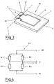
- FIG. 3 shows a further embodiment of the bending beam sensor 10 shown. And here is the additional tongue body 9 through two opposite cut-outs 12 cut free. The additional tongue body now exposed 9 is the one cut into the ceramic plate body 4 Main tongue body 7 opposite.
- bending line III are in the compression zone 1 and in the stretching zone 2 the resistors R1 and R2, R3 and R4 applied.
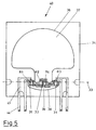
- Fig. 5 shows a bending beam sensor 40.
- a bending beam sensor 40 is in a substantially square ceramic plate body 34 along a main tongue section line 36 a main tongue body 37 and the opposite along an additional tongue cut line 38 cut out an additional tongue body 39.
- Both tongue bodies 37, 39 have a tongue-like configuration on.
- a bending line designated 33 are in the in the Resistance R2 and R4 and in the two outer compression zones 31, the resistance R1 and R3 applied.
- the resistors R1, R2, R3, R4 are connected by conductor tracks 43, of which connecting lines 44 lead to the outside.
- the resistors R1, R2 and R3 as well as the conductor tracks 43 are on the ceramic plate body 4, 34 in thick-film technology applied.
- the interconnected resistors R1, R2, R3, R4 result the Wheatstone bridge 46 shown in FIG. 4.
- a voltage wave UB with respect to ground M In a diagonal branch there is a voltage wave UB with respect to ground M.
- a sensor signal S is tapped in the other bridge branch.
- Ceramic plate body 4 instead of a ceramic plate body 4, 34, others can also be used Carrier materials in combination with suitable resistance materials Find use, e.g. B. metal plates with applied Thick film and thin film resistors or Glass, ceramics and with low accuracy requirements too Plastic plates with applied strain gauges.
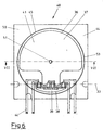
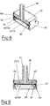
- 6 to 9 are structures of a pressure sensor with a Bending beam sensor shown in particular in FIG. 5.
- the bending beam sensor 40 is like the bending beam sensor 2, compared to the bending beam sensors 10 1 and 3, by an edge of the support element 4, 34th added that the main tongue element 7, 37 and the additional tongue element 9, 39 with the resistors R1, ... in the form that the resistors R1, R2, R3, R4 largely mechanically decoupled from the carrier element are so that this annular edge surface element 11 completely is used as a support and sealing surface 45.
- FIG. 6 and 7 show, along the support and Sealing surface 45 of the bending beam sensor 40 between two elastic Sealing elements 53, 54 clamped. With the elastic Sealing elements are each ring sealing elements.
- a housing body 50 which is in a connection hollow body 51 passes.
- a base body member 55 pressed into a base recess 56 for pressure compensation is introduced.
- the base body element 55 is a circuit board element educated.
- the bending beam sensor 40 is in the area of the ring sealing element 53 a gel layer body 52 for sealing the Cutting lines 36 and 38 applied.
- the bending beam sensor 40 is placed with its support surface on a washer element 64.
- the washer element can advantageously be made of metal because of the simple, precise manufacture and the high rigidity.
- the washer element and the bending beam sensor 40 are located in a housing made of plastic, which consists of a cover body element 60, to which a connecting hollow body element 61 connects.
- a gel layer body 62 is placed on the bending beam sensor 40 applied, which is surrounded by the sealing ring member 63 and seals the cut lines 36 and 38.
- the gel layer body 62 is made just like the gel layer body 52 made of a dielectric silicone gel, e.g. B. the brand Sylgard 527 A & B. This is a liquid Two-component silicone investment material of low viscosity, the is specifically designed to protect the electrical Properties of electronic circuits. essential to the invention is that the silicone gel as a membrane into a perfect new application context is brought.
- a dielectric silicone gel e.g. B. the brand Sylgard 527 A & B.
- This is a liquid Two-component silicone investment material of low viscosity, the is specifically designed to protect the electrical Properties of electronic circuits. essential to the invention is that the silicone gel as a membrane into a perfect new application context is brought.
- the transparent product is networked into a cushioning one at the place of use and self-healing as well as compliant gel-like Mass if the two components in a 1: 1 ratio - after Weight or volume - be mixed thoroughly.
- the cross-linked gel retains the stress relieving and self-healing properties of a liquid, loses the Flowability and thereby develops dimensional stability a solid elastomer.
- the unique properties remain at extremely high and low temperatures and are not lost even if the material continues is used at rest temperature.
- the gel layer body 52, 62 With the gel layer body 52, 62 one obtains, in connection with the tongue elements 37, 39, a closed surface, which as Pressure membrane acts. The result is a pressure measuring sensor, which the bending beam sensor and the pressure membrane to one component united.
- the main tongue and additional tongue cutting lines can be used to optimize the signal yield Adaptation to existing installation conditions and to avoid them can be varied by voltage peaks.
- the base body element is a printed circuit board with appropriate electronics and the necessary contact elements arranged on the housing.
- the advantageously thin main and additional tongue cut lines can with appropriate mechanical dimensioning in Connection with correspondingly mechanically stronger casting compounds be replaced by wider slots.
- the U- and ring-shaped carrier elements 4, 34 can in principle be interrupted at one or more points.
- the washer element 64 can, appropriate dimensioning provided to be part of the housing.
- the overload protection can also be part of the housing and need not must be integrated into the pane.
- Overload protection can also be created in the cover body element under negative pressure 60 are located.
- the overload protection can be adjustable, e.g. B. in Shape of an adjusting screw.
- housing body and cover can be used by all usual Connection methods such as screwing, flanging, welding, Gluing and the like are done.
- the base body member 55 becomes like the housing body 50 designed pressure-tight and also with a connecting hollow body element Mistake.
Landscapes
- Physics & Mathematics (AREA)
- General Physics & Mathematics (AREA)
- Measuring Fluid Pressure (AREA)
- Measurement Of Force In General (AREA)
- Force Measurement Appropriate To Specific Purposes (AREA)
- Pressure Sensors (AREA)
Applications Claiming Priority (2)
| Application Number | Priority Date | Filing Date | Title |
|---|---|---|---|
| DE10036495 | 2000-07-25 | ||
| DE2000136495 DE10036495C2 (de) | 2000-07-25 | 2000-07-25 | Kraftmessvorrichtung in Form eines Biegebalkensensors |
Publications (2)
| Publication Number | Publication Date |
|---|---|
| EP1176408A2 true EP1176408A2 (fr) | 2002-01-30 |
| EP1176408A3 EP1176408A3 (fr) | 2004-09-29 |
Family
ID=7650336
Family Applications (1)
| Application Number | Title | Priority Date | Filing Date |
|---|---|---|---|
| EP01117246A Withdrawn EP1176408A3 (fr) | 2000-07-25 | 2001-07-17 | Capteur à poutre de flexion avec éléments résistifs |
Country Status (2)
| Country | Link |
|---|---|
| EP (1) | EP1176408A3 (fr) |
| DE (1) | DE10036495C2 (fr) |
Cited By (4)
| Publication number | Priority date | Publication date | Assignee | Title |
|---|---|---|---|---|
| WO2006048278A1 (fr) * | 2004-11-03 | 2006-05-11 | Basell Polyolefine Gmbh | Transducteur de pression |
| JP2016125980A (ja) * | 2015-01-08 | 2016-07-11 | 国立大学法人 東京大学 | 圧力センサ |
| WO2021116276A1 (fr) | 2019-12-13 | 2021-06-17 | Innovationlab Gmbh | Capteur |
| LU102398B1 (en) | 2021-01-11 | 2022-07-11 | Innovationlab Gmbh | Sensor device |
Families Citing this family (1)
| Publication number | Priority date | Publication date | Assignee | Title |
|---|---|---|---|---|
| DE102012206655B4 (de) | 2012-04-23 | 2018-09-06 | Aktiebolaget Skf | Verfahren zur Ermittlung der radialen Vorspannkraft zwischen einem Dichtungselement und einem abzudichtenden Bauteil und Messelement hierfür |
Family Cites Families (7)
| Publication number | Priority date | Publication date | Assignee | Title |
|---|---|---|---|---|
| CH631013A5 (de) * | 1978-09-20 | 1982-07-15 | Schmid Roost J Sro Kugellagerw | Messvorrichtung. |
| DE3004031C2 (de) * | 1980-02-05 | 1990-03-29 | Philips Patentverwaltung Gmbh, 2000 Hamburg | Druckaufnehmer |
| DE3423696A1 (de) * | 1984-06-27 | 1986-01-09 | VEGA Grieshaber GmbH & Co, 7620 Wolfach | Druckmessaufnehmer |
| US4658651A (en) * | 1985-05-13 | 1987-04-21 | Transamerica Delaval Inc. | Wheatstone bridge-type transducers with reduced thermal shift |
| DE3814949C1 (fr) * | 1988-05-03 | 1989-08-03 | Robert Bosch Gmbh, 7000 Stuttgart, De | |
| DE4106288C2 (de) * | 1991-02-28 | 2001-05-31 | Bosch Gmbh Robert | Sensor zur Messung von Drücken oder Beschleunigungen |
| US5633552A (en) * | 1993-06-04 | 1997-05-27 | The Regents Of The University Of California | Cantilever pressure transducer |
-
2000
- 2000-07-25 DE DE2000136495 patent/DE10036495C2/de not_active Expired - Fee Related
-
2001
- 2001-07-17 EP EP01117246A patent/EP1176408A3/fr not_active Withdrawn
Cited By (5)
| Publication number | Priority date | Publication date | Assignee | Title |
|---|---|---|---|---|
| WO2006048278A1 (fr) * | 2004-11-03 | 2006-05-11 | Basell Polyolefine Gmbh | Transducteur de pression |
| JP2016125980A (ja) * | 2015-01-08 | 2016-07-11 | 国立大学法人 東京大学 | 圧力センサ |
| WO2021116276A1 (fr) | 2019-12-13 | 2021-06-17 | Innovationlab Gmbh | Capteur |
| LU102398B1 (en) | 2021-01-11 | 2022-07-11 | Innovationlab Gmbh | Sensor device |
| WO2022148881A1 (fr) | 2021-01-11 | 2022-07-14 | Innovationlab Gmbh | Dispositif capteur |
Also Published As
| Publication number | Publication date |
|---|---|
| DE10036495A1 (de) | 2002-02-14 |
| EP1176408A3 (fr) | 2004-09-29 |
| DE10036495C2 (de) | 2003-07-03 |
Similar Documents
| Publication | Publication Date | Title |
|---|---|---|
| DE69021325T2 (de) | Halbleiter-Druck-Messfühler verbunden mit einem Trägerelement. | |
| EP1550349B1 (fr) | Membrane et procede de realisation associe | |
| DE69707386T2 (de) | Druckwandler | |
| DE69715928T2 (de) | Fehlerkompensierter druckwandler | |
| DE69521890T2 (de) | Stabilisierter drucksensor | |
| DE3232817C1 (de) | Biegefeder | |
| DE102004006201B4 (de) | Drucksensor mit Siliziumchip auf einer Stahlmembran | |
| EP0087419B1 (fr) | Jauge de contrainte a couche mince et procede pour sa fabrication | |
| DE2709945A1 (de) | Kapazitiver druckwandler und verfahren zu dessen herstellung | |
| DE2906407C2 (de) | Piezoelektrisches Wandlerelement zum Einbau in Druck-, Kraft- oder Beschleunigungsaufnehmer | |
| CH698851B1 (de) | Piezoelektrischer Sensor. | |
| DE8407322U1 (de) | Piezoresestive druckmesszelle | |
| DE3928542A1 (de) | Halbleiter-druckwandler | |
| WO1998031998A1 (fr) | Capteur de pression de semi-conducteur | |
| DE4011734A1 (de) | Kapazitiver differenzdruckdetektor | |
| DE3702412C2 (fr) | ||
| EP0373536B1 (fr) | Capteur de pression capacitif résistant aux surcharges | |
| DE3404262A1 (de) | Kapazitiver messfuehler | |
| DE3026785A1 (de) | Druckwandler und verfahren zu seiner herstellung | |
| EP1176408A2 (fr) | Capteur à poutre de flexion avec éléments résistifs | |
| DE102016209241B4 (de) | Mikromechanisches Bauteil für eine Drucksensorvorrichtung | |
| EP0419611B1 (fr) | Procede pour la fabrication de capteurs de mesure d'efforts de compression | |
| DE102018106518A1 (de) | Sensorelement zur Druck- und Temperaturmessung | |
| EP3063518B1 (fr) | Élément détecteur capacitif à capacités de mesure et de référence intégrées | |
| EP0992778A2 (fr) | Capteur et son procédé de fabricage |
Legal Events
| Date | Code | Title | Description |
|---|---|---|---|
| PUAI | Public reference made under article 153(3) epc to a published international application that has entered the european phase |
Free format text: ORIGINAL CODE: 0009012 |
|
| AK | Designated contracting states |
Kind code of ref document: A2 Designated state(s): AT BE CH CY DE DK ES FI FR GB GR IE IT LI LU MC NL PT SE TR |
|
| AX | Request for extension of the european patent |
Free format text: AL;LT;LV;MK;RO;SI |
|
| RAP1 | Party data changed (applicant data changed or rights of an application transferred) |
Owner name: AB ELEKTRONIK SACHSEN GMBH |
|
| PUAL | Search report despatched |
Free format text: ORIGINAL CODE: 0009013 |
|
| AK | Designated contracting states |
Kind code of ref document: A3 Designated state(s): AT BE CH CY DE DK ES FI FR GB GR IE IT LI LU MC NL PT SE TR |
|
| AX | Request for extension of the european patent |
Extension state: AL LT LV MK RO SI |
|
| 17P | Request for examination filed |
Effective date: 20041025 |
|
| 17Q | First examination report despatched |
Effective date: 20050414 |
|
| AKX | Designation fees paid |
Designated state(s): AT BE CH CY DE DK ES FI FR GB GR IE IT LI LU MC NL PT SE TR |
|
| GRAP | Despatch of communication of intention to grant a patent |
Free format text: ORIGINAL CODE: EPIDOSNIGR1 |
|
| STAA | Information on the status of an ep patent application or granted ep patent |
Free format text: STATUS: THE APPLICATION IS DEEMED TO BE WITHDRAWN |
|
| 18D | Application deemed to be withdrawn |
Effective date: 20060927 |