EP1176545A2 - Former des images par laser avec point de dimension variable - Google Patents
Former des images par laser avec point de dimension variable Download PDFInfo
- Publication number
- EP1176545A2 EP1176545A2 EP01114875A EP01114875A EP1176545A2 EP 1176545 A2 EP1176545 A2 EP 1176545A2 EP 01114875 A EP01114875 A EP 01114875A EP 01114875 A EP01114875 A EP 01114875A EP 1176545 A2 EP1176545 A2 EP 1176545A2
- Authority
- EP
- European Patent Office
- Prior art keywords
- laser
- printing
- light source
- point
- imaging
- Prior art date
- Legal status (The legal status is an assumption and is not a legal conclusion. Google has not performed a legal analysis and makes no representation as to the accuracy of the status listed.)
- Granted
Links
- 238000003384 imaging method Methods 0.000 title claims description 55
- 238000000034 method Methods 0.000 claims description 6
- 230000001419 dependent effect Effects 0.000 claims 2
- 238000005286 illumination Methods 0.000 abstract 1
- 230000003287 optical effect Effects 0.000 description 3
- 230000007423 decrease Effects 0.000 description 2
- 238000011161 development Methods 0.000 description 2
- 238000005259 measurement Methods 0.000 description 2
- 241001295925 Gegenes Species 0.000 description 1
- 238000003491 array Methods 0.000 description 1
- 238000010276 construction Methods 0.000 description 1
- 239000000428 dust Substances 0.000 description 1
- 238000011065 in-situ storage Methods 0.000 description 1
- 239000002245 particle Substances 0.000 description 1
- 230000002123 temporal effect Effects 0.000 description 1
- 238000012546 transfer Methods 0.000 description 1
- 238000013519 translation Methods 0.000 description 1
Images



Classifications
-
- B—PERFORMING OPERATIONS; TRANSPORTING
- B41—PRINTING; LINING MACHINES; TYPEWRITERS; STAMPS
- B41J—TYPEWRITERS; SELECTIVE PRINTING MECHANISMS, i.e. MECHANISMS PRINTING OTHERWISE THAN FROM A FORME; CORRECTION OF TYPOGRAPHICAL ERRORS
- B41J2/00—Typewriters or selective printing mechanisms characterised by the printing or marking process for which they are designed
- B41J2/435—Typewriters or selective printing mechanisms characterised by the printing or marking process for which they are designed characterised by selective application of radiation to a printing material or impression-transfer material
- B41J2/447—Typewriters or selective printing mechanisms characterised by the printing or marking process for which they are designed characterised by selective application of radiation to a printing material or impression-transfer material using arrays of radiation sources
- B41J2/45—Typewriters or selective printing mechanisms characterised by the printing or marking process for which they are designed characterised by selective application of radiation to a printing material or impression-transfer material using arrays of radiation sources using light-emitting diode [LED] or laser arrays
- B41J2/451—Special optical means therefor, e.g. lenses, mirrors, focusing means
-
- B—PERFORMING OPERATIONS; TRANSPORTING
- B41—PRINTING; LINING MACHINES; TYPEWRITERS; STAMPS
- B41C—PROCESSES FOR THE MANUFACTURE OR REPRODUCTION OF PRINTING SURFACES
- B41C1/00—Forme preparation
- B41C1/10—Forme preparation for lithographic printing; Master sheets for transferring a lithographic image to the forme
- B41C1/1075—Mechanical aspects of on-press plate preparation
-
- B—PERFORMING OPERATIONS; TRANSPORTING
- B41—PRINTING; LINING MACHINES; TYPEWRITERS; STAMPS
- B41J—TYPEWRITERS; SELECTIVE PRINTING MECHANISMS, i.e. MECHANISMS PRINTING OTHERWISE THAN FROM A FORME; CORRECTION OF TYPOGRAPHICAL ERRORS
- B41J2/00—Typewriters or selective printing mechanisms characterised by the printing or marking process for which they are designed
- B41J2/435—Typewriters or selective printing mechanisms characterised by the printing or marking process for which they are designed characterised by selective application of radiation to a printing material or impression-transfer material
- B41J2/44—Typewriters or selective printing mechanisms characterised by the printing or marking process for which they are designed characterised by selective application of radiation to a printing material or impression-transfer material using single radiation source per colour, e.g. lighting beams or shutter arrangements
- B41J2/442—Typewriters or selective printing mechanisms characterised by the printing or marking process for which they are designed characterised by selective application of radiation to a printing material or impression-transfer material using single radiation source per colour, e.g. lighting beams or shutter arrangements using lasers
-
- B—PERFORMING OPERATIONS; TRANSPORTING
- B41—PRINTING; LINING MACHINES; TYPEWRITERS; STAMPS
- B41J—TYPEWRITERS; SELECTIVE PRINTING MECHANISMS, i.e. MECHANISMS PRINTING OTHERWISE THAN FROM A FORME; CORRECTION OF TYPOGRAPHICAL ERRORS
- B41J2/00—Typewriters or selective printing mechanisms characterised by the printing or marking process for which they are designed
- B41J2/435—Typewriters or selective printing mechanisms characterised by the printing or marking process for which they are designed characterised by selective application of radiation to a printing material or impression-transfer material
- B41J2/47—Typewriters or selective printing mechanisms characterised by the printing or marking process for which they are designed characterised by selective application of radiation to a printing material or impression-transfer material using the combination of scanning and modulation of light
Definitions
- the invention relates to a device for point-by-point imaging of printing areas with the help of at least one laser beam which is moved relative to the printing surface.
- Imaging printing plates in CtP computer-to-plate
- direct imaging Printing presses must be the distance between the printing surface and the optical system the imaging device are followed very precisely in order to achieve an optimal result receive.
- Deviations from the target distance between the printing surface and the imaging laser How strong the quality of the imaging result depends on the deviation from the target distance among other things by the beam quality of the laser and the selected beam parameters founded.
- Such autofocus systems can only work quickly to a limited extent. For example, if Laser optics process must accelerate a non-negligible mass quickly, exactly positioned and braked quickly. For high-frequency interference like her for example due to dirt under the printing surface, dust particles or through Kinks occur in the printing area are the standard times that such a system requires too long. Imaging errors therefore often occur.
- a multi-channel system i.e. H., an imaging device with multiple parallel laser beams, can typically not every single beam can be focused because the entire imaging optics is moved. In other words a compromise has to be found so that the deviation from the target distance of all simultaneous beams is minimal overall. in the general is the construction of a mechanical, by moving the Imaging optics acting autofocus system technically complex, needed appropriate space and causes relatively high costs.
- the object of the present invention is therefore to provide a device for point by point Imaging of printing areas with the help of at least one laser beam, which is relative to the Printing area is moved to provide with which a variable Imaging can be done without parts of the device, such as for example the imaging optics, must be moved mechanically in order to Compensate for fluctuations in the distance between the imaging optics and the printing surface.
- the imaging optics of an imaging device are typically set such that that at the target distance the focus, d. H. the plane in which the laser beam is has the smallest diameter, comes to lie exactly on the surface of the printing surface.
- a deviation from the target distance between the laser and the printing surface results in one Enlargement of the jet diameter on the printing surface and thus depending on how Laser parameters of power and focus diameter are set in one Enlargement or reduction of the pressure point.
- a detector Actual distance between the printing surface and the laser is detected, so that it has a setpoint can be compared. Depending on the deviation from the setpoint, the Light output with which imaging is carried out increases or decreases.
- Another way to vary the size of the pressure point is to use the Extend or shorten exposure time selectively. A combination of the Changes in performance and exposure time are also possible.
- the enlargement or reduction of the Pressure point due to a distance deviation: by the provided changeable laser power can be an adjustment of the pressure point size done so that an acceptable imaging result is achieved.
- the pressure point size is variable.
- the value of the required light output or Exposure time can be calculated from the measured distance.
- This function can z. B. in the raster generator, the pattern of dots to be imaged in a temporal Sequence of impulses for laser imaging are implemented. advantageously, a table, a so-called Lookup table, created and saved so that the required value is immediately available in situ Available.
- the device has point by point Imaging of printing surfaces on several laser beams, with which exposure is carried out simultaneously becomes.
- individually controllable diode laser arrays are preferred.
- the power or imaging time can vary for each individual laser in the array so that it is possible to achieve an acceptable imaging result because the The size of each pressure point written by a laser is variable and the size of the other pressure points is independent.
- the present invention requires far fewer moving parts than the known ones Autofocus systems and can therefore react to faults much more quickly. she also achieves a significantly better imaging result than a facility without Autofocus.
- the implementation of compact imaging equipment in an integrated form is much easier. It is associated with lower costs.
- Such a device can be inside or outside a printing unit or a Printing machine can be used for point-by-point imaging.
- FIG. 1 shows the variation of the spot size of a laser for point-by-point imaging shown by printing areas.
- the laser beam propagates along the optical axis 10, on which his intensity maximum is also located.
- focus 12 the Laser beam at its lowest waist.
- the focus 12 defines the target distance of the laser to the printing surface.
- Lines 18 indicate the variation in Limitation of the light spot as a function of the position along the direction of propagation. A greater intensity than the threshold intensity is in focus 12 in an area 110 reached for illustration.
- the area in which the intensity lies above the threshold intensity becomes smaller, because the transported energy flows through a larger cross-sectional area.
- arrested Laser intensity thus results in the area 112 in which the imaging threshold is exceeded.
- the Area 116 to be imaged is larger than the area reached with the recorded intensity 112. Consequently, according to the invention, the intensity of the laser is increased so that the area in which the threshold intensity for imaging is exceeded.
- the Threshold intensity is then exceeded in the entire area 118. At [bar booth 114 the threshold intensity is then reached in the entire region 116.
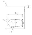
- FIG. 2 shows the generation of a printing point by relative movement of a laser beam against a printing surface.
- a laser beam with a spot 22 falls on a printing surface 20.
- the laser is scanned over the printing surface 20 in such a way that the threshold intensity for imaging is exceeded in the entire region 24.
- it is an elliptical Gaussian laser beam which has two different semiaxes.
- the longer spot diameter w x 26 is typically perpendicular to the direction of movement.
- the shorter spot diameter w y 28 lies in the direction of movement.
- 3a, 3b and 3c show examples of boundary lines of written pressure points of different laser parameters.
- the surface is shown on which the threshold intensity for imaging is exceeded.
- 3a shows the boundary line f of a pressure point with widths d x 9.3 micrometers and d y 10.6 micrometers.
- the boundary line u of a pressure point can also be seen, as it arises when deflected by 100 micrometers from the target distance with the laser power kept the same.
- Its width d x is 8.5 micrometers and its height d y is 9.8 micrometers.
- the laser wavelength is 830 nanometers and the diffraction index M 2 is 1.1. At this distance from the focus, the spots w x and w y are 8.8 micrometers and 7.7 micrometers, respectively.
- 3 a shows the boundary line a of a pressure point as can be achieved with the aid of the device according to the invention.
- the power of the laser is increased by 10%.
- the pressure point size can be made variable.
- 3 b shows an example of how a power adjustment can lead to a reduced pressure point.
- reduced performance which is optimized for writing a line
- the boundary line 1 of a pressure point of the width d x of 8.1 micrometers and the height d y of 9.5 micrometers is generated.
- the actual distance in turn deviates by 100 micrometers from the target distance in the focus of the laser.
- the spot diameters are w x 8.8 microns and w y 7.7 microns.
- FIG. 3 c shows an example of how an extension of the exposure time, in other words the duration of the laser beam, leads to an increase in the pressure point both in the x direction and in the y direction.
- a boundary line v of a pressure point can be seen, which is produced when the exposure is extended from 10 microseconds to 11 microseconds.
- the point created in this way has the widths d x 9.5 micrometers and d y 10.8 micrometers.
- the parameters of the generating beam are the same as for the beam which creates a pressure point with the boundary line u, as is also shown in Fig. 3a.
- the series of images shown in Fig. 3 a, 3 b and 3c exemplifies how one point-by-point imaging of printing areas using at least one laser beam variable pressure point size achieved by changeable laser power or exposure time becomes. Changes in distance between the printing surface and the laser focus are instead of with a Movement of the imaging optics, the laser itself or the printing surface, as in Auto focus systems is common, balanced by adjusting the laser power.
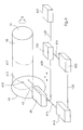
- the laser light source 40 generates a laser beam 42 which mediates an imaging optics 44 on the printing surface 48 located on a cylinder 46 in the Point 410 is mapped.
- the cylinder 46 is rotatable about its axis of symmetry. This Rotation is indicated by the double arrow B.
- the laser light source 40 can be parallel to Axis of symmetry of the cylinder 46 can be moved in a linear manner, which by the Double arrow A is marked.
- the cylinder 46 rotates with the Printing surface 48 according to the rotational movement B, and the laser light source 40 moves along the cylinder according to the translation direction A.
- the path of the pixel 410 is indicated by the line 412.
- the rangefinder 414 emits a light beam 416, which reaches the printing surface 48 in the pixel 418.
- the necessary information about the distance between the laser light source 40 and the pixel 410, which is used for imaging can be obtained for the printing surface 48.
- Via a connection for exchanging data and / or control signals 420 the rangefinder 414 with a device for calculating the necessary Laser power 422 linked.
- the connection for calculation is via connection 424 the necessary laser power or exposure time 422 with the laser control 426 linked, which in particular can determine the laser power.
- Data and / or Control signals between laser control 426 and laser light source 40 are via the Transfer connection 428.
- the laser controller 426 can do so can also be linked to the machine control 432 via a connection 430.
- the laser light source 40 consists of a laser diode array, the individual lasers of which can be controlled separately. It a simultaneous imaging of several pressure points can then take place, the Size is variable. The deviation of the actual position from the target position of the printing surface to the laser focus through the changeable laser power or Exposure time can be compensated.
Landscapes
- Physics & Mathematics (AREA)
- Optics & Photonics (AREA)
- Engineering & Computer Science (AREA)
- Mechanical Engineering (AREA)
- Manufacturing & Machinery (AREA)
- Health & Medical Sciences (AREA)
- General Health & Medical Sciences (AREA)
- Toxicology (AREA)
- Manufacture Or Reproduction Of Printing Formes (AREA)
- Laser Beam Printer (AREA)
- Exposure And Positioning Against Photoresist Photosensitive Materials (AREA)
- Printers Or Recording Devices Using Electromagnetic And Radiation Means (AREA)
- Dot-Matrix Printers And Others (AREA)
- Facsimile Heads (AREA)
- Electronic Switches (AREA)
- Laser Surgery Devices (AREA)
Applications Claiming Priority (2)
| Application Number | Priority Date | Filing Date | Title |
|---|---|---|---|
| DE10035848A DE10035848A1 (de) | 2000-07-24 | 2000-07-24 | Laserbebilderung mit variabler Druckpuktgröße |
| DE10035848 | 2000-07-24 |
Publications (3)
| Publication Number | Publication Date |
|---|---|
| EP1176545A2 true EP1176545A2 (fr) | 2002-01-30 |
| EP1176545A3 EP1176545A3 (fr) | 2003-08-06 |
| EP1176545B1 EP1176545B1 (fr) | 2005-12-28 |
Family
ID=7649933
Family Applications (1)
| Application Number | Title | Priority Date | Filing Date |
|---|---|---|---|
| EP01114875A Expired - Lifetime EP1176545B1 (fr) | 2000-07-24 | 2001-06-29 | Former des images par laser avec point de dimension variable |
Country Status (10)
| Country | Link |
|---|---|
| US (1) | US6836282B2 (fr) |
| EP (1) | EP1176545B1 (fr) |
| JP (1) | JP4933001B2 (fr) |
| CN (1) | CN1199802C (fr) |
| AT (1) | ATE314697T1 (fr) |
| CA (1) | CA2350448C (fr) |
| CZ (1) | CZ297292B6 (fr) |
| DE (2) | DE10035848A1 (fr) |
| HK (1) | HK1043090B (fr) |
| IL (1) | IL144484A0 (fr) |
Cited By (2)
| Publication number | Priority date | Publication date | Assignee | Title |
|---|---|---|---|---|
| US7280132B2 (en) | 2002-12-09 | 2007-10-09 | Heidelberger Druckmaschinen Ag | Method and device for imaging a printing form |
| EP2492103A1 (fr) * | 2011-02-28 | 2012-08-29 | Ricoh Company, Ltd. | Procédé et appareil de traitement d'images |
Families Citing this family (8)
| Publication number | Priority date | Publication date | Assignee | Title |
|---|---|---|---|---|
| DE10212937B4 (de) | 2002-03-22 | 2009-12-17 | Heidelberger Druckmaschinen Ag | Verfahren zur Einstellung der Bildlinienbreite in einem Belichter |
| US7219453B2 (en) * | 2003-01-24 | 2007-05-22 | Baker Robert E | Floatdown implement for small vehicles |
| CN1824499A (zh) * | 2005-02-24 | 2006-08-30 | 海德堡印刷机械股份公司 | 用于制造印版的方法 |
| CN103331988B (zh) * | 2013-06-19 | 2015-02-18 | 汪海洋 | 一种柔性印刷版的制版方法和主曝光设备 |
| DE102016208479A1 (de) * | 2016-05-18 | 2017-11-23 | Roth + Weber Gmbh | Elektrofotografischer Großformat-Farbdrucker |
| CN114734636B (zh) * | 2022-04-20 | 2023-12-19 | 浙江正向增材制造有限公司 | 光固化打印装置及打印方法 |
| CN114710628B (zh) * | 2022-04-21 | 2023-12-05 | 深圳市先地图像科技有限公司 | 一种图像曝光方法、计算机设备及存储介质 |
| CN115384060B (zh) * | 2022-09-16 | 2025-08-29 | 杭州爱新凯科技有限公司 | 基于光斑质量检测仪的3d打印装置及光斑质量检测方法 |
Citations (1)
| Publication number | Priority date | Publication date | Assignee | Title |
|---|---|---|---|---|
| US5764272A (en) | 1995-09-12 | 1998-06-09 | Eastman Kodak Company | Autofocus mechanism for laser imager |
Family Cites Families (14)
| Publication number | Priority date | Publication date | Assignee | Title |
|---|---|---|---|---|
| JPS59146068A (ja) * | 1983-02-08 | 1984-08-21 | Nippon Telegr & Teleph Corp <Ntt> | 記録方法 |
| JPS6016058A (ja) * | 1983-07-08 | 1985-01-26 | Hitachi Ltd | 光ビ−ム走査装置 |
| JP3181050B2 (ja) * | 1990-04-20 | 2001-07-03 | 株式会社日立製作所 | 投影露光方法およびその装置 |
| US5278581A (en) * | 1990-09-17 | 1994-01-11 | Kabushiki Kaisha Toshiba | Printer for printing and image formed of 2-dimensionally arranged pixels, and method of printing the same |
| DK69492D0 (da) * | 1992-05-26 | 1992-05-26 | Purup Prepress As | Apparat til exponering af et medie, apparat til punktexponering af et medie, samt en indretning til fastholdelse af et medie |
| ES2102094T3 (es) * | 1994-04-26 | 1997-07-16 | Schablonentechnik Kufstein Ag | Procedimiento y dispositivo para la fabricacion de una plantilla de serigrafia. |
| US5819661A (en) * | 1995-01-23 | 1998-10-13 | Presstek, Inc. | Method and apparatus for laser imaging of lithographic printing members by thermal non-ablative transfer |
| US5666577A (en) * | 1995-08-31 | 1997-09-09 | Eastman Kodak Company | System for switching pointing indices in laser aimed cameras |
| IL116885A0 (en) * | 1996-01-24 | 1996-05-14 | Scitex Corp Ltd | An imaging apparatus for exposing a printing member |
| US5822345A (en) * | 1996-07-08 | 1998-10-13 | Presstek, Inc. | Diode-pumped laser system and method |
| JPH1024546A (ja) * | 1996-07-10 | 1998-01-27 | Sony Corp | レーザ製版装置及びレーザ製版方法 |
| JPH1034866A (ja) * | 1996-07-24 | 1998-02-10 | Sony Corp | オートフォーカス機能付きレーザ製版装置及びオートフォーカス検出用レーザの外乱を除去する方法 |
| US6072511A (en) * | 1997-12-12 | 2000-06-06 | Presstek, Inc. | Method and apparatus for diode-laser imaging with compensation for output variations |
| DE19848455A1 (de) * | 1998-10-21 | 2000-04-27 | Heidelberger Druckmasch Ag | Vorrichtung zur Einstellung der Position eines zylindrischen Bildträgers in Bezug auf einen Abtastkopf |
-
2000
- 2000-07-24 DE DE10035848A patent/DE10035848A1/de not_active Withdrawn
-
2001
- 2001-06-13 CA CA002350448A patent/CA2350448C/fr not_active Expired - Fee Related
- 2001-06-29 DE DE50108510T patent/DE50108510D1/de not_active Expired - Lifetime
- 2001-06-29 EP EP01114875A patent/EP1176545B1/fr not_active Expired - Lifetime
- 2001-06-29 CN CNB011199504A patent/CN1199802C/zh not_active Expired - Fee Related
- 2001-06-29 AT AT01114875T patent/ATE314697T1/de not_active IP Right Cessation
- 2001-07-18 CZ CZ20012612A patent/CZ297292B6/cs not_active IP Right Cessation
- 2001-07-22 IL IL14448401A patent/IL144484A0/xx not_active IP Right Cessation
- 2001-07-23 US US09/911,206 patent/US6836282B2/en not_active Expired - Fee Related
- 2001-07-24 JP JP2001223108A patent/JP4933001B2/ja not_active Expired - Fee Related
-
2002
- 2002-07-09 HK HK02105091.5A patent/HK1043090B/zh not_active IP Right Cessation
Patent Citations (1)
| Publication number | Priority date | Publication date | Assignee | Title |
|---|---|---|---|---|
| US5764272A (en) | 1995-09-12 | 1998-06-09 | Eastman Kodak Company | Autofocus mechanism for laser imager |
Cited By (3)
| Publication number | Priority date | Publication date | Assignee | Title |
|---|---|---|---|---|
| US7280132B2 (en) | 2002-12-09 | 2007-10-09 | Heidelberger Druckmaschinen Ag | Method and device for imaging a printing form |
| EP2492103A1 (fr) * | 2011-02-28 | 2012-08-29 | Ricoh Company, Ltd. | Procédé et appareil de traitement d'images |
| US8643689B2 (en) | 2011-02-28 | 2014-02-04 | Ricoh Company, Ltd. | Image processing method and image processing apparatus |
Also Published As
| Publication number | Publication date |
|---|---|
| CA2350448A1 (fr) | 2002-01-24 |
| US20020044196A1 (en) | 2002-04-18 |
| CZ297292B6 (cs) | 2006-10-11 |
| DE10035848A1 (de) | 2002-02-07 |
| HK1043090B (zh) | 2005-12-09 |
| ATE314697T1 (de) | 2006-01-15 |
| EP1176545B1 (fr) | 2005-12-28 |
| DE50108510D1 (de) | 2006-02-02 |
| CN1334199A (zh) | 2002-02-06 |
| CZ20012612A3 (cs) | 2002-03-13 |
| JP2002127355A (ja) | 2002-05-08 |
| CN1199802C (zh) | 2005-05-04 |
| US6836282B2 (en) | 2004-12-28 |
| CA2350448C (fr) | 2007-01-09 |
| IL144484A0 (en) | 2002-05-23 |
| EP1176545A3 (fr) | 2003-08-06 |
| HK1043090A1 (en) | 2002-09-06 |
| JP4933001B2 (ja) | 2012-05-16 |
Similar Documents
| Publication | Publication Date | Title |
|---|---|---|
| EP1168813B1 (fr) | Source laser d'illumination à plusieurs faisceaux et procédé d'entrelacement de lignes de balayage à trame pour l'exposition de plaques d'impression | |
| DE69809627T2 (de) | Strahlenabbildungssystem mit mehrfacher Lichtfleckgrösse und Verfahren | |
| DE69421957T2 (de) | Verfahren und Vorrichtung zum Ausgleich von Positionsoffsetfehlern von Druckkopfelementen beim elektronisch gesteuerten Rasterdruck | |
| DE602006000434T3 (de) | Druckplattenherstellungsgerät | |
| DE3314963C2 (fr) | ||
| EP1373981B1 (fr) | Dispositif de lithographie à lentille mobile pour la formation d'hologrammes numériques | |
| DE69327425T2 (de) | Drucktechniken mit mehreren Laserdioden | |
| WO2012130666A1 (fr) | Procédé de détermination de la position du point focal d'un faisceau laser dans le champ d'action ou l'espace de travail de ce dernier | |
| EP0173849A2 (fr) | Lithographie par rayon laser | |
| EP1176545B1 (fr) | Former des images par laser avec point de dimension variable | |
| EP1373983B1 (fr) | Lithographe pourvu d'un masque de declenchement, procede de production d'hologrammes numeriques dans un moyen memoire et microscope | |
| DE3889854T2 (de) | Abtaster für einen elektrophotografischen Laserdrucker mit vielfachem Abtastfleck. | |
| DE3935239A1 (de) | Abtastgeraet | |
| DE102021111949A1 (de) | Vorrichtung zur scannenden Messung des Abstands zu einem Objekt | |
| EP2110699A2 (fr) | Dispositif et procédé destinés à l'éclairage d'une scène d'objet | |
| EP1235102A2 (fr) | Procédé et appareil de balayage à faisceaux multiples pour ablation par laser lors de la fabrication de plaques flexographiques | |
| DE4127919C2 (de) | Lichtaufzeichnungsvorrichtung | |
| EP1211066B1 (fr) | Dispositif d'imagerie | |
| DE10251866A1 (de) | Lichttaster und Bilderzeugungsvorrichtung mit Selbigem | |
| DE10233491B4 (de) | Kompakte Einrichtung zur Bebilderung einer Druckform | |
| DE10353869A1 (de) | Verfahren und Einrichtung zur Bebilderung einer Druckform | |
| DE10124215A1 (de) | Bebilderungseinrichtung zur Erzeugung einer Anzahl von Bildpunkten in einer Projektionslinie | |
| WO2022043134A1 (fr) | Dispositif et procédé de génération d'images d'un réseau de sources de lumières | |
| WO2022074094A1 (fr) | Appareil et procédé pour générer une ligne laser définie sur un plan de travail | |
| DE102017210098B4 (de) | Scanvorrichtung mit einer Scankopfvorrichtung zum Reflektieren oder Transmittieren von Strahlen für einen Scanner sowie Verfahren zum Reflektieren oder Transmittieren von Strahlen für einen Scanner |
Legal Events
| Date | Code | Title | Description |
|---|---|---|---|
| PUAI | Public reference made under article 153(3) epc to a published international application that has entered the european phase |
Free format text: ORIGINAL CODE: 0009012 |
|
| AK | Designated contracting states |
Kind code of ref document: A2 Designated state(s): AT BE CH CY DE DK ES FI FR GB GR IE IT LI LU MC NL PT SE TR |
|
| AX | Request for extension of the european patent |
Free format text: AL;LT;LV;MK;RO;SI |
|
| PUAL | Search report despatched |
Free format text: ORIGINAL CODE: 0009013 |
|
| AK | Designated contracting states |
Designated state(s): AT BE CH CY DE DK ES FI FR GB GR IE IT LI LU MC NL PT SE TR |
|
| AX | Request for extension of the european patent |
Extension state: AL LT LV MK RO SI |
|
| RIC1 | Information provided on ipc code assigned before grant |
Ipc: 7B 41C 1/10 B Ipc: 7B 41J 2/455 B Ipc: 7H 04N 1/401 B Ipc: 7G 06K 15/12 A Ipc: 7B 41J 2/475 B Ipc: 7H 04N 1/40 B Ipc: 7G 02B 7/28 B |
|
| 17P | Request for examination filed |
Effective date: 20030627 |
|
| 17Q | First examination report despatched |
Effective date: 20040316 |
|
| AKX | Designation fees paid |
Designated state(s): AT BE CH CY DE DK ES FI FR GB GR IE IT LI LU MC NL PT SE TR |
|
| GRAP | Despatch of communication of intention to grant a patent |
Free format text: ORIGINAL CODE: EPIDOSNIGR1 |
|
| GRAS | Grant fee paid |
Free format text: ORIGINAL CODE: EPIDOSNIGR3 |
|
| GRAA | (expected) grant |
Free format text: ORIGINAL CODE: 0009210 |
|
| AK | Designated contracting states |
Kind code of ref document: B1 Designated state(s): AT BE CH CY DE DK ES FI FR GB GR IE IT LI LU MC NL PT SE TR |
|
| PG25 | Lapsed in a contracting state [announced via postgrant information from national office to epo] |
Ref country code: IT Free format text: LAPSE BECAUSE OF FAILURE TO SUBMIT A TRANSLATION OF THE DESCRIPTION OR TO PAY THE FEE WITHIN THE PRESCRIBED TIME-LIMIT;WARNING: LAPSES OF ITALIAN PATENTS WITH EFFECTIVE DATE BEFORE 2007 MAY HAVE OCCURRED AT ANY TIME BEFORE 2007. THE CORRECT EFFECTIVE DATE MAY BE DIFFERENT FROM THE ONE RECORDED. Effective date: 20051228 Ref country code: FI Free format text: LAPSE BECAUSE OF FAILURE TO SUBMIT A TRANSLATION OF THE DESCRIPTION OR TO PAY THE FEE WITHIN THE PRESCRIBED TIME-LIMIT Effective date: 20051228 Ref country code: IE Free format text: LAPSE BECAUSE OF FAILURE TO SUBMIT A TRANSLATION OF THE DESCRIPTION OR TO PAY THE FEE WITHIN THE PRESCRIBED TIME-LIMIT Effective date: 20051228 Ref country code: NL Free format text: LAPSE BECAUSE OF FAILURE TO SUBMIT A TRANSLATION OF THE DESCRIPTION OR TO PAY THE FEE WITHIN THE PRESCRIBED TIME-LIMIT Effective date: 20051228 |
|
| REG | Reference to a national code |
Ref country code: GB Ref legal event code: FG4D Free format text: NOT ENGLISH |
|
| REG | Reference to a national code |
Ref country code: CH Ref legal event code: EP |
|
| REG | Reference to a national code |
Ref country code: IE Ref legal event code: FG4D Free format text: LANGUAGE OF EP DOCUMENT: GERMAN |
|
| REF | Corresponds to: |
Ref document number: 50108510 Country of ref document: DE Date of ref document: 20060202 Kind code of ref document: P |
|
| PG25 | Lapsed in a contracting state [announced via postgrant information from national office to epo] |
Ref country code: SE Free format text: LAPSE BECAUSE OF FAILURE TO SUBMIT A TRANSLATION OF THE DESCRIPTION OR TO PAY THE FEE WITHIN THE PRESCRIBED TIME-LIMIT Effective date: 20060328 Ref country code: DK Free format text: LAPSE BECAUSE OF FAILURE TO SUBMIT A TRANSLATION OF THE DESCRIPTION OR TO PAY THE FEE WITHIN THE PRESCRIBED TIME-LIMIT Effective date: 20060328 Ref country code: GR Free format text: LAPSE BECAUSE OF FAILURE TO SUBMIT A TRANSLATION OF THE DESCRIPTION OR TO PAY THE FEE WITHIN THE PRESCRIBED TIME-LIMIT Effective date: 20060328 |
|
| PG25 | Lapsed in a contracting state [announced via postgrant information from national office to epo] |
Ref country code: ES Free format text: LAPSE BECAUSE OF FAILURE TO SUBMIT A TRANSLATION OF THE DESCRIPTION OR TO PAY THE FEE WITHIN THE PRESCRIBED TIME-LIMIT Effective date: 20060408 |
|
| GBT | Gb: translation of ep patent filed (gb section 77(6)(a)/1977) |
Effective date: 20060331 |
|
| PG25 | Lapsed in a contracting state [announced via postgrant information from national office to epo] |
Ref country code: PT Free format text: LAPSE BECAUSE OF FAILURE TO SUBMIT A TRANSLATION OF THE DESCRIPTION OR TO PAY THE FEE WITHIN THE PRESCRIBED TIME-LIMIT Effective date: 20060529 |
|
| NLV1 | Nl: lapsed or annulled due to failure to fulfill the requirements of art. 29p and 29m of the patents act | ||
| PG25 | Lapsed in a contracting state [announced via postgrant information from national office to epo] |
Ref country code: BE Free format text: LAPSE BECAUSE OF NON-PAYMENT OF DUE FEES Effective date: 20060630 Ref country code: MC Free format text: LAPSE BECAUSE OF NON-PAYMENT OF DUE FEES Effective date: 20060630 |
|
| REG | Reference to a national code |
Ref country code: IE Ref legal event code: FD4D |
|
| PLBE | No opposition filed within time limit |
Free format text: ORIGINAL CODE: 0009261 |
|
| STAA | Information on the status of an ep patent application or granted ep patent |
Free format text: STATUS: NO OPPOSITION FILED WITHIN TIME LIMIT |
|
| 26N | No opposition filed |
Effective date: 20060929 |
|
| EN | Fr: translation not filed | ||
| PG25 | Lapsed in a contracting state [announced via postgrant information from national office to epo] |
Ref country code: AT Free format text: LAPSE BECAUSE OF NON-PAYMENT OF DUE FEES Effective date: 20060629 |
|
| BERE | Be: lapsed |
Owner name: HEIDELBERGER DRUCKMASCHINEN A.G. Effective date: 20060630 |
|
| PG25 | Lapsed in a contracting state [announced via postgrant information from national office to epo] |
Ref country code: FR Free format text: LAPSE BECAUSE OF FAILURE TO SUBMIT A TRANSLATION OF THE DESCRIPTION OR TO PAY THE FEE WITHIN THE PRESCRIBED TIME-LIMIT Effective date: 20070216 |
|
| PG25 | Lapsed in a contracting state [announced via postgrant information from national office to epo] |
Ref country code: LU Free format text: LAPSE BECAUSE OF NON-PAYMENT OF DUE FEES Effective date: 20060629 Ref country code: TR Free format text: LAPSE BECAUSE OF FAILURE TO SUBMIT A TRANSLATION OF THE DESCRIPTION OR TO PAY THE FEE WITHIN THE PRESCRIBED TIME-LIMIT Effective date: 20051228 |
|
| PG25 | Lapsed in a contracting state [announced via postgrant information from national office to epo] |
Ref country code: FR Free format text: LAPSE BECAUSE OF FAILURE TO SUBMIT A TRANSLATION OF THE DESCRIPTION OR TO PAY THE FEE WITHIN THE PRESCRIBED TIME-LIMIT Effective date: 20051228 Ref country code: CY Free format text: LAPSE BECAUSE OF FAILURE TO SUBMIT A TRANSLATION OF THE DESCRIPTION OR TO PAY THE FEE WITHIN THE PRESCRIBED TIME-LIMIT Effective date: 20051228 |
|
| PGFP | Annual fee paid to national office [announced via postgrant information from national office to epo] |
Ref country code: DE Payment date: 20120630 Year of fee payment: 12 Ref country code: CH Payment date: 20120626 Year of fee payment: 12 |
|
| PGFP | Annual fee paid to national office [announced via postgrant information from national office to epo] |
Ref country code: GB Payment date: 20120626 Year of fee payment: 12 |
|
| REG | Reference to a national code |
Ref country code: CH Ref legal event code: PL |
|
| GBPC | Gb: european patent ceased through non-payment of renewal fee |
Effective date: 20130629 |
|
| REG | Reference to a national code |
Ref country code: DE Ref legal event code: R119 Ref document number: 50108510 Country of ref document: DE Effective date: 20140101 |
|
| PG25 | Lapsed in a contracting state [announced via postgrant information from national office to epo] |
Ref country code: CH Free format text: LAPSE BECAUSE OF NON-PAYMENT OF DUE FEES Effective date: 20130630 Ref country code: GB Free format text: LAPSE BECAUSE OF NON-PAYMENT OF DUE FEES Effective date: 20130629 Ref country code: LI Free format text: LAPSE BECAUSE OF NON-PAYMENT OF DUE FEES Effective date: 20130630 Ref country code: DE Free format text: LAPSE BECAUSE OF NON-PAYMENT OF DUE FEES Effective date: 20140101 |