EP1176567A2 - Dispositif de surveillance - Google Patents
Dispositif de surveillance Download PDFInfo
- Publication number
- EP1176567A2 EP1176567A2 EP01117913A EP01117913A EP1176567A2 EP 1176567 A2 EP1176567 A2 EP 1176567A2 EP 01117913 A EP01117913 A EP 01117913A EP 01117913 A EP01117913 A EP 01117913A EP 1176567 A2 EP1176567 A2 EP 1176567A2
- Authority
- EP
- European Patent Office
- Prior art keywords
- monitoring device
- receiver
- transmitter
- time
- transmitter signal
- Prior art date
- Legal status (The legal status is an assumption and is not a legal conclusion. Google has not performed a legal analysis and makes no representation as to the accuracy of the status listed.)
- Granted
Links
Images

Classifications
-
- G—PHYSICS
- G08—SIGNALLING
- G08B—SIGNALLING SYSTEMS, e.g. PERSONAL CALLING SYSTEMS; ORDER TELEGRAPHS; ALARM SYSTEMS
- G08B25/00—Alarm systems in which the location of the alarm condition is signalled to a central station, e.g. fire or police telegraphic systems
- G08B25/009—Signalling of the alarm condition to a substation whose identity is signalled to a central station, e.g. relaying alarm signals in order to extend communication range
-
- G—PHYSICS
- G08—SIGNALLING
- G08B—SIGNALLING SYSTEMS, e.g. PERSONAL CALLING SYSTEMS; ORDER TELEGRAPHS; ALARM SYSTEMS
- G08B25/00—Alarm systems in which the location of the alarm condition is signalled to a central station, e.g. fire or police telegraphic systems
- G08B25/008—Alarm setting and unsetting, i.e. arming or disarming of the security system
-
- G—PHYSICS
- G08—SIGNALLING
- G08B—SIGNALLING SYSTEMS, e.g. PERSONAL CALLING SYSTEMS; ORDER TELEGRAPHS; ALARM SYSTEMS
- G08B25/00—Alarm systems in which the location of the alarm condition is signalled to a central station, e.g. fire or police telegraphic systems
- G08B25/01—Alarm systems in which the location of the alarm condition is signalled to a central station, e.g. fire or police telegraphic systems characterised by the transmission medium
- G08B25/10—Alarm systems in which the location of the alarm condition is signalled to a central station, e.g. fire or police telegraphic systems characterised by the transmission medium using wireless transmission systems
-
- G—PHYSICS
- G08—SIGNALLING
- G08B—SIGNALLING SYSTEMS, e.g. PERSONAL CALLING SYSTEMS; ORDER TELEGRAPHS; ALARM SYSTEMS
- G08B25/00—Alarm systems in which the location of the alarm condition is signalled to a central station, e.g. fire or police telegraphic systems
- G08B25/007—Details of data content structure of message packets; data protocols
Definitions
- the invention relates to a monitoring device with battery operated Monitoring devices, each with an alarm device have, and in particular a monitoring device with several smoke detectors forming a radio network.
- a monitoring device is used to identify certain dangerous situations to recognize and report in different places. For example, smoke detectors or intrusion detectors are known which each capture a room or an area and alarm signals deliver if the event to be monitored in this area entry.
- the installation effort for monitoring devices to reduce battery-powered monitoring devices developed by the user without further wiring can be installed. Every monitoring device is provided with its own alarm device. In the event of a response for example, an acoustic alarm is generated.
- a acoustic signal generated by a monitoring device by people who are in other rooms is not perceived.
- the alarm device sounds a monitoring device installed in the basement, so it can be assumed that this alarm in a room that is on the first floor, is not heard.
- the invention has for its object a monitoring device to create with battery powered monitoring devices which enables a long service life of the battery, i.e. allows long battery replacement cycles.
- the transmitter and receiver each have high power consumption when activated.
- the transmitter only needs to be activated if the associated detector has detected an event to be reported. This means, that the transmitter is switched off or in a snooze function can be held.
- the recipient should actually be permanently activated to respond to a broadcast signal from another Monitoring device to be able to respond.
- the receiver only in time intervals for one activated for a short time. In the event of a monitoring device responding the transmitter sends for a period of time that is greater than a time interval for receiver activation, a Transmitter signal off. The receiver turns on at predetermined intervals turned on briefly to listen for transmitter signals available.
- the invention is based on the idea from that it is generally tolerable if at a network of monitoring devices between the triggering Alarm and the last triggered alarm a time delay lies if this time delay is a certain predetermined one Dimension does not exceed.
- the maximum possible time delay can, for example, in the case of a smoke alarm system about 50 seconds. With this compromise, extend the battery life to about 2 years.
- the monitoring device has monitoring devices who are completely self-sufficient and neither Network connection still need a transmission network. thats why installation is particularly easy.
- the monitoring devices just need to be set up and turned on.
- the monitoring device can be a fire alarm device, an access monitoring device or a motion detection device his.
- the transmitter in time intervals sends out a short transmitter signal and that the Receiver is reactivated for a follow-up time, if there is a transmitter signal during receiver activation is received, the follow-up time being greater than the time interval of the transmitter signals.
- the transmitter first creates the over the specified period of time Transmitter signal that from all monitoring devices to different Times is recognized. After the time period is over to protect the battery of the sending monitoring device Transmitter signal reduced to short signals. These each trigger the receivers of the other monitoring devices in the Way that the receivers remain permanently activated as long as the message status continues. This prevents the battery of the sending monitoring device by a permanent one Sending state is too stressed.
- transmitter signals digital telegrams which certain other Address monitoring devices. This way you can set which monitoring devices communicate with each other.
- the transmitter signal may be a Contains alarm information that indicates an alarm condition from the condition distinguishes in which only one test button is pressed has been. When a test button is pressed, the alarm can be given during the duration of the relatively long run-on time can be prevented.
- a monitoring device 10 which has no mains connection and an internal battery 11 is supplied.
- the battery 11 is contained in a detector 12, which is a smoke detector.
- a test button 13 On the smoke detector 12 is also provided a test button 13 which can be operated to the function of the monitoring device testing.
- a control unit 14 is connected, which with the detector performs bidirectional data traffic.
- the Detector 12 is provided with an acoustic alarm device 15.
- the control unit 14 also contains an input switch 16, on which a multi-digit code number can be entered, to determine the address of the relevant monitoring device 10.
- the control unit 14 stands with a transmitter S and a receiver E connected.
- the transmitter S is equipped with a transmission antenna 17 provided and the receiver E with a receiving antenna 18th
- FIG Several identical monitoring devices 10 are, for example, in FIG distributed over the different floors of a building. You can communicate with each other over the radio link.
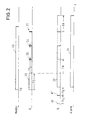
- the detector 12 When the detector 12 reports a dangerous situation, it generates a signal 20 according to FIG. 2, which begins at time t 0 and continues until the response state of the detector has ended.
- the transmitter S then sends a signal 22 as the transmitter signal 21, which begins at time t 0 and extends over a fixed period of time TS. This time span is 60 seconds here. Before the time t 0 the transmitter was switched off, ie in a slumber state.
- the activation line of a receiver E of another monitoring device is shown in the third line, which receives the signals of the first monitoring device.
- the receiver E of the "listening" monitoring device is activated for a short time.
- the signal for activating the receiver can be generated either by the control unit 14 or, in the case of the smoke detector, by the detector 12.
- the activation times are labeled AT.
- Time intervals TI E of the receiver activation extend between two activation times AT.
- a time interval TI E has a duration of 40 to 50 sec.
- the activation time AT has a duration of approximately 1 sec.
- an activation time AT certainly falls within the time period TS.
- the receiver E recognizes that the transmitter S is transmitting a transmitter signal 21.
- the receiver E is then activated, which is designated by 23 in FIG.
- the receiver remains activated as long as the transmitter signal 21 is received, and also for a follow-up time TN.
- the transmitter signal is interrupted for an interval TI S and then a short transmitter signal S is transmitted, which has a duration of 1 sec. Since each transmitter signal SS falls into the activation state of the receiver E, the lag time TN is retriggered for each transmitter signal S, so that the receiver E remains permanently switched on.
- the short transmitter signals SS are generated as long as the Message status 20 persists. On the last short transmitter signal SS the delay time TN then expires in the receiver and then the receiver E is stopped.
- the alarm state 24 is acoustic alarm device 15 belonging to the receiver E. shown.
- the alarm device is operated until the continuous reception state of the receiver E has ended.
- the transmitter signals 21 contain digital telegrams, which the Address of the sending and / or designated monitoring device specify. If the receiver of a monitoring device is switched on and the signal of another monitoring device receives, he compares the entered set Address with the received address and if both match, the alarm signal 24 is triggered. Data telegrams are also during the short transmitter signals SS transmitted and evaluated in the receiver E.
- test button 13 simulates a triggering of the Detector 12, however, is in the telegrams of signal 22 additional bit set, which indicates that it is a Test acts.
- the other monitoring devices report this test with an intermittent tone that differs from the normal Alarm tone differs.
- the delay time TN suppressed so that the acoustic alarm does not have the entire run-on time runs.
Landscapes
- Business, Economics & Management (AREA)
- Emergency Management (AREA)
- Physics & Mathematics (AREA)
- General Physics & Mathematics (AREA)
- Engineering & Computer Science (AREA)
- Computer Security & Cryptography (AREA)
- Computer Networks & Wireless Communication (AREA)
- Alarm Systems (AREA)
- Emergency Alarm Devices (AREA)
- Devices For Checking Fares Or Tickets At Control Points (AREA)
- Noodles (AREA)
Applications Claiming Priority (2)
| Application Number | Priority Date | Filing Date | Title |
|---|---|---|---|
| DE10036824A DE10036824A1 (de) | 2000-07-28 | 2000-07-28 | Überwachungseinrichtung |
| DE10036824 | 2000-07-28 |
Publications (3)
| Publication Number | Publication Date |
|---|---|
| EP1176567A2 true EP1176567A2 (fr) | 2002-01-30 |
| EP1176567A3 EP1176567A3 (fr) | 2003-05-28 |
| EP1176567B1 EP1176567B1 (fr) | 2004-04-21 |
Family
ID=7650547
Family Applications (1)
| Application Number | Title | Priority Date | Filing Date |
|---|---|---|---|
| EP01117913A Expired - Lifetime EP1176567B1 (fr) | 2000-07-28 | 2001-07-24 | Dispositif de surveillance |
Country Status (3)
| Country | Link |
|---|---|
| EP (1) | EP1176567B1 (fr) |
| AT (1) | ATE265078T1 (fr) |
| DE (2) | DE10036824A1 (fr) |
Cited By (2)
| Publication number | Priority date | Publication date | Assignee | Title |
|---|---|---|---|---|
| WO2007137564A1 (fr) * | 2006-05-31 | 2007-12-06 | Merten Gmbh & Co. Kg | Installation de surveillance |
| WO2012021599A1 (fr) * | 2010-08-10 | 2012-02-16 | Robert Bosch Gmbh | Procédé de gestion d'alarme dans des réseaux de capteurs sans fil |
Families Citing this family (1)
| Publication number | Priority date | Publication date | Assignee | Title |
|---|---|---|---|---|
| DE102011120364A1 (de) * | 2011-12-07 | 2013-06-13 | Eifelwerk Heinrich Stein Gmbh & Co Kg | Alarmmeldeeinheit, dezentrales Alarmmeldesystem und Verfahren zum Betreiben eines dezentralen Alarmmeldesystems |
Family Cites Families (2)
| Publication number | Priority date | Publication date | Assignee | Title |
|---|---|---|---|---|
| US6078269A (en) * | 1997-11-10 | 2000-06-20 | Safenight Technology Inc. | Battery-powered, RF-interconnected detector sensor system |
| US6624750B1 (en) * | 1998-10-06 | 2003-09-23 | Interlogix, Inc. | Wireless home fire and security alarm system |
-
2000
- 2000-07-28 DE DE10036824A patent/DE10036824A1/de not_active Withdrawn
-
2001
- 2001-07-24 AT AT01117913T patent/ATE265078T1/de not_active IP Right Cessation
- 2001-07-24 DE DE50102032T patent/DE50102032D1/de not_active Expired - Lifetime
- 2001-07-24 EP EP01117913A patent/EP1176567B1/fr not_active Expired - Lifetime
Cited By (3)
| Publication number | Priority date | Publication date | Assignee | Title |
|---|---|---|---|---|
| WO2007137564A1 (fr) * | 2006-05-31 | 2007-12-06 | Merten Gmbh & Co. Kg | Installation de surveillance |
| WO2012021599A1 (fr) * | 2010-08-10 | 2012-02-16 | Robert Bosch Gmbh | Procédé de gestion d'alarme dans des réseaux de capteurs sans fil |
| US8686849B2 (en) | 2010-08-10 | 2014-04-01 | Robert Bosch Gmbh | Method of alarm handling in wireless sensor networks |
Also Published As
| Publication number | Publication date |
|---|---|
| ATE265078T1 (de) | 2004-05-15 |
| EP1176567A3 (fr) | 2003-05-28 |
| DE50102032D1 (de) | 2004-05-27 |
| EP1176567B1 (fr) | 2004-04-21 |
| DE10036824A1 (de) | 2002-02-21 |
Similar Documents
| Publication | Publication Date | Title |
|---|---|---|
| AT395499B (de) | Zusatzsystem fuer eine fernsprechanlage | |
| DE102016217163B4 (de) | Weckmechanismus mit geringer Leistungsaufnahme für drahtlose Vorrichtungen | |
| DE1928137A1 (de) | Alarmsystem | |
| EP1892011B1 (fr) | Implant électromédical | |
| EP0125387B1 (fr) | Méthode et dispositif de signalisation de risque | |
| DE60303648T2 (de) | Gefahrenmelder mit moduliertem Prüfsignal | |
| EP0911775A2 (fr) | Procédé de transmission radio dans un système de signalisation d'alarmes | |
| DE2532504C3 (de) | Einrichtung zum Überwachen von bei Ausübung ihrer Tätigkeit auf sich alleine angewiesenen Personen | |
| DE69303942T2 (de) | Anwesenheitsfeststellungssystem mit elektronischen Sende-Empfangsvorrichtungen und Betätigungsvorrichtungen kommunizierend mittels Trägerwellen und verbindbar mittels eines eingebauten Verbindungssteckers | |
| EP1176567B1 (fr) | Dispositif de surveillance | |
| EP0742539A1 (fr) | Système radio d'alarme | |
| DE69407167T2 (de) | Entstoerungsfunkvorrichtung fuer systeme zur ueberwachung des eindringens | |
| EP2817791B1 (fr) | Reconnaissance automatique de maintenance dans un dispositif d'alerte | |
| DE19539312A1 (de) | Verfahren zur Erhöhung der Übertragungssicherheit bei Funkalarmanlagen | |
| DE3000958C2 (de) | Hausnotrufsystem mit Fernauslösung | |
| EP2052374B1 (fr) | Installation de surveillance | |
| DE69622638T2 (de) | Kommunikationssystem | |
| DE3624099C2 (fr) | ||
| DE69024543T2 (de) | Rauchalarmsystem | |
| DE4417685A1 (de) | Funktechnisch betriebenes Überwachungssystem | |
| DE9205284U1 (de) | Alarmanlage | |
| EP4216184B1 (fr) | Système d'alerte | |
| EP1775687B1 (fr) | Système de détection de fumée | |
| EP1710765A1 (fr) | Système radio de signalement de danger | |
| DE2458434A1 (de) | Drahtloses alarmsystem |
Legal Events
| Date | Code | Title | Description |
|---|---|---|---|
| PUAI | Public reference made under article 153(3) epc to a published international application that has entered the european phase |
Free format text: ORIGINAL CODE: 0009012 |
|
| AK | Designated contracting states |
Kind code of ref document: A2 Designated state(s): AT BE CH CY DE DK ES FI FR GB GR IE IT LI LU MC NL PT SE TR |
|
| AX | Request for extension of the european patent |
Free format text: AL;LT;LV;MK;RO;SI |
|
| PUAL | Search report despatched |
Free format text: ORIGINAL CODE: 0009013 |
|
| AK | Designated contracting states |
Designated state(s): AT BE CH CY DE DK ES FI FR GB GR IE IT LI LU MC NL PT SE TR |
|
| AX | Request for extension of the european patent |
Extension state: AL LT LV MK RO SI |
|
| 17P | Request for examination filed |
Effective date: 20030724 |
|
| 17Q | First examination report despatched |
Effective date: 20030820 |
|
| GRAP | Despatch of communication of intention to grant a patent |
Free format text: ORIGINAL CODE: EPIDOSNIGR1 |
|
| GRAS | Grant fee paid |
Free format text: ORIGINAL CODE: EPIDOSNIGR3 |
|
| AKX | Designation fees paid |
Designated state(s): AT BE CH CY DE DK ES FI FR GB GR IE IT LI LU MC NL PT SE TR |
|
| GRAA | (expected) grant |
Free format text: ORIGINAL CODE: 0009210 |
|
| AK | Designated contracting states |
Kind code of ref document: B1 Designated state(s): AT BE CH CY DE DK ES FI FR GB GR IE IT LI LU MC NL PT SE TR |
|
| PG25 | Lapsed in a contracting state [announced via postgrant information from national office to epo] |
Ref country code: TR Free format text: LAPSE BECAUSE OF FAILURE TO SUBMIT A TRANSLATION OF THE DESCRIPTION OR TO PAY THE FEE WITHIN THE PRESCRIBED TIME-LIMIT Effective date: 20040421 Ref country code: CY Free format text: LAPSE BECAUSE OF FAILURE TO SUBMIT A TRANSLATION OF THE DESCRIPTION OR TO PAY THE FEE WITHIN THE PRESCRIBED TIME-LIMIT Effective date: 20040421 Ref country code: IE Free format text: LAPSE BECAUSE OF FAILURE TO SUBMIT A TRANSLATION OF THE DESCRIPTION OR TO PAY THE FEE WITHIN THE PRESCRIBED TIME-LIMIT Effective date: 20040421 |
|
| REG | Reference to a national code |
Ref country code: GB Ref legal event code: FG4D Free format text: NOT ENGLISH |
|
| REG | Reference to a national code |
Ref country code: CH Ref legal event code: EP |
|
| REG | Reference to a national code |
Ref country code: CH Ref legal event code: NV Representative=s name: ISLER & PEDRAZZINI AG |
|
| REG | Reference to a national code |
Ref country code: IE Ref legal event code: FG4D Free format text: GERMAN |
|
| REF | Corresponds to: |
Ref document number: 50102032 Country of ref document: DE Date of ref document: 20040527 Kind code of ref document: P |
|
| PG25 | Lapsed in a contracting state [announced via postgrant information from national office to epo] |
Ref country code: GR Free format text: LAPSE BECAUSE OF FAILURE TO SUBMIT A TRANSLATION OF THE DESCRIPTION OR TO PAY THE FEE WITHIN THE PRESCRIBED TIME-LIMIT Effective date: 20040721 Ref country code: DK Free format text: LAPSE BECAUSE OF FAILURE TO SUBMIT A TRANSLATION OF THE DESCRIPTION OR TO PAY THE FEE WITHIN THE PRESCRIBED TIME-LIMIT Effective date: 20040721 |
|
| PG25 | Lapsed in a contracting state [announced via postgrant information from national office to epo] |
Ref country code: AT Free format text: LAPSE BECAUSE OF NON-PAYMENT OF DUE FEES Effective date: 20040724 Ref country code: LU Free format text: LAPSE BECAUSE OF NON-PAYMENT OF DUE FEES Effective date: 20040724 |
|
| PG25 | Lapsed in a contracting state [announced via postgrant information from national office to epo] |
Ref country code: BE Free format text: LAPSE BECAUSE OF NON-PAYMENT OF DUE FEES Effective date: 20040731 Ref country code: MC Free format text: LAPSE BECAUSE OF NON-PAYMENT OF DUE FEES Effective date: 20040731 |
|
| PG25 | Lapsed in a contracting state [announced via postgrant information from national office to epo] |
Ref country code: ES Free format text: LAPSE BECAUSE OF FAILURE TO SUBMIT A TRANSLATION OF THE DESCRIPTION OR TO PAY THE FEE WITHIN THE PRESCRIBED TIME-LIMIT Effective date: 20040801 |
|
| REG | Reference to a national code |
Ref country code: SE Ref legal event code: TRGR |
|
| GBT | Gb: translation of ep patent filed (gb section 77(6)(a)/1977) |
Effective date: 20040902 |
|
| ET | Fr: translation filed | ||
| REG | Reference to a national code |
Ref country code: IE Ref legal event code: FD4D |
|
| BERE | Be: lapsed |
Owner name: *MERTEN G.M.B.H. & CO. K.G. Effective date: 20040731 |
|
| PLBE | No opposition filed within time limit |
Free format text: ORIGINAL CODE: 0009261 |
|
| STAA | Information on the status of an ep patent application or granted ep patent |
Free format text: STATUS: NO OPPOSITION FILED WITHIN TIME LIMIT |
|
| 26N | No opposition filed |
Effective date: 20050124 |
|
| REG | Reference to a national code |
Ref country code: CH Ref legal event code: PCAR Free format text: ISLER & PEDRAZZINI AG;POSTFACH 1772;8027 ZUERICH (CH) |
|
| BERE | Be: lapsed |
Owner name: *MERTEN G.M.B.H. & CO. K.G. Effective date: 20040731 |
|
| PG25 | Lapsed in a contracting state [announced via postgrant information from national office to epo] |
Ref country code: PT Free format text: LAPSE BECAUSE OF NON-PAYMENT OF DUE FEES Effective date: 20040921 |
|
| PGFP | Annual fee paid to national office [announced via postgrant information from national office to epo] |
Ref country code: GB Payment date: 20150722 Year of fee payment: 15 |
|
| PGFP | Annual fee paid to national office [announced via postgrant information from national office to epo] |
Ref country code: IT Payment date: 20150727 Year of fee payment: 15 |
|
| REG | Reference to a national code |
Ref country code: FR Ref legal event code: PLFP Year of fee payment: 16 |
|
| GBPC | Gb: european patent ceased through non-payment of renewal fee |
Effective date: 20160724 |
|
| PG25 | Lapsed in a contracting state [announced via postgrant information from national office to epo] |
Ref country code: GB Free format text: LAPSE BECAUSE OF NON-PAYMENT OF DUE FEES Effective date: 20160724 |
|
| REG | Reference to a national code |
Ref country code: FR Ref legal event code: PLFP Year of fee payment: 17 |
|
| PG25 | Lapsed in a contracting state [announced via postgrant information from national office to epo] |
Ref country code: IT Free format text: LAPSE BECAUSE OF NON-PAYMENT OF DUE FEES Effective date: 20160724 |
|
| PGFP | Annual fee paid to national office [announced via postgrant information from national office to epo] |
Ref country code: NL Payment date: 20170712 Year of fee payment: 17 |
|
| REG | Reference to a national code |
Ref country code: FR Ref legal event code: PLFP Year of fee payment: 18 |
|
| PGFP | Annual fee paid to national office [announced via postgrant information from national office to epo] |
Ref country code: FR Payment date: 20180612 Year of fee payment: 18 |
|
| PGFP | Annual fee paid to national office [announced via postgrant information from national office to epo] |
Ref country code: DE Payment date: 20180710 Year of fee payment: 18 |
|
| PGFP | Annual fee paid to national office [announced via postgrant information from national office to epo] |
Ref country code: CH Payment date: 20180713 Year of fee payment: 18 Ref country code: FI Payment date: 20180710 Year of fee payment: 18 Ref country code: SE Payment date: 20180710 Year of fee payment: 18 |
|
| REG | Reference to a national code |
Ref country code: NL Ref legal event code: MM Effective date: 20180801 |
|
| PG25 | Lapsed in a contracting state [announced via postgrant information from national office to epo] |
Ref country code: NL Free format text: LAPSE BECAUSE OF NON-PAYMENT OF DUE FEES Effective date: 20180801 |
|
| REG | Reference to a national code |
Ref country code: DE Ref legal event code: R119 Ref document number: 50102032 Country of ref document: DE |
|
| REG | Reference to a national code |
Ref country code: FI Ref legal event code: MAE |
|
| REG | Reference to a national code |
Ref country code: CH Ref legal event code: PL |
|
| REG | Reference to a national code |
Ref country code: SE Ref legal event code: EUG |
|
| PG25 | Lapsed in a contracting state [announced via postgrant information from national office to epo] |
Ref country code: FI Free format text: LAPSE BECAUSE OF NON-PAYMENT OF DUE FEES Effective date: 20190724 Ref country code: SE Free format text: LAPSE BECAUSE OF NON-PAYMENT OF DUE FEES Effective date: 20190725 Ref country code: DE Free format text: LAPSE BECAUSE OF NON-PAYMENT OF DUE FEES Effective date: 20200201 |
|
| PG25 | Lapsed in a contracting state [announced via postgrant information from national office to epo] |
Ref country code: CH Free format text: LAPSE BECAUSE OF NON-PAYMENT OF DUE FEES Effective date: 20190731 Ref country code: LI Free format text: LAPSE BECAUSE OF NON-PAYMENT OF DUE FEES Effective date: 20190731 |
|
| PG25 | Lapsed in a contracting state [announced via postgrant information from national office to epo] |
Ref country code: FR Free format text: LAPSE BECAUSE OF NON-PAYMENT OF DUE FEES Effective date: 20190731 |