EP1176673A1 - Anschlussleiste hoher Dichte - Google Patents
Anschlussleiste hoher Dichte Download PDFInfo
- Publication number
- EP1176673A1 EP1176673A1 EP01401996A EP01401996A EP1176673A1 EP 1176673 A1 EP1176673 A1 EP 1176673A1 EP 01401996 A EP01401996 A EP 01401996A EP 01401996 A EP01401996 A EP 01401996A EP 1176673 A1 EP1176673 A1 EP 1176673A1
- Authority
- EP
- European Patent Office
- Prior art keywords
- contacts
- connector
- pairs
- strip according
- connectors
- Prior art date
- Legal status (The legal status is an assumption and is not a legal conclusion. Google has not performed a legal analysis and makes no representation as to the accuracy of the status listed.)
- Withdrawn
Links
- 230000000994 depressogenic effect Effects 0.000 claims description 10
- 238000006073 displacement reaction Methods 0.000 claims description 7
- 238000009413 insulation Methods 0.000 claims description 7
- 230000000717 retained effect Effects 0.000 claims description 7
- 230000000295 complement effect Effects 0.000 claims description 2
- 239000004020 conductor Substances 0.000 abstract 6
- 230000004224 protection Effects 0.000 description 2
- 238000003780 insertion Methods 0.000 description 1
- 230000037431 insertion Effects 0.000 description 1
- 235000012771 pancakes Nutrition 0.000 description 1
- 230000001681 protective effect Effects 0.000 description 1
- 238000000926 separation method Methods 0.000 description 1
- 235000012431 wafers Nutrition 0.000 description 1
Images

Classifications
-
- H—ELECTRICITY
- H01—ELECTRIC ELEMENTS
- H01R—ELECTRICALLY-CONDUCTIVE CONNECTIONS; STRUCTURAL ASSOCIATIONS OF A PLURALITY OF MUTUALLY-INSULATED ELECTRICAL CONNECTING ELEMENTS; COUPLING DEVICES; CURRENT COLLECTORS
- H01R13/00—Details of coupling devices of the kinds covered by groups H01R12/70 or H01R24/00 - H01R33/00
- H01R13/46—Bases; Cases
- H01R13/514—Bases; Cases composed as a modular blocks or assembly, i.e. composed of co-operating parts provided with contact members or holding contact members between them
-
- H—ELECTRICITY
- H01—ELECTRIC ELEMENTS
- H01R—ELECTRICALLY-CONDUCTIVE CONNECTIONS; STRUCTURAL ASSOCIATIONS OF A PLURALITY OF MUTUALLY-INSULATED ELECTRICAL CONNECTING ELEMENTS; COUPLING DEVICES; CURRENT COLLECTORS
- H01R13/00—Details of coupling devices of the kinds covered by groups H01R12/70 or H01R24/00 - H01R33/00
- H01R13/46—Bases; Cases
- H01R13/516—Means for holding or embracing insulating body, e.g. casing, hoods
- H01R13/518—Means for holding or embracing insulating body, e.g. casing, hoods for holding or embracing several coupling parts, e.g. frames
-
- H—ELECTRICITY
- H04—ELECTRIC COMMUNICATION TECHNIQUE
- H04Q—SELECTING
- H04Q1/00—Details of selecting apparatus or arrangements
- H04Q1/02—Constructional details
- H04Q1/14—Distribution frames
- H04Q1/142—Terminal blocks for distribution frames
-
- H—ELECTRICITY
- H01—ELECTRIC ELEMENTS
- H01R—ELECTRICALLY-CONDUCTIVE CONNECTIONS; STRUCTURAL ASSOCIATIONS OF A PLURALITY OF MUTUALLY-INSULATED ELECTRICAL CONNECTING ELEMENTS; COUPLING DEVICES; CURRENT COLLECTORS
- H01R4/00—Electrically-conductive connections between two or more conductive members in direct contact, i.e. touching one another; Means for effecting or maintaining such contact; Electrically-conductive connections having two or more spaced connecting locations for conductors and using contact members penetrating insulation
- H01R4/24—Connections using contact members penetrating or cutting insulation or cable strands
- H01R4/2416—Connections using contact members penetrating or cutting insulation or cable strands the contact members having insulation-cutting edges, e.g. of tuning fork type
- H01R4/2445—Connections using contact members penetrating or cutting insulation or cable strands the contact members having insulation-cutting edges, e.g. of tuning fork type the contact members having additional means acting on the insulation or the wire, e.g. additional insulation penetrating means, strain relief means or wire cutting knives
- H01R4/2466—Connections using contact members penetrating or cutting insulation or cable strands the contact members having insulation-cutting edges, e.g. of tuning fork type the contact members having additional means acting on the insulation or the wire, e.g. additional insulation penetrating means, strain relief means or wire cutting knives the contact members having a channel-shaped part, the opposite sidewalls of which comprise insulation-cutting means
Definitions
- the present invention relates to connection strips intended for connecting pairs of a multi-pair cable to garters and allow their disconnection.
- connection strip consists of a stack of pancakes or similar flat modules, usually 16 modules, and is assigned to a 128-pair cable.
- Document EP-A-0489642 discloses such a strip, the modules of which are in two parts which can be assembled together and which can be separated from one another the other.
- One of the parts called the rear part comprises an insulating body provided with first contacts to which pairs of cables are connected, in general 8 pairs.
- the other so-called front part also includes an insulating body provided second contacts to which jumpers are connected. These first and second contacts are arranged correspondingly in the respective front and rear parts to be connected to each other and connect the pairs to the garters, when the two parts are assembled together. These contacts have a connection tail for this purpose. elastic.
- This strip allows the connection / disconnection of a set of pairs, in this case 8 pairs, to the same set of garters, with the assembly / separation of the two parts of one of the modules. He is by against often preferred to be able to connect / disconnect individually each of the garters and not the set of garters, which does not allow not this strip.
- Document EP-A-0609135 discloses another type of strip, also for a 128 pair cable.
- This strip consists of an insulating body compartmentalized according to one of its dimensions, namely according to its height or its width. It has pre-wired cable pair rear connectors each in 8 pairs and thus mounted each in the rear part of one of the various compartments, and pre-wired jumper connectors each on a garter by integrating protective components and receipts in the front parts of the compartments. Multiple front connectors can thus be plugged into one of the rear connectors or into circuits of protection of lines inserted in the insulating body between each of the rear connectors and the front garter connectors and interconnecting.
- Such a strip of unitary overall structure and protections integrated lines is of high cost and large dimensions and does not not allow an increase in capacity without increasing its dimensions.
- high density pre-wired connectors are also as such known. These connectors are in particular those of the HE-12 type used in automatic exchanges and equipped with insulation displacement contacts small footprint, to which pairs are connected to the contacts in the factory on an automatic or semi-automatic machine.
- the use of such high density pre-wired connectors in a connection strip would increase the capacity of the strip without increasing the dimensions thereof.
- the dimensions of the connectors individual garters have so far not increased the capacity of the connection strips.
- the present invention meets this goal. It advantageously allows make modular strips, with a capacity that can be double that known strips of the same dimensions as these.
- connection strip consisting of adjacent compartments which each have a set of pairs first contacts connected to pairs of a multi-pair cable and couples of second jumper connection contacts to couples of first contacts, each of said compartments having a narrow front face and elongated open and at least one rear opening and one rear connector prewired being equipped with said pairs of first contacts defining two rows of connection points and plug-in to the right of said front face open of said compartment, and each compartment containing flat connectors before the garter, each equipped with one of the pairs of second contacts and a push button for connecting one of the jumpers to these, mounted movable each transversely to the open front face of said compartment and pluggable each in two connection points and insertion of said rear connector, characterized in that each compartment is a flat module consisting of an insulating box containing said rear connector pre-wired high density and in that the modules are Bunk.
- each of said connectors front of the garter has a basic insulating body having a face indented, one of the pairs of second contacts retained side by side in said notched face, and the connection pusher mounted and retained on said notched face, between a position not fully depressed on the body base and a fully depressed position on it.
- each of said second contacts comprises a flat and elongated base, at least one insulation displacement fork transverse to the base and defined between folded and cut edges provided on said base, and a terminal pin transverse to said base and projecting at one of ends of it.
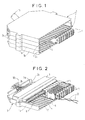
- Figure 1 shows two of the connection modules 1, flat and superimposed, which make up the strip according to the invention. Each of these modules are assigned to the connection of 16 pairs of a multi-pair cable 10 to 16 garters (not shown).
- the strip has 16 modules similar superimposed and is thus assigned to cable 10 of 256 pairs, while having the same dimensions as the known strips 128 pairs.
- Each module 1 consists of a box designated by this reference 1, which is formed by an upper part 1a and a lower part 1b, substantially similar and assembled to each other, and which is equipped internally as described below.
- This box is made of plastic material insulating. It has a narrow and fully open front face 2a and openings rear 2b, 2c, on its rear and side faces.
- each module 1 is equipped internally from a prewired rear connector 3, which is fixedly mounted substantially in a rear half by providing a free rear space 2d for the 10a pairs prewired on this connector and received through one of the rear openings 2b or 2c. It is provided with guides 4, facing each other on the upper and lower walls of its front half and is equipped with connectors front 5 of garter mounted on these guides. These individual connectors front are movable between a position inserted in the rear connector and an unplugged position.
- the rear connector 3 prewired to the pairs 10a is a high connector density of known type, such as HE-12. It has two rows of Compact insulation displacement contacts, defining two rows of connection points and front connection 6, in line with the open front face of the module 1.
- This high density connector 3 prewired to pairs and used in each slider modules, makes the modules and the resulting slider high density or capacity, without increasing dimensions.
- the connectors front 5 of garters are adapted to connectors 3 and provided with contacts space-saving interiors, which are broadly similar to those of connector 3 and are described below.
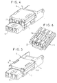
- any of the individual jumper connectors 5 are described in referring to FIG. 2 and more particularly FIG. 3. It includes a basic insulating body 7 having a scalloped face, two contacts identical 8 and a possible third analog contact retained side by side in the notched face of the base support, and a push-button 9 attached and retained on a middle portion of the notched face of the base support.
- the connector 5 thus produced is flat. He went up by his slices of thin between the guides 4 of the front part of one of the modules 1. It it follows that the connector pusher in place in the module or box 1 is parallel to the small side faces of the cabinet and is said to be lateral on this connector in place in the cabinet.
- Contacts 8 and possible other contact are housed between ribs 7a on the notched face and are retained in front through channels such as 11 and rear such as 12 of the base body. These front channels 11 are used for tests, the rear channels allow the passage of contacts for plugging the two contacts 8 into two connection points superimposed 6 of the rear connector 3.
- Two rear branches 7b provided on the basic body protects the parts of the contacts beyond the channels back. They are received elastically on the rear connector, when the connector 5 is plugged into it.
- Guides 14a on the edges of the base body and 14b on the pusher 9 are complementary to the guides 4 in the front part of the module 1, for the connector guide 5.
- Each of the contacts 8 is made for cutting and folding a strip initially flat metallic. It thus essentially presents a flat base longitudinal 13, a front plug 15 of the clamp type on the front end part from the base, a flat rear pin 16, transverse to the base and projecting from the rear end of the latter, and two central self-stripping forks 17a, 17b transverse to base 13 and obtained by folding the two edges of the initial strip. These two insulation displacement forks allow connection at two points on one of the two wires of a jumper in contact 8.
- the pusher 9 mounted on the base body extends opposite the two insulation displacement forks of the contacts 8 housed therein. It presents two holding positions on the basic body, i.e. a position not fully depressed and a fully depressed position. These positions are defined by two staggered sets of lugs 18a and 18b on the edges of the body of base and by a hooking edge 19a of an interior window 19 on each lateral parts of the pusher. These two positions are illustrated in the Figures 4 and 5, the aforementioned provisions for this purpose being in turn visible more precisely in Figures 3 and 6.
- This pusher 9 has three front channels 20 for the entry of two jumper wires in the pusher and a possible earth wire then connected to a third central contact similar to the two contacts 8 of connector 5.
- wires into the pusher 9 are connected in the insulation displacement forks of the contacts, with the plunger in the fully depressed position on the basic body, illustrated in figure 5 and produced using a type tool clamp.
- jumper wires 25, without earth wire are shown connected to one of the jumper connectors 5 in FIG. 2. Their connection to the connector 5 is made while the connector is mounted in the module but is in position not plugged into connector 3 of pairs. He could of course be performed while the connector is removed from the module 1.
- These individual jumper connectors 5, fitted with contacts 8 of small footprint and their pusher snapping fully onto the body base 7, are made very flat. They allow a very low mounting pitch in module 1, which corresponds to the mounting pitch of the contacts of the connector 3 of type HE-12, to make module 1 of high density or capacity. They also allow possible tests, via the front channels 11 in the base body giving access to the front plugs of the contacts of the jumper connector. Its use is easy thanks to the front channels provided in the pusher for the introduction of the jumper wires therein, and the lateral retraction of the pusher on the base body during connection of the jumper to the front connector.
Landscapes
- Engineering & Computer Science (AREA)
- Computer Networks & Wireless Communication (AREA)
- Details Of Connecting Devices For Male And Female Coupling (AREA)
- Connection Or Junction Boxes (AREA)
Applications Claiming Priority (2)
| Application Number | Priority Date | Filing Date | Title |
|---|---|---|---|
| FR0009833 | 2000-07-27 | ||
| FR0009833A FR2812461A1 (fr) | 2000-07-27 | 2000-07-27 | Reglette de raccordement haute densite |
Publications (1)
| Publication Number | Publication Date |
|---|---|
| EP1176673A1 true EP1176673A1 (de) | 2002-01-30 |
Family
ID=8852962
Family Applications (1)
| Application Number | Title | Priority Date | Filing Date |
|---|---|---|---|
| EP01401996A Withdrawn EP1176673A1 (de) | 2000-07-27 | 2001-07-25 | Anschlussleiste hoher Dichte |
Country Status (3)
| Country | Link |
|---|---|
| EP (1) | EP1176673A1 (de) |
| CN (1) | CN1336704A (de) |
| FR (1) | FR2812461A1 (de) |
Cited By (4)
| Publication number | Priority date | Publication date | Assignee | Title |
|---|---|---|---|---|
| EP1592265A1 (de) * | 2004-04-29 | 2005-11-02 | Ycl Electronics Co., Ltd. | Modularer Sprach- und Daten-Signalteiler |
| EP1555727A3 (de) * | 2004-01-15 | 2006-07-05 | Tehalit GmbH | Anschlussmodul |
| WO2006069338A3 (en) * | 2004-12-22 | 2006-08-24 | Molex Inc | Connector with improved dual beam contacts |
| EP2088647A3 (de) * | 2008-02-08 | 2011-04-27 | LEONI Kerpen GmbH | Netzwerkmodul, für den Einbau in eine Verteilerperipherie |
Families Citing this family (1)
| Publication number | Priority date | Publication date | Assignee | Title |
|---|---|---|---|---|
| CN108565588B (zh) * | 2017-10-23 | 2019-08-30 | 浙江一舟电子科技股份有限公司 | 一种数据中心铜缆预端接配线架 |
Citations (3)
| Publication number | Priority date | Publication date | Assignee | Title |
|---|---|---|---|---|
| EP0605200A2 (de) * | 1992-12-26 | 1994-07-06 | Sumitomo Wiring Systems, Ltd. | Schneidklemmverbinder |
| EP0609135A1 (de) * | 1993-01-29 | 1994-08-03 | Alcatel Cable Interface | Vorverdrahtete Anschlussklemmleiste |
| DE19535774C1 (de) * | 1995-09-26 | 1996-12-12 | Siemens Ag | Kontaktbauteil für einen Verteiler in einer Telekommunikationsanlage |
-
2000
- 2000-07-27 FR FR0009833A patent/FR2812461A1/fr active Pending
-
2001
- 2001-07-25 EP EP01401996A patent/EP1176673A1/de not_active Withdrawn
- 2001-07-26 CN CN 01124724 patent/CN1336704A/zh active Pending
Patent Citations (3)
| Publication number | Priority date | Publication date | Assignee | Title |
|---|---|---|---|---|
| EP0605200A2 (de) * | 1992-12-26 | 1994-07-06 | Sumitomo Wiring Systems, Ltd. | Schneidklemmverbinder |
| EP0609135A1 (de) * | 1993-01-29 | 1994-08-03 | Alcatel Cable Interface | Vorverdrahtete Anschlussklemmleiste |
| DE19535774C1 (de) * | 1995-09-26 | 1996-12-12 | Siemens Ag | Kontaktbauteil für einen Verteiler in einer Telekommunikationsanlage |
Cited By (4)
| Publication number | Priority date | Publication date | Assignee | Title |
|---|---|---|---|---|
| EP1555727A3 (de) * | 2004-01-15 | 2006-07-05 | Tehalit GmbH | Anschlussmodul |
| EP1592265A1 (de) * | 2004-04-29 | 2005-11-02 | Ycl Electronics Co., Ltd. | Modularer Sprach- und Daten-Signalteiler |
| WO2006069338A3 (en) * | 2004-12-22 | 2006-08-24 | Molex Inc | Connector with improved dual beam contacts |
| EP2088647A3 (de) * | 2008-02-08 | 2011-04-27 | LEONI Kerpen GmbH | Netzwerkmodul, für den Einbau in eine Verteilerperipherie |
Also Published As
| Publication number | Publication date |
|---|---|
| CN1336704A (zh) | 2002-02-20 |
| FR2812461A1 (fr) | 2002-02-01 |
Similar Documents
| Publication | Publication Date | Title |
|---|---|---|
| EP0775375B1 (de) | Anspeisenetzwerk mit niedrigem übersprechen | |
| FR2741204A1 (fr) | Assemblage de connecteur electrique | |
| FR2648628A1 (fr) | Systeme de connecteurs electriques | |
| FR2673050A1 (fr) | Bloc de connexion electrique enfichable et connecteur incorporant un tel bloc. | |
| EP0524115B1 (de) | Kontaktleister, insbesondere für Telefon- oder Datenleitungen | |
| EP0723314B1 (de) | Elektrischer Verbinder | |
| EP0682387A1 (de) | Halteanordnung für einem Gegenstecker | |
| EP1176673A1 (de) | Anschlussleiste hoher Dichte | |
| FR2737941A1 (fr) | Assemblage de jack modulaire electrique | |
| FR2822597A1 (fr) | Connecteur d'usage commun a objets multiples et procede de fabrication du connecteur | |
| FR2489609A1 (fr) | Module de raccordement de conducteurs electriques a connecteurs amovibles | |
| FR2781611A1 (fr) | Piece de contact pour connecteur femelle, et connecteur comportant une telle piece de contact | |
| FR2710462A1 (fr) | Réglette de connexion. | |
| WO2006048530A1 (fr) | Element de bornier et connecteur sans vis | |
| FR2740617A3 (fr) | Connecteur electrique multibroche a plusieurs poles | |
| FR2754943A1 (fr) | Connecteur electrique a verrouillage des bornes de contact | |
| EP0645938B1 (de) | Anschlussleiste mit integrierter Trennung | |
| EP0949718B1 (de) | Verbindungs-/Trenn- modul für elektrische isolierte Leiterpaare | |
| EP0609135B1 (de) | Vorverdrahtete Anschlussklemmleiste | |
| EP0609136B1 (de) | Endverbinder für Schaltadern | |
| FR2724265A1 (fr) | Connecteur electrique modulaire et reglette equipee de tels connecteurs | |
| EP0353137A1 (de) | Transformator | |
| FR2508243A1 (fr) | Agencement de connexion pour connecteur a languettes | |
| EP1199779B1 (de) | Anordnung zur federnden Kontaktierung, insbesondere für ein elektrisches Gerät, sowie diese Anordnung enthaltender elektrischer Steckverbinder | |
| EP0525636B1 (de) | Verbindungsanordnung mit verbesserter Zuverlässigkeit für mehradriges Kabel |
Legal Events
| Date | Code | Title | Description |
|---|---|---|---|
| PUAI | Public reference made under article 153(3) epc to a published international application that has entered the european phase |
Free format text: ORIGINAL CODE: 0009012 |
|
| AK | Designated contracting states |
Kind code of ref document: A1 Designated state(s): AT BE CH CY DE DK ES FI FR GB GR IE IT LI LU MC NL PT SE TR |
|
| AX | Request for extension of the european patent |
Free format text: AL;LT;LV;MK;RO;SI |
|
| 17P | Request for examination filed |
Effective date: 20020730 |
|
| AKX | Designation fees paid |
Free format text: AT BE CH CY DE DK ES FI FR GB GR IE IT LI LU MC NL PT SE TR |
|
| STAA | Information on the status of an ep patent application or granted ep patent |
Free format text: STATUS: THE APPLICATION HAS BEEN WITHDRAWN |
|
| 18W | Application withdrawn |
Effective date: 20030312 |