EP1176684B1 - Boîte de connexion multi-média - Google Patents
Boîte de connexion multi-média Download PDFInfo
- Publication number
- EP1176684B1 EP1176684B1 EP01117925A EP01117925A EP1176684B1 EP 1176684 B1 EP1176684 B1 EP 1176684B1 EP 01117925 A EP01117925 A EP 01117925A EP 01117925 A EP01117925 A EP 01117925A EP 1176684 B1 EP1176684 B1 EP 1176684B1
- Authority
- EP
- European Patent Office
- Prior art keywords
- connection
- multimedia
- connection box
- box
- shield
- Prior art date
- Legal status (The legal status is an assumption and is not a legal conclusion. Google has not performed a legal analysis and makes no representation as to the accuracy of the status listed.)
- Expired - Lifetime
Links
- 239000002184 metal Substances 0.000 claims abstract description 13
- 238000004891 communication Methods 0.000 claims description 22
- 238000002788 crimping Methods 0.000 claims description 2
- 238000004519 manufacturing process Methods 0.000 claims description 2
- 230000002093 peripheral effect Effects 0.000 claims 1
- 238000009434 installation Methods 0.000 description 11
- 230000005540 biological transmission Effects 0.000 description 7
- 238000005452 bending Methods 0.000 description 4
- 238000005516 engineering process Methods 0.000 description 4
- 238000013461 design Methods 0.000 description 3
- 238000011161 development Methods 0.000 description 3
- 230000018109 developmental process Effects 0.000 description 3
- 230000006978 adaptation Effects 0.000 description 2
- 238000009435 building construction Methods 0.000 description 1
- 238000006243 chemical reaction Methods 0.000 description 1
- 239000011248 coating agent Substances 0.000 description 1
- 238000000576 coating method Methods 0.000 description 1
- 230000000295 complement effect Effects 0.000 description 1
- 239000004020 conductor Substances 0.000 description 1
- 230000001419 dependent effect Effects 0.000 description 1
- 230000000694 effects Effects 0.000 description 1
- 229920001971 elastomer Polymers 0.000 description 1
- 239000000806 elastomer Substances 0.000 description 1
- 238000010292 electrical insulation Methods 0.000 description 1
- 230000036039 immunity Effects 0.000 description 1
- 208000015181 infectious disease Diseases 0.000 description 1
- 230000002458 infectious effect Effects 0.000 description 1
- 238000003780 insertion Methods 0.000 description 1
- 230000037431 insertion Effects 0.000 description 1
- 238000009413 insulation Methods 0.000 description 1
- 239000012212 insulator Substances 0.000 description 1
- 239000000463 material Substances 0.000 description 1
- 230000006855 networking Effects 0.000 description 1
- 230000000284 resting effect Effects 0.000 description 1
- 238000012216 screening Methods 0.000 description 1
- 230000008054 signal transmission Effects 0.000 description 1
- 230000007704 transition Effects 0.000 description 1
Images


Classifications
-
- H—ELECTRICITY
- H02—GENERATION; CONVERSION OR DISTRIBUTION OF ELECTRIC POWER
- H02G—INSTALLATION OF ELECTRIC CABLES OR LINES, OR OF COMBINED OPTICAL AND ELECTRIC CABLES OR LINES
- H02G3/00—Installations of electric cables or lines or protective tubing therefor in or on buildings, equivalent structures or vehicles
- H02G3/02—Details
- H02G3/08—Distribution boxes; Connection or junction boxes
- H02G3/081—Bases, casings or covers
- H02G3/083—Inlets
-
- H—ELECTRICITY
- H01—ELECTRIC ELEMENTS
- H01R—ELECTRICALLY-CONDUCTIVE CONNECTIONS; STRUCTURAL ASSOCIATIONS OF A PLURALITY OF MUTUALLY-INSULATED ELECTRICAL CONNECTING ELEMENTS; COUPLING DEVICES; CURRENT COLLECTORS
- H01R24/00—Two-part coupling devices, or either of their cooperating parts, characterised by their overall structure
- H01R24/38—Two-part coupling devices, or either of their cooperating parts, characterised by their overall structure having concentrically or coaxially arranged contacts
- H01R24/40—Two-part coupling devices, or either of their cooperating parts, characterised by their overall structure having concentrically or coaxially arranged contacts specially adapted for high frequency
- H01R24/52—Two-part coupling devices, or either of their cooperating parts, characterised by their overall structure having concentrically or coaxially arranged contacts specially adapted for high frequency mounted in or to a panel or structure
- H01R24/525—Outlets
Definitions
- the present invention relates to a junction box according to the preamble of claim 1, and a shield terminal element according to claim 9 and a communication module according to claim 13 for use with this junction box and the use of a communication module with this junction box.
- junction boxes are from telecommunications and data transmission technology (See DE-C1-4234451 ), serve all forms of data communication such as video, audio, computer and telephone transmission and are used, inter alia, as surface-mounted or flush-mounted boxes in building construction.
- Both analog devices and ISDN devices for example for telephone, fax, modem, personal computer, etc., can be connected to these Socket Outlets to an S-BUS, which is terminated at its one end (customer side) with a terminating resistor of, for example, 100 ohms and at its other end (provider side) to a network termination device (NT + 2ab) is connected.
- This network termination device is in turn connected via a control box or exchange distributor with the local center.
- connection boxes for telecommunication or data transmission have, for example, 4-pole plug inserts, A6 inserts (6-pin), RJ45 inserts (8-pin) or RJ11 inserts (4-pin or 6-pin).
- These plug and socket outlets can be designed in a flush-mounted design and include a base plate with one or two inserts, a mounting plate and a cover.
- a flush-mounted inlet box is preferably provided, which usually has a substantially round cross section with an inner diameter of about 58 mm or a substantially rectangular Cross section with side lengths of about 58 mm x 58 mm.
- the plug and socket can also be designed in a surface-mounted version and includes, depending on the use, a cap or a cover frame with a front panel.
- junction boxes are also known from the television and radio engineering, ie HF technology, and in particular from the installations of coaxial cable networks.
- coaxial antenna sockets each have a shielded cable connection for a television and a radio receiver (IEC socket and IEC plug).
- IEC socket and IEC plug Such a junction box is for example from the DE 198 35 631 known.
- these are equipped with additional connections for a backward-compatible data communication, in particular an Internet connection and / or a telephone socket.
- Such multimedia junction boxes are preferably used in home and small office environments, among others. in apartments and houses, administrative buildings, hospitals and catering establishments. Electronic devices such as telephones, answering machines, televisions, video recorders and faxes, computers and Internet devices are increasingly being used there. Another development is in the use of remote-controlled household appliances, home security devices, lighting fixtures, etc. The cabling and networking of all these devices and installations requires considerable effort because separate doses must be installed for each of these services or applications.
- junction boxes that meet these needs in part, are already known in the art. These junction boxes have a metallic can body respectively a mounting element, in the bottom part of which is required for signal transmission electrical circuit. Sockets for the shielded and unshielded connectors, as well as terminals for attaching the coaxial cables to be connected, are mounted on this base part.
- the majority of the floor area or cross-sectional area of the junction box is required for the shielded coaxial connections, which is why the space above the floor space fitted with these coaxial connections must be used for the additional connection elements for communication technology. This leads to an undesirably high structure for the arrangement of the connectors and therefore to an undesirably large installation depth for the entire junction box.
- the main object of the present invention is to provide a junction box, which allows to use communication modules of known type in the simplest way and in combination with this can.
- a junction box with the features of claim 1 and in particular by a junction box, which comprises a closed metallic housing in which at least one coaxial connector is integrated, which metallic housing has a base area, the maximum half of the cross-sectional area claimed the junction box and which metallic housing is provided with a first adapter part for the attachment of at least one communication module.
- the cross-sectional area of the junction box is essentially limited by the space provided by the inlet box. Normally, this cross-sectional area will correspond to that of a standard installation box. It is therefore to be understood that the cross-sectional area of the junction box is not understood below to mean the cross-section of the space occupied by the modules used, but rather the cross-sectional area of the space usable for such modules.
- the insert modules for communication technology or the communication modules are arranged next to the metallic housing and, essentially on the same level.
- the metallic housing for the production of a mechanical and electrical interface is provided with at least one connection point for the tangential reception of a screen connection element.
- the advantages of the multimedia junction box according to the invention are immediately apparent to the person skilled in the art.
- these cans can be easily, quickly and inexpensively installed thanks to their large modularity and allow a variety of arbitrary arrangements to be made without much effort, so that the inventive multimedia junction box is very easy to install or user-friendly.
- an extension of the application possibilities can be achieved without much effort.
- this can simplifies the expansion of existing installations and enables optimal adaptation to customer needs.
- connection cables can be connected tangentially to the box, wherein it is meant that the connection cables are fed in a direction substantially tangential to the circumferential direction of the box direction, so that these cables of the box are fed under a maximum bending radius.
- the inventive arrangement leads to junction boxes with low installation depth, which is technically desirable to avoid, for example, sound and thermal bridges.
- FIG. 1 This consists essentially of a metallic mounting element 2 with a mounting collar 8 and a bottom part 3.
- the connection electronics respectively the electrical circuit for the connection is housed.
- Koaxialan gleichbuchsen 4, 5 are attached.
- a connection terminal 6 is provided, to which the required coaxial cables are connected.
- a socket 7 is also set up for the transmission of communication signals. This socket 7 is mounted substantially on this junction box and thus increases their overall height.
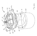
- FIG. 2 shows a view of a possible embodiment of an inventive multimedia junction box 11.
- a metallic housing 10 by means of three screws 12, 12 ', 12''attached to a mounting plate 9.
- three sockets 14, 15, 16 for the connection of shielded coaxial cables.
- a tangentially arranged shield connection element 17 allows the junction box with the house distribution system connect.
- This shield connection element 17 is designed such that it can be crimped on the one hand to a coaxial cable, and on the other hand in the metallic housing 10 can be inserted, so that this can make an electrically and mechanically stable connection with the metallic housing 10.
- this shield connection element 17 is arranged substantially tangentially to the circumferential direction of the metallic housing 10 on the box, so that a guide of the coaxial cable is possible with a maximum possible bending radius, ie that the cable has no kinks, respectively no places where the connected cable has to be bent in such a way that it falls below the permitted bending radius.
- a first adapter part 18, to which a communication module 19 can be fastened by means of a second adapter part 20, is attached to the metallic housing 10.
- This in FIG. 2 illustrated communication module comprises a terminal block 21 and two suitable for the data and communication RJ45 connection or contact sockets 22, 23.
- the inventive junction box 11 has a much lower overall height, with the overall height of the in FIG. 1 is meant with respect to the viewing plane in the vertical direction extending height.
- the contact socket 7 for the data and communication transmission offset in the vertical direction or above the sockets 4, 5 is arranged for the coaxial cable
- the inventive junction box 11 the contact sockets 19, 22 and the sockets 14, 15, 16 in essential at the same level lying, or lying side by side.
- This inventive arrangement makes it possible to create a multimedia junction box with a low total height of, for example, less than 30 mm, for example, 28.5 mm.
- Such a configuration has the particular advantage that the inventive multimedia junction box for installation in a standardized flush-mounted inlet box with 58 mm diameter or side length can be installed.
- the inventive multimedia junction box can be used in combination with existing, standardized inlet boxes.
- this is equipped with strain relief elements 24, 25. These strain relief elements 24, 25 can be moved transversely to the mounting plate 9 and are latched into this.
- FIG. 3 shows the inventive multimedia junction box 11 with an attached front panel 26 and a matching cover frame 27.
- This embodiment is suitable for flush mounting. It is understood that instead of the cover frame 27 also suitable for the surface mounting cap can be used, or that instead of a substantially square shaped front panel 26 and a circular front plate, respectively cylindrical cap can be used.
- FIG. 3 again clearly shows that connected to the metallic housing 10, for example, plugged sockets 22 and 23 for the data and communication transmission are in substantially the same plane as the integrated in the metallic housing 10 coaxial sockets 14, 15, 16th
- FIG. 4 shows the inventive multimedia junction box 11 in an exploded view.
- the inventively designed metallic housing 10 in the bottom part of the required electronic and / or electrical circuit can be accommodated and in the inner part of the desired coaxial sockets 14, 15, 16 are integrated.
- the electronic or electrical circuit is shielded with a shield plate which forms the bottom of the metallic housing 10.
- This metallic housing 10 has at least one connection point 28 into which a shield connection element 17 can be inserted.
- the edge of the connection point 28 is designed such that with a ball joint shaped contact sleeve 29, a good mechanical and electrical connection can be made.
- the shield connection element 17 is provided on the cable side with a metallic sleeve 30 which is connected to the coaxial cable 31.
- a metallic sleeve 30 which is connected to the coaxial cable 31.
- an A-contact 32 is arranged, in which the soul 33 of the coaxial cable 31 can be inserted.
- the housing 10 has a base surface which occupies a maximum of half the cross-sectional or bottom surface of a standard installation box.
- the fastening plate 9 carries two strain relief elements 24, 25 which hold the shield connection elements 17 on the housing 10 in the locked state. It is understood that the mounting plate 9 is provided with openings 34 and 35 to mount them in a known manner.
- FIG. 5 shows a shield connection element 17 designed according to the invention with a core 33, which is connected to an A-contact 32.
- the shield connection element on the cable side an electrically conductive, in particular metallic crimp sleeve 30, which can be crimped onto an electrically conductive shield, in particular a metallic braid shield 38 of a coaxial cable 31.
- this shield connection element 17 has a metallic contact sleeve 29 which can be inserted into the connection point 28 of the metallic housing 10.
- the shape of this contact sleeve 29 is complementary to the shape of the connection point 28. This ensures a frictional and positive mechanical and a shielded electrical connection.
- the A-contact 32 is funnel-shaped on the cable side in order to be able to receive the core 33 of the coaxial cable 31 in a frictionally engaged manner.
- the contact sleeve 29 is provided with slots 36 to produce a resilient, non-positive and positive connection between the contact sleeve 29 and junction 28.
- the crimp barrel 30 may be slotted to facilitate crimping.
- a neck portion 37 is provided, via which the strain relief element 24 or 25 can be pushed.
- the shield connection element 17 is held in its position, respectively relieved of any tensile forces. It is understood that the shield connection element 17 does not necessarily need to be held with special strain relief elements 24, but can be secured to the metallic housing 10 by known means, in particular cable ties.
- FIG. 6 shows a further embodiment of a shield connection element 17, which, in contrast to the in FIG. 5 Shield connection element 17, a threaded sleeve 40 which is fixedly or flexibly connected to the contact sleeve 29, wherein the threaded sleeve 40 can be screwed onto the braid shield 38, so that an electrical screening effect between the braid shield 38 and the contact sleeve 29 is ensured.
- the braid shield 38 must be previously exposed and is advantageously covered over the outer insulation.
- FIG. 7 shows that in FIG. 6 Shroud connecting element 17 with contact sleeve 29, neck portion 37, threaded sleeve 40, braid shield 38 and cable sheath 41.
- the core 33 of the coaxial cable 31 is engaged by a U-shaped, prestressed, electrically conductive spring contact 42.
- This spring contact 42 is located downstream of the connection point 28 of the metallic housing 10.
- One of the legs of the U-shaped spring contact 42 is fixed to a base plate 43 (PCB or PWB).
- the gap-shaped opening of the spring contact 42 aligned in the illustrated arrangement with respect to the contact sleeve 29 is arranged with respect to the connection point 28 in such a way that the core 33 slides into the slot 28 during insertion of the shield connection element 17, so that a frictional and non-positive fit occurs , low-ohmic connection between the soul 33 and the spring contact 42 is formed.
- the spring contact 42 is preferably made of metal.
- the core 33 consists of a soft and the spring contact 42 of a relatively hard material. The high spring force of the spring contact 42 allows an electrical connection to the soul 33 with a very low contact resistance.
- FIG. 8 shows a further embodiment of a junction box 11, which comprises a metallic housing 10 with coaxial sockets 14, 15, 16, adapter part 18 and a mounting plate 9.
- a junction box 11 which comprises a metallic housing 10 with coaxial sockets 14, 15, 16, adapter part 18 and a mounting plate 9.
- port box 11 shown on the contact sleeve 29 and the correspondingly adapted configured connection point 28 are omitted by the stripped coaxial cable 31 is inserted directly into the connection point 28.
- the core 33 is exposed on the front side of the coaxial cable 31 and the braid shield 38 is placed on the surface of the outer jacket 41 resting.
- Behind the junction 28 is the in FIG. 7 arranged spring contact 42, in which the soul 33 is introduced.
- the junction box 11 includes a pivotally mounted in a bearing 46 fastening means 44, in particular a clamp, with screw 45 and ribs 47.
- the coaxial cable 31 is now mounted in the junction box 11 so that the soul 33 is inserted sufficiently deep into the spring contact 42 and the braid shield 38 to lie in the region of the ribs 47 comes.
- the fastener 44 is pivoted downwardly and fixedly connected to the metallic housing 10 by means of the screw 45, so that the coaxial cable 31 is slightly squeezed by the ribs 47, thereby forming a mechanical strain relief.
- the space in front of the connection point 28 may be provided with an electrically conductive shield 48 in order to better shield the transition point of the coaxial cable 31 against interference signals.
- the shield 48 is advantageously formed of a thin sheet metal, but may also consist of another electrical conductor, for example of an electrically conductive elastomer.
- the screw 45 can be released again at any time and the fastening means 44 can be opened so that the coaxial cable 31 can be replaced.
- An advantage of in FIG. 8 illustrated junction box 11 is the fact that for connecting the coaxial cable 31 no additional aids are required. It is sufficient to expose the core 33 and expose the braid shield 38 such that a conductive connection to the housing 10 can be formed.
- the connection point 28 is arranged in the housing 10 in such a way that the coaxial cable 31 can be fed to it substantially tangentially to the circumferential direction of the housing 10.
- FIG. 8 illustrated junction box 11 Another advantage of in FIG. 8 illustrated junction box 11 can be seen in the fact that coaxial cable 11 with different diameters can be connected without additional aids.
- FIG. 8 illustrated junction box 11 has two separate connections, each for a separate coaxial cable 31st
- FIG. 9 shows the two fixedly connected to the base plate 43 of the housing 10 spring contacts 42.
- the two Fastening means 44 are pivotally mounted in the metallic housing 10 via bearing pins 49 in the pivoting direction S.
- Each fastener 44 has an opening pin 50 which is arranged with respect to the spring contact 42 and configured adapted that this opening pin 50 engages when folding the fastener 44 in the space of the U-shaped spring contact 42 and thereby opens the spring contact, so that the soul 33 can be inserted without or with very little force in the spring contact 42 or pulled out of this.
- the in FIG. 9 illustrated opening pin 50 thus has the advantage that the soul 33, even if the spring contact 42 has a very high spring force, with little effort in the metallic housing is inserted.
- the opening pin 50 can also be electrically insulated and consist, for example, of an insulator or have an insulating surface coating.
- FIG. 10 shows the junction box 11 according to FIG. 8 together with a flush-mounted inlet box 51 with internal diameter D.
- the coaxial cable 31 is arranged substantially helically extending in the flush-mounted inlet box 51 and opens in a substantially tangential direction in the metallic housing 10 of the junction box 11.
- This arrangement has the advantage that the connection box 11 can be mounted with a relatively long coaxial cable section to be arranged in the flush-mounted inlet box 51, so that the connection box 11 is very comfortable, safe and can be mounted in a short time.
- the inner diameter D is preferably about 58 mm.
Landscapes
- Engineering & Computer Science (AREA)
- Architecture (AREA)
- Civil Engineering (AREA)
- Structural Engineering (AREA)
- Coupling Device And Connection With Printed Circuit (AREA)
- Details Of Connecting Devices For Male And Female Coupling (AREA)
- Liquid Crystal (AREA)
- Two-Way Televisions, Distribution Of Moving Picture Or The Like (AREA)
Claims (14)
- Boîte de raccordement multimédia (11) comprenant une partie de fond de boîte (3) avec au moins un point de raccordement (28) pour la réception d'un câble coaxial (31) et avec au moins une douille de raccordement coaxiale (14, 15, 16), caractérisée par le fait que la boîte de raccordement (11) comprend un boîtier métallique fermé (10) dans lequel au moins une douille de raccordement coaxiale (14, 15, 16) est intégrée, le boîtier métallique (10) ayant une surface qui représente au maximum la moitié de l'aire de la section de la boîte de raccordement (11) et le boîtier métallique (10) étant pourvu d'un premier élément adaptateur (18) pour le raccordement d'au moins un module de communication (19).
- Boîte de raccordement multimédia selon la revendication 1, caractérisée par le fait que le boîtier métallique (10) comprend le point de raccordement (28) pour l'établissement d'une interface métallique et/ou électrique.
- Boîte de raccordement multimédia selon la revendication 2, caractérisée par le fait que le point de raccordement (28) est situé dans le boîtier métallique (10) de manière à ce qu'un câble coaxial (31) puisse être connecté à ce point de raccordement (28) dans une direction essentiellement tangentielle par rapport à la direction circonférentielle du boîtier métallique (10).
- Boîte de raccordement multimédia selon l'une des revendications précédentes, caractérisée par le fait que la boîte de raccordement (11) comprend au moins un module de communication de données (19) dont la surface représente au maximum la moitié de l'aire de la section de la boîte de raccordement (11).
- Boîte de raccordement multimédia selon l'une des revendications précédentes, caractérisée par le fait que cette boîte comprend une plaque de fixation (9) qui est pourvue d'au moins un élément de décharge de traction (24, 25).
- Boîte de raccordement multimédia selon l'une des revendications précédentes, caractérisée par le fait qu'un contact élastique (42) est situé dans le boîtier métallique (10).
- Boîte de raccordement multimédia selon la revendication 6, caractérisée par le fait qu'un moyen de fixation (44) monté de manière pivotante dans le boîtier (10) est situé devant le point de raccordement (28).
- Boîte de raccordement multimédia selon la revendication 7, caractérisée par le fait que le moyen de fixation (44) comprend une broche d'ouverture (50) qui est disposée de telle façon par rapport au contact élastique (42) que la broche d'ouverture (50) ouvre le contact élastique (42) lorsque le moyen de fixation (44) pivote.
- Elément de raccordement de blindage (17) destiné à être utilisé avec une boîte de raccordement multimédia (11) selon la revendication 1, caractérisé par le fait qu'il est exécuté de manière à coopérer mécaniquement et électriquement avec le point de raccordement (28) de la boîte de raccordement (11).
- Elément de raccordement de blindage selon la revendication 9, caractérisé par le fait qu'il est pourvu, sur le côté de la boîte, d'une douille de contact électroconductrice (29) grâce à laquelle le contact mécanique et électrique avec le point de raccordement (28) peut être établi.
- Elément de raccordement de blindage selon l'une des revendications 9 ou 10, caractérisé par le fait qu'il est pourvu, sur le côté du câble, d'une douille de sertissage électroconductrice (30) qui peut être sertie sur un blindage, notamment un blindage tressé (38) d'un câble coaxial (31).
- Elément de raccordement de blindage selon l'une des revendications 9 ou 10, caractérisé par le fait qu'il est pourvu, sur le côté du CABLE, d'une douille (40), notamment d'une douille filetée, qui est pourvue d'une liaison électrique avec le blindage du câble coaxial (31) et qui est reliée à la douille de contact métallique (29).
- Module de données et de communication (19) destiné à être utilisé avec une boîte de raccordement multimédia (11) selon la revendication 1, caractérisé par le fait qu'il est pourvu d'un second élément adaptateur (20) qui coopère avec le premier élément adaptateur (18) du boîtier métallique (10).
- Utilisation d'un module de données et de communication (19) selon la revendication 13 dans une boîte de raccordement multimédia (11) selon la revendication 1.
Applications Claiming Priority (2)
| Application Number | Priority Date | Filing Date | Title |
|---|---|---|---|
| CH14982000 | 2000-07-28 | ||
| CH14982000 | 2000-07-28 |
Publications (2)
| Publication Number | Publication Date |
|---|---|
| EP1176684A1 EP1176684A1 (fr) | 2002-01-30 |
| EP1176684B1 true EP1176684B1 (fr) | 2010-10-20 |
Family
ID=4565522
Family Applications (1)
| Application Number | Title | Priority Date | Filing Date |
|---|---|---|---|
| EP01117925A Expired - Lifetime EP1176684B1 (fr) | 2000-07-28 | 2001-07-24 | Boîte de connexion multi-média |
Country Status (4)
| Country | Link |
|---|---|
| EP (1) | EP1176684B1 (fr) |
| AT (1) | ATE485614T1 (fr) |
| DE (1) | DE50115665D1 (fr) |
| DK (1) | DK1176684T3 (fr) |
Families Citing this family (3)
| Publication number | Priority date | Publication date | Assignee | Title |
|---|---|---|---|---|
| CH703304B1 (de) | 2010-06-01 | 2014-03-14 | Zidatech Ag | Anschlussdose. |
| DE102014217481A1 (de) * | 2014-09-02 | 2016-03-03 | Fränkische Rohrwerke Gebr. Kirchner Gmbh & Co. Kg | Anschlusseinheit |
| DE102017114982B3 (de) | 2017-07-05 | 2018-10-25 | Ecad Electronic Components And Devices Gmbh | Set aus Multimediadose und Umschaltstift |
Family Cites Families (3)
| Publication number | Priority date | Publication date | Assignee | Title |
|---|---|---|---|---|
| DE8708237U1 (de) * | 1987-06-11 | 1987-08-06 | A. & H. Meyer GmbH Leuchten und Büroelektrik, 32694 Dörentrup | Steckdosenbox |
| CA2017589C (fr) * | 1990-05-25 | 1995-01-31 | William Nattel | Prise electrique murale d'alimentation et de communication |
| DE4234451C1 (de) * | 1992-10-13 | 1994-04-21 | Metz Albert Blumberger Tel | Anschlußdose für abgeschirmte Kabel, insbesondere für Datenübertragungskabel |
-
2001
- 2001-07-24 EP EP01117925A patent/EP1176684B1/fr not_active Expired - Lifetime
- 2001-07-24 DK DK01117925.6T patent/DK1176684T3/da active
- 2001-07-24 DE DE50115665T patent/DE50115665D1/de not_active Expired - Lifetime
- 2001-07-24 AT AT01117925T patent/ATE485614T1/de active
Also Published As
| Publication number | Publication date |
|---|---|
| DE50115665D1 (de) | 2010-12-02 |
| EP1176684A1 (fr) | 2002-01-30 |
| DK1176684T3 (da) | 2011-01-24 |
| ATE485614T1 (de) | 2010-11-15 |
Similar Documents
| Publication | Publication Date | Title |
|---|---|---|
| EP0809331B1 (fr) | Connecteur à fiche multipolaire ayant une prise avec au moins une fiche pour le raccordement électrique et mécanique des conducteurs électriques | |
| DE69302542T2 (de) | Zugriffstecker für Querverbindereinrichtung | |
| DE3650244T2 (de) | Klinkensteckvorrichtung. | |
| EP1105947B1 (fr) | Dispositif de transmission de messages par un reseau d'alimentation en courant basse tension et element intermediaire | |
| DE102009021594A1 (de) | Elektrischer Steckverbinder und elektrische Steckverbindung | |
| EP0700126B1 (fr) | Fiche pour câble multiconducteur | |
| DE3752212T2 (de) | Abgeschirmter Verbinder für Datenübertragung | |
| EP2417675B1 (fr) | Boîtier de système à fiches pour câbles multiconducteurs | |
| EP0447660A1 (fr) | Dispositif de connexion pour câbles de transmission de données, en particulier pour un réseau de données | |
| EP1176684B1 (fr) | Boîte de connexion multi-média | |
| DE10053843C1 (de) | Ethernet Steckverbindung mit zusätzlichen Kontakten zur Spannungsversorgungseinspeisung | |
| EP0865119B1 (fr) | Boíte de connexion pour un système de distribution | |
| DE19721532C2 (de) | Kombinations- Antennensteckdose zum Einbau in eine standardisierte Aufputz- oder Unterputzdose | |
| DE3723987C2 (fr) | ||
| EP2568544B1 (fr) | Prise multimédia | |
| EP0838881B1 (fr) | Prise d'antenne | |
| DE10339570B4 (de) | Antennensteckdose | |
| DE4345217C2 (de) | Anschlußkabel zur Bildung einer Anschlußeinrichtung für ein Datennetz | |
| DE19608876C2 (de) | Geschirmte Anschlußdose | |
| DE29709594U1 (de) | Antennensteckdose | |
| DE4229705C2 (de) | Steckvorrichtung für hochfrequente Signale | |
| EP1249898A2 (fr) | Connecteur coaxial à enclenchement audible à la mise en contact électrique | |
| DE10121424C2 (de) | Anschlußeinheit für Telekommunikations- und Datennetze | |
| EP0762546A2 (fr) | Boîte de raccordement pour appareillage électrique | |
| EP0871251B1 (fr) | Boíte de verrouillage |
Legal Events
| Date | Code | Title | Description |
|---|---|---|---|
| PUAI | Public reference made under article 153(3) epc to a published international application that has entered the european phase |
Free format text: ORIGINAL CODE: 0009012 |
|
| AK | Designated contracting states |
Kind code of ref document: A1 Designated state(s): AT BE CH CY DE DK ES FI FR GB GR IE IT LI LU MC NL PT SE TR |
|
| AX | Request for extension of the european patent |
Free format text: AL;LT;LV;MK;RO;SI |
|
| 17P | Request for examination filed |
Effective date: 20020718 |
|
| AKX | Designation fees paid |
Free format text: AT BE CH CY DE DK ES FI FR GB GR IE IT LI LU MC NL PT SE TR |
|
| GRAP | Despatch of communication of intention to grant a patent |
Free format text: ORIGINAL CODE: EPIDOSNIGR1 |
|
| GRAS | Grant fee paid |
Free format text: ORIGINAL CODE: EPIDOSNIGR3 |
|
| GRAA | (expected) grant |
Free format text: ORIGINAL CODE: 0009210 |
|
| AK | Designated contracting states |
Kind code of ref document: B1 Designated state(s): AT BE CH CY DE DK ES FI FR GB GR IE IT LI LU MC NL PT SE TR |
|
| REG | Reference to a national code |
Ref country code: GB Ref legal event code: FG4D Free format text: NOT ENGLISH |
|
| REG | Reference to a national code |
Ref country code: CH Ref legal event code: EP Ref country code: CH Ref legal event code: NV Representative=s name: HANS ULRICH SEIFERT SEIFERT & PARTNER |
|
| REG | Reference to a national code |
Ref country code: IE Ref legal event code: FG4D Free format text: LANGUAGE OF EP DOCUMENT: GERMAN |
|
| REF | Corresponds to: |
Ref document number: 50115665 Country of ref document: DE Date of ref document: 20101202 Kind code of ref document: P |
|
| REG | Reference to a national code |
Ref country code: DK Ref legal event code: T3 |
|
| REG | Reference to a national code |
Ref country code: NL Ref legal event code: T3 |
|
| REG | Reference to a national code |
Ref country code: SE Ref legal event code: TRGR |
|
| REG | Reference to a national code |
Ref country code: IE Ref legal event code: FD4D |
|
| PG25 | Lapsed in a contracting state [announced via postgrant information from national office to epo] |
Ref country code: PT Free format text: LAPSE BECAUSE OF FAILURE TO SUBMIT A TRANSLATION OF THE DESCRIPTION OR TO PAY THE FEE WITHIN THE PRESCRIBED TIME-LIMIT Effective date: 20110221 |
|
| PG25 | Lapsed in a contracting state [announced via postgrant information from national office to epo] |
Ref country code: GR Free format text: LAPSE BECAUSE OF FAILURE TO SUBMIT A TRANSLATION OF THE DESCRIPTION OR TO PAY THE FEE WITHIN THE PRESCRIBED TIME-LIMIT Effective date: 20110121 |
|
| PG25 | Lapsed in a contracting state [announced via postgrant information from national office to epo] |
Ref country code: ES Free format text: LAPSE BECAUSE OF FAILURE TO SUBMIT A TRANSLATION OF THE DESCRIPTION OR TO PAY THE FEE WITHIN THE PRESCRIBED TIME-LIMIT Effective date: 20110131 Ref country code: IE Free format text: LAPSE BECAUSE OF FAILURE TO SUBMIT A TRANSLATION OF THE DESCRIPTION OR TO PAY THE FEE WITHIN THE PRESCRIBED TIME-LIMIT Effective date: 20101020 |
|
| PLBE | No opposition filed within time limit |
Free format text: ORIGINAL CODE: 0009261 |
|
| STAA | Information on the status of an ep patent application or granted ep patent |
Free format text: STATUS: NO OPPOSITION FILED WITHIN TIME LIMIT |
|
| 26N | No opposition filed |
Effective date: 20110721 |
|
| REG | Reference to a national code |
Ref country code: DE Ref legal event code: R097 Ref document number: 50115665 Country of ref document: DE Effective date: 20110721 |
|
| PG25 | Lapsed in a contracting state [announced via postgrant information from national office to epo] |
Ref country code: IT Free format text: LAPSE BECAUSE OF FAILURE TO SUBMIT A TRANSLATION OF THE DESCRIPTION OR TO PAY THE FEE WITHIN THE PRESCRIBED TIME-LIMIT Effective date: 20101020 |
|
| PG25 | Lapsed in a contracting state [announced via postgrant information from national office to epo] |
Ref country code: MC Free format text: LAPSE BECAUSE OF NON-PAYMENT OF DUE FEES Effective date: 20110731 |
|
| GBPC | Gb: european patent ceased through non-payment of renewal fee |
Effective date: 20110724 |
|
| REG | Reference to a national code |
Ref country code: FR Ref legal event code: ST Effective date: 20120330 |
|
| PG25 | Lapsed in a contracting state [announced via postgrant information from national office to epo] |
Ref country code: FR Free format text: LAPSE BECAUSE OF NON-PAYMENT OF DUE FEES Effective date: 20110801 |
|
| REG | Reference to a national code |
Ref country code: CH Ref legal event code: NV Representative=s name: THOMAS DAUB |
|
| REG | Reference to a national code |
Ref country code: DE Ref legal event code: R082 Ref document number: 50115665 Country of ref document: DE Representative=s name: DAUB UND KOLLEGEN, DE Ref country code: DE Ref legal event code: R082 Ref document number: 50115665 Country of ref document: DE Representative=s name: PATENT- UND RECHTSANWALTSKANZLEI DAUB, DE |
|
| PG25 | Lapsed in a contracting state [announced via postgrant information from national office to epo] |
Ref country code: GB Free format text: LAPSE BECAUSE OF NON-PAYMENT OF DUE FEES Effective date: 20110724 |
|
| PG25 | Lapsed in a contracting state [announced via postgrant information from national office to epo] |
Ref country code: CY Free format text: LAPSE BECAUSE OF EXPIRATION OF PROTECTION Effective date: 20101020 Ref country code: LU Free format text: LAPSE BECAUSE OF NON-PAYMENT OF DUE FEES Effective date: 20110724 |
|
| PG25 | Lapsed in a contracting state [announced via postgrant information from national office to epo] |
Ref country code: TR Free format text: LAPSE BECAUSE OF FAILURE TO SUBMIT A TRANSLATION OF THE DESCRIPTION OR TO PAY THE FEE WITHIN THE PRESCRIBED TIME-LIMIT Effective date: 20101020 |
|
| PGFP | Annual fee paid to national office [announced via postgrant information from national office to epo] |
Ref country code: NL Payment date: 20160720 Year of fee payment: 16 |
|
| REG | Reference to a national code |
Ref country code: CH Ref legal event code: PCAR Free format text: NEW ADDRESS: POSTFACH, 8058 ZUERICH-FLUGHAFEN (CH) |
|
| PGFP | Annual fee paid to national office [announced via postgrant information from national office to epo] |
Ref country code: CH Payment date: 20160721 Year of fee payment: 16 Ref country code: FI Payment date: 20160713 Year of fee payment: 16 Ref country code: DK Payment date: 20160720 Year of fee payment: 16 Ref country code: DE Payment date: 20160722 Year of fee payment: 16 |
|
| PGFP | Annual fee paid to national office [announced via postgrant information from national office to epo] |
Ref country code: SE Payment date: 20160720 Year of fee payment: 16 Ref country code: AT Payment date: 20160721 Year of fee payment: 16 |
|
| PGFP | Annual fee paid to national office [announced via postgrant information from national office to epo] |
Ref country code: BE Payment date: 20160720 Year of fee payment: 16 |
|
| REG | Reference to a national code |
Ref country code: DE Ref legal event code: R119 Ref document number: 50115665 Country of ref document: DE |
|
| REG | Reference to a national code |
Ref country code: DK Ref legal event code: EBP Effective date: 20170731 |
|
| REG | Reference to a national code |
Ref country code: CH Ref legal event code: PL |
|
| REG | Reference to a national code |
Ref country code: NL Ref legal event code: MM Effective date: 20170801 |
|
| REG | Reference to a national code |
Ref country code: SE Ref legal event code: EUG |
|
| REG | Reference to a national code |
Ref country code: AT Ref legal event code: MM01 Ref document number: 485614 Country of ref document: AT Kind code of ref document: T Effective date: 20170724 |
|
| PG25 | Lapsed in a contracting state [announced via postgrant information from national office to epo] |
Ref country code: LI Free format text: LAPSE BECAUSE OF NON-PAYMENT OF DUE FEES Effective date: 20170731 Ref country code: NL Free format text: LAPSE BECAUSE OF NON-PAYMENT OF DUE FEES Effective date: 20170801 Ref country code: CH Free format text: LAPSE BECAUSE OF NON-PAYMENT OF DUE FEES Effective date: 20170731 Ref country code: SE Free format text: LAPSE BECAUSE OF NON-PAYMENT OF DUE FEES Effective date: 20170725 Ref country code: DE Free format text: LAPSE BECAUSE OF NON-PAYMENT OF DUE FEES Effective date: 20180201 Ref country code: FI Free format text: LAPSE BECAUSE OF NON-PAYMENT OF DUE FEES Effective date: 20170724 |
|
| PG25 | Lapsed in a contracting state [announced via postgrant information from national office to epo] |
Ref country code: AT Free format text: LAPSE BECAUSE OF NON-PAYMENT OF DUE FEES Effective date: 20170724 |
|
| REG | Reference to a national code |
Ref country code: BE Ref legal event code: MM Effective date: 20170731 |
|
| PG25 | Lapsed in a contracting state [announced via postgrant information from national office to epo] |
Ref country code: DK Free format text: LAPSE BECAUSE OF NON-PAYMENT OF DUE FEES Effective date: 20170731 |
|
| PG25 | Lapsed in a contracting state [announced via postgrant information from national office to epo] |
Ref country code: BE Free format text: LAPSE BECAUSE OF NON-PAYMENT OF DUE FEES Effective date: 20170731 |