EP1176690A2 - Vorrichtung und Verfahren zur Verteilung von elektrischer Last auf eine Vielzahl von Lastverbrauchsvorrichtungen - Google Patents
Vorrichtung und Verfahren zur Verteilung von elektrischer Last auf eine Vielzahl von Lastverbrauchsvorrichtungen Download PDFInfo
- Publication number
- EP1176690A2 EP1176690A2 EP01118290A EP01118290A EP1176690A2 EP 1176690 A2 EP1176690 A2 EP 1176690A2 EP 01118290 A EP01118290 A EP 01118290A EP 01118290 A EP01118290 A EP 01118290A EP 1176690 A2 EP1176690 A2 EP 1176690A2
- Authority
- EP
- European Patent Office
- Prior art keywords
- load
- devices
- control signals
- circuit
- consuming
- Prior art date
- Legal status (The legal status is an assumption and is not a legal conclusion. Google has not performed a legal analysis and makes no representation as to the accuracy of the status listed.)
- Withdrawn
Links
Images


Classifications
-
- H—ELECTRICITY
- H02—GENERATION; CONVERSION OR DISTRIBUTION OF ELECTRIC POWER
- H02J—ELECTRIC POWER NETWORKS; CIRCUIT ARRANGEMENTS OR SYSTEMS FOR SUPPLYING OR DISTRIBUTING ELECTRIC POWER; SYSTEMS FOR STORING ELECTRIC ENERGY
- H02J3/00—Circuit arrangements for AC mains or AC distribution networks
- H02J3/12—Arrangements for adjusting voltage in AC networks by changing a characteristic of the network load
- H02J3/14—Arrangements for adjusting voltage in AC networks by changing a characteristic of the network load by switching loads on to, or off from, the networks, e.g. progressively balanced loading
-
- H—ELECTRICITY
- H02—GENERATION; CONVERSION OR DISTRIBUTION OF ELECTRIC POWER
- H02J—ELECTRIC POWER NETWORKS; CIRCUIT ARRANGEMENTS OR SYSTEMS FOR SUPPLYING OR DISTRIBUTING ELECTRIC POWER; SYSTEMS FOR STORING ELECTRIC ENERGY
- H02J2105/00—Networks for supplying or distributing electric power characterised by their spatial reach or by the load
- H02J2105/50—Networks for supplying or distributing electric power characterised by their spatial reach or by the load for selectively controlling the operation of the loads
- H02J2105/52—Networks for supplying or distributing electric power characterised by their spatial reach or by the load for selectively controlling the operation of the loads for limitation of the power consumption in the networks or in one section of the networks, e.g. load shedding or peak shaving
-
- Y—GENERAL TAGGING OF NEW TECHNOLOGICAL DEVELOPMENTS; GENERAL TAGGING OF CROSS-SECTIONAL TECHNOLOGIES SPANNING OVER SEVERAL SECTIONS OF THE IPC; TECHNICAL SUBJECTS COVERED BY FORMER USPC CROSS-REFERENCE ART COLLECTIONS [XRACs] AND DIGESTS
- Y02—TECHNOLOGIES OR APPLICATIONS FOR MITIGATION OR ADAPTATION AGAINST CLIMATE CHANGE
- Y02B—CLIMATE CHANGE MITIGATION TECHNOLOGIES RELATED TO BUILDINGS, e.g. HOUSING, HOUSE APPLIANCES OR RELATED END-USER APPLICATIONS
- Y02B70/00—Technologies for an efficient end-user side electric power management and consumption
- Y02B70/30—Systems integrating technologies related to power network operation and communication or information technologies for improving the carbon footprint of the management of residential or tertiary loads, i.e. smart grids as climate change mitigation technology in the buildings sector, including also the last stages of power distribution and the control, monitoring or operating management systems at local level
- Y02B70/3225—Demand response systems, e.g. load shedding, peak shaving
-
- Y—GENERAL TAGGING OF NEW TECHNOLOGICAL DEVELOPMENTS; GENERAL TAGGING OF CROSS-SECTIONAL TECHNOLOGIES SPANNING OVER SEVERAL SECTIONS OF THE IPC; TECHNICAL SUBJECTS COVERED BY FORMER USPC CROSS-REFERENCE ART COLLECTIONS [XRACs] AND DIGESTS
- Y04—INFORMATION OR COMMUNICATION TECHNOLOGIES HAVING AN IMPACT ON OTHER TECHNOLOGY AREAS
- Y04S—SYSTEMS INTEGRATING TECHNOLOGIES RELATED TO POWER NETWORK OPERATION, COMMUNICATION OR INFORMATION TECHNOLOGIES FOR IMPROVING THE ELECTRICAL POWER GENERATION, TRANSMISSION, DISTRIBUTION, MANAGEMENT OR USAGE, i.e. SMART GRIDS
- Y04S20/00—Management or operation of end-user stationary applications or the last stages of power distribution; Controlling, monitoring or operating thereof
- Y04S20/20—End-user application control systems
- Y04S20/222—Demand response systems, e.g. load shedding, peak shaving
Definitions
- the present invention relates to a device and a method for distributing electrical load or electrical power to a variety of load consumers.
- the intended use is load optimization, e.g. in commercial electrical systems.
- This tariff generally applies to services greater than 30 kW and depends on the respective Energy supply company (EVU).
- EEU Energy supply company
- the Tariff regulations of the RUs are usually designed so that the electricity customer pays a certain basic tariff as long as a certain threshold load is not exceeded, and a Exceeding is "punished” with an increased price. sense and the purpose of such tariff regulations is to serve the customer as much as possible towards an even energy consumption, because the power supply companies also have the most uniform and are interested in predictable energy delivery.
- Such an adjustable Throwing device allows the threshold and assigning specific priorities to specific devices, but has the disadvantage that there is none at all Has intelligence. It has the particular disadvantage that only consumers can be connected for the Operation are not critical, i.e. the without harm Exceeding the threshold can be switched off. In in other words, devices that are used for regulated operations a commercial system is necessary (such as Lighting) or for security, which is quite a can have very high power requirements, can not in the Process for avoiding threshold violations be included what the benefits of such load shedding devices greatly diminishes.
- programmable maximum monitors are known, e.g. the Device MX / A 14.2 from ABB Stotz-Kontakt GmbH or the device WA-Max 3000 from Walcher.
- the device is MX / A 14.2 programmable and performs a constant measurement of the Instantaneous power to calculate a trend of the Load consumption.
- the trend calculation provides one Correction performance, which results in a negative value Shutdown (according to the saved program) of leads to certain devices, and to a positive value an activation. Switching on or off occurs after a fixed priority, i.e. a ranking according to which Consumers should be involved.
- a fixed priority i.e. a ranking according to which Consumers should be involved.
- EKS 5/16 device which is provided by the microelectronics system support GmbH is offered is a digital one Provided feedback from certain production machines.
- EIB European Installation bus
- This device carries out an actual / target comparison regarding the actually used load, whereby the Switching devices on or off depending on the position the measured value between a so-called Setpoint line and a reclosing line controlled becomes.
- the load controller described receives information by switching devices on or off using so-called switch-on telegrams or switch-off telegrams, with a switch-on telegram a load at the load controller registers, and a switch-off telegram this load again logs.
- the object of the present invention is to create a improved device or an improved method to distribute electrical load over a variety of Load consumption devices.
- the load is distributed using a Control device, which information regarding the Operating state of the load consuming devices receives, wherein load control signals to influence the Operating state at least part of the Load devices are generated based on that of the overall state defined by the information, without direct measurement of the actual total load or total power consumed.
- the system of the invention preferably comprises sensors or Signaling device which switches the on / off of Detect load devices, and a corresponding one Send signal to the control.
- this Case is the information regarding the operating state Information about the switch-on status. Based on the The on / off status of all load consumers can then Distribute control load.
- Such sensors can e.g. Load shedding relays, which ones each in the circuit of an associated Load consumption device are switched.
- these load shedding relays are directly behind the Main fuse of the corresponding load consumer switched, so that there is also nearby Control provided easily and with short cabling can be connected.
- Load control signals to circuit breaker output e.g. controllable contactors, also in the Circuit of a corresponding load consumer switched are.
- circuit breakers also in the Close to the load shedding relays and controller mentioned above Arranged, you get a very compact and easy to use installing structure.
- the controller is preferably a programmable logic controller Control.
- the controller is preferably a programmable logic controller Control.
- PLC programmable logic controller
- lighting fixtures a lighting system grouped so that they have a form a predetermined number of load consuming devices.
- the system of the present invention is used Load distribution to load consumers in a commercial enterprise applied.
- a gas station at which the corresponding load consuming devices electrical systems, such as a car wash, an oven for baked goods, lighting, a water boiler, one Pumping equipment, etc.
- the present invention is not limited to this, but can generally be used for load distribution be used, e.g. for load distribution within a single household, then the Load consuming devices are predetermined connections, e.g. the connections for a washing machine, for one Electric stove, for a refrigerator, etc., or else it can present invention also applied on a larger scale e.g. for load distribution on a variety of houses in a residential complex (i.e.
- Another advantage of the present invention is in that all load consumers in the control system can be included, in contrast to the prior art, where only non-critical devices could be included. As a result, much improved efficiency can be achieved.
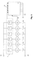
- Fig. 1 shows a schematic view of an embodiment of the present invention.
- the reference numerals 10 and 20 denote connections to an external load supply network, usually the network provided by an RU. Even though only two connections are shown in Fig. 1 noted that the drawing is only to be understood schematically and includes any form of load connection, be it single-phase or three-phase (three-phase).
- Load consumption devices 2.1, 2.2, ... 2.6 The term "load consumption device” is in connection with the present description in general to understand, i.e. it includes every facility, one can consume electrical load.
- the Load consumption devices 2.1 - 2.6 electrical systems be like a pumping station, a car wash, an oven, a hot water boiler, etc.
- load consuming devices e.g. separate Connections in one household, or even whole Households.
- the reference number 1 denotes a device for Providing information regarding the Operating condition of the load consuming devices 2.1 - 2.6.
- the device 1 generally gives this information to a Control device 4, as shown schematically by arrows 51 specified.
- the control device 4 generates depending on the overall state defined by the information, but without direct measurement of the total load actually used, Load control signals to influence the operating status at least part of the load consumption devices 2.1 - 2.6, which is indicated by the output arrow 53 in Fig. 1.
- the load control signals 53 can be in any suitable form are issued, i.e. directly to the load consumers 2.1 - 2.6, to specially established for this purpose Circuit breaker, which in Fig. 1 as switch 3.1 - 3.6 are indicated, or to any other specific task reasonable kind. It is also possible that the Load control signals partly to specially provided breakers go, sometimes directly to the load consumers. A signal delivery directly to the load consumer is possible if this Load consumers have appropriate signal inputs, to receive and process the load control signal. Conversely, for those load consumers that do not corresponding signal inputs or none for processing Such signals have suitable control electronics is one Approval or prevention of the company via a Circuit breaker that is in the electrical Circuit of the associated load consumption device switched is possible.
- Circuit breaking means e.g. of controllable Protect lies in the simple assembly, since the appropriate break switch near the Load connections 10, 20 or the main fuses (not shown) the load consumers can be arranged, together with the control system 4. This makes assembly easier and avoids a high wiring effort.
- the device 1 for providing information can basically be designed in any way as long as the relevant information is provided become.
- corresponding signal outputs the load consumer 2.1 - 2.6, which Output operating state information that form device 1 or form part of the device 1.
- Another Possibility to provide information regarding the Operating state consists of separate sensors or Provide signaling devices 1.1 - 1.6, which switch on / off of assigned load consumers 2.1 - 2.6.
- sensors or signal transmitters are Load shedding relay, i.e. Switch arrangements in which a Current flow for closing a secondary switch leads from which a simple signal is obtained that the Control 4 can be supplied.
- the sensors are simply inserted into the circuit of the corresponding load consumer switched, as by the Elements 1.1 - 1.6 in relation to consumers 2.1 - 2.6 indicated in Fig. 1, so that the beginning of a Current flow to the corresponding consumer from the controller 4 can be determined.
- the overall condition defined by the sensor signals is then generated Control 4 output signals, e.g. to one or more Circuit breakers 3.1 - 3.6. If one of the Sensors 1.1 - 1.6 register the start of a current flow, and communicates this as a signal to the controller 4, the Control should be designed so that it is in front of a significant increase in current already an output signal can generate, e.g. to interrupt the current flow when the overall condition is such that a current flow to the new one Consumers mean that the threshold load has been exceeded would.
- a commercially available programmable logic controller (SPS) meets these requirements.
- Fig. 1 is also indicated that in addition to the Device 1 for providing information regarding the operating state, the load consumers additional Can provide information to the controller 4 as by arrow 52 from device 2.6 to controller 4 hinted at as an example. Examples of such Additional information could be additional operating data, such as. the water temperature of a boiler, etc.
- Fig. 1 Although it is not shown in Fig. 1, others can Signal generators can be provided, which the controller 4 Provide input signals. Examples of this are a Twilight switch (to give the controller information about the To provide lighting conditions), or similar Measuring equipment. A signal input on the Control 4 may be provided, the information regarding the EVU network receives, e.g. regarding the switchover time-dependent tariffs or similar
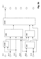
- the controller 4 is preferably a programmable logic controller, the signal inputs of which Signals of the device 1 to provide Receive information regarding the operating status, and whose outputs load control signals to corresponding Spend facilities, e.g. to those indicated in Fig. 1 Circuit breaker 3.1 - 3.6 or directly to the load consumers.
- the one indicated in FIG. 1 An example would be any sensor 1.1 - 1.6 with one respective input of the controller 4 connected, and each Interrupt switch 3.1 - 3.6 with a respective output the control 4.
- FIG. 2 shows the PLC 4, as well as input elements 1 and controlled operating state influencing means 3 (the load consumers are in Fig. 2 not illustrated). 2 also shows an example with Phase power supply.
- the programming of the controller 4 is according to the Conditions and objectives of the area determined in which the present invention is used. With in other words, programming is always individual for the respective plants and related objectives determine.
- An example is a business mentioned in the form of a gas station at which the Load consumers 2.1 - 2.6 are electrical systems, e.g. a pump, a lifting platform, a lighting system, etc.
- the Operating status signals of the individual consumers which preferably simple on / off signals from the respective Load shedding relays assigned to systems provide one Overall status.
- To program which Dependencies between certain input signals (or the Lack of certain input signals) and certain There are load control signals at the output, first one Analysis of the systems to be controlled. In other Words, it is determined what consumption with each system goes hand in hand to then determine which facilities are common can be operated without exceeding the Threshold load takes place.
- the output of the controller 4, which to the load consumer 2.6 belonging breaker 3.6, could e.g. on logically with the inputs of the controller 4 be linked (to which on / off signals for the respective Consumers are concerned) that an overall condition that one Switch-on state of consumers 2.4 and 2.5 indicates one Locking device 2.6 would cause e.g. a Opening switch 3.6, or a corresponding inhibition signal directly to the device 2.6, if this for reception and for Processing such a signal is formed.
- On the other hand could be the logical link between the inputs and Outputs for the output that leads to switch 3.6, see above be that an overall state in which only the device 2.2 and the device 2.4 are switched on, an operation of the Device 2.6 would not conflict.
- the programming of the controller 4 can also be in the form of AND gates or OR gates in any arrangement and Link are expressed, the input signals of the Control represent the input signals of the gates, and the Output signals of the gates the output signals of the control, which also represent load control signals.
- 3a shows an example, in which a load control signal for the load consumer 2.4 is generated (output A4.4). As you can see, the entrances are logically linked so that a threshold load is exceeded is not possible by the device 2.4.
- 3b shows a corresponding example for the control of the device 2.1 (exit A4.1).
- controller 4 can be designed that in the presence of a certain overall condition (expressed by the operating status signals) the desire to switch on another load consumer to one delayed activation leads, be it under temporary switching off of other load consumers, or under complete retention of the previous overall condition.
Landscapes
- Engineering & Computer Science (AREA)
- Power Engineering (AREA)
- Supply And Distribution Of Alternating Current (AREA)
- Selective Calling Equipment (AREA)
Abstract
Description
- Fig. 1
- ein schematisches Beispiel der vorliegenden Erfindung zeigt,
- Fig. 2
- ein schematisches Beispiel der Steuerung zeigt, und
- Fig. 3
- Steuerungsbeispiele zeigt.
Claims (30)
- Vorrichtung zur Verteilung von elektrischer Last auf eine Vielzahl von Lastverbrauchsvorrichtungen, umfassendeine Einrichtung zur Bereitstellung von Informationen betreffend den Betriebszustand jeder Lastverbrauchsvorrichtung, undeine Steuereinrichtung, welche mit der Einrichtung zur Bereitstellung von Informationen verbunden ist, um die Informationen zu empfangen, und welche ausgebildet ist abhängig von dem durch die Informationen definierten Gesamtzustand und ohne direkte Messung der tatsächlichen Last Laststeuersignale zur Beeinflussung des Betriebszustands zumindest eines Teils der Lastverbrauchsvorrichtungen zu erzeugen.
- Vorrichtung nach Anspruch 1, dadurch gekennzeichnet, dass die Einrichtung zur Bereitstellung von Informationen Sensoren umfasst, die das Ein/Ausschalten zumindest eines Teils der Lastverbrauchsvorrichtungen erfassen.
- Vorrichtung nach Anspruch 2, dadurch gekennzeichnet, dass die Sensoren Lastabwurfrelais sind, welche jeweils in den Stromkreis einer zugehörigen Lastverbrauchsvorrichtung geschaltet sind.
- Vorrichtung nach einem der Ansprüche 1 bis 3, dadurch gekennzeichnet, dass die Einrichtung zur Bereitstellung von Informationen Zustandsignal-Ausgabeelemente umfasst, welche in zumindest einem Teil der Lastverbrauchsvorrichtungen angeordnet sind und dafür ausgebildet sind Signale auszugeben, welche den Betriebszustand der betreffenden Lastverbrauchsvorrichtung wiedergeben.
- Vorrichtung nach Anspruch 4, dadurch gekennzeichnet, dass die Zustandsignal-Ausgabeelemente über einen Datenbus mit der Steuereinrichtung verbunden sind.
- Vorrichtung nach einem der Ansprüche 1 bis 5, dadurch gekennzeichnet, dass die Steuereinrichtung eine speicherprogrammierbare Steuerung ist, und die Laststeuersignale mit Hilfe eines gespeicherten Programms erzeugt.
- Vorrichtung nach einem der Ansprüche 1 bis 6, dadurch gekennzeichnet, dass die Steuereinrichtung mit Stromkreisunterbrechungs-Schaltern verbunden ist, welche jeweils in den Stromkreis einer zugehörigen Lastverbrauchvorrichtung geschaltet sind, und welche angeschlossen sind die Laststeuersignale zu empfangen, um ansprechend auf die Laststeuersignale den Stromkreis zu öffnen oder zu schließen.
- Vorrichtung nach Anspruch 7, dadurch gekennzeichnet, dass die Stromkreisunterbrechungs-Schalter steuerbare Schütze sind.
- Vorrichtung nach einem der Ansprüche 1 bis 8, dadurch gekennzeichnet, dass die Steuereinrichtung mit zumindest einem Teil der Lastverbrauchsvorrichtungen verbunden ist, um Laststeuersignale an diese auszugeben.
- Vorrichtung nach Anspruch 9, dadurch gekennzeichnet, dass die Laststeuersignale über einen Datenbus ausgegeben werden.
- Vorrichtung nach einem der Ansprüche 1 bis 10, dadurch gekennzeichnet, dass Beleuchtungskörper einer Beleuchtungsanlage so gruppiert sind, dass sie eine vorbestimmte Zahl von Lastverbrauchsvorrichtungen bilden.
- Vorrichtung nach einem der Ansprüche 1 bis 11, dadurch gekennzeichnet, dass die Steuerung so ausgebildet ist, dass für vorbestimmte Lastverbrauchvorrichtungen eine vom Gesamtzustand abhängige verzögerte Zuschaltung vorgesehen ist.
- Vorrichtung nach einem der Ansprüche 1 bis 12, dadurch gekennzeichnet, dass die Lastverbrauchsvorrichtungen elektrische Anlagen in einem Gewerbebetrieb sind.
- Vorrichtung nach einem der Ansprüche 1 bis 12, dadurch gekennzeichnet, dass die Lastverbrauchsvorrichtungen definierte Stromanschlüsse in einem Haushalt sind.
- Vorrichtung nach einem der Ansprüche 1 bis 12, dadurch gekennzeichnet, dass die Lastverbrauchsvorrichtungen Einzelhaushalte in einem an eine Verteilerstation angeschlossenen Wohngebiet sind.
- Verfahren zur Verteilung von elektrischer Last auf eine Vielzahl von Lastverbrauchsvorrichtungen, umfassendBereitstellung von Informationen betreffend den Betriebszustand jeder Lastverbrauchsvorrichtung, undErzeugung von Laststeuersignalen zur Beeinflussung des Betriebszustands zumindest eines Teils der Lastverbrauchsvorrichtungen, abhängig von dem durch die Informationen definierten Gesamtzustand und ohne direkte Messung der tatsächlichen Last.
- Verfahren nach Anspruch 16, dadurch gekennzeichnet, dass die Informationen durch Sensoren bereitgestellt wird, die das Ein/Ausschalten zumindest eines Teils der Lastverbrauchsvorrichtungen erfassen.
- Verfahren nach Anspruch 16, dadurch gekennzeichnet, dass die Sensoren Lastabwurfrelais sind, welche jeweils in den Stromkreis einer zugehörigen Lastverbrauchsvorrichtung geschaltet sind.
- Verfahren nach einem der Ansprüche 16 bis 18, dadurch gekennzeichnet, dass die Informationen durch Zustandsignal-Ausgabeelemente bereitgestellt werden, welche in zumindest einem Teil der Lastverbrauchsvorrichtungen angeordnet sind und dafür ausgebildet sind Signale auszugeben, welche den Betriebszustand der betreffenden Lastverbrauchsvorrichtung wiedergeben.
- Verfahren nach Anspruch 19, dadurch gekennzeichnet, dass die Zustandsignal-Ausgabeelemente über einen Datenbus mit der Steuereinrichtung verbunden sind.
- Verfahren nach einem der Ansprüche 16 bis 20, dadurch gekennzeichnet, dass die Laststeuersignale mit Hilfe eines gespeicherten Programms in einer speicherprogrammierbaren Steuerung erzeugt werden.
- Verfahren nach einem der Ansprüche 16 bis 21, dadurch gekennzeichnet, dass Stromkreisunterbrechungs-Schalter vorgesehen sind, welche jeweils in den Stromkreis einer zugehörigen Lastverbrauchvorrichtung geschaltet sind, und welche angeschlossen sind die Laststeuersignale zu empfangen, um ansprechend auf die Laststeuersignale den Stromkreis zu öffnen oder zu schließen.
- Verfahren nach Anspruch 22, dadurch gekennzeichnet, dass die Stromkreisunterbrechungs-Schalter steuerbare Schütze sind.
- Verfahren nach einem der Ansprüche 16 bis 23, dadurch gekennzeichnet, dass die Laststeuersignale an zumindest einen Teil der Steuereinrichtung Lastverbrauchsvorrichtungen ausgegeben werden.
- Verfahren nach Anspruch 24, dadurch gekennzeichnet, dass die Laststeuersignale über einen Datenbus ausgegeben werden.
- Verfahren nach einem der Ansprüche 16 bis 25, dadurch gekennzeichnet, dass Beleuchtungskörper einer Beleuchtungsanlage so gruppiert sind, dass sie eine vorbestimmte Zahl von Lastverbrauchsvorrichtungen bilden.
- Verfahren nach einem der Ansprüche 16 bis 26, dadurch gekennzeichnet, dass die Steuerung so ausgebildet ist, dass für vorbestimmte Lastverbrauchvorrichtungen eine vom Gesamtzustand abhängige verzögerte Zuschaltung vorgesehen ist.
- Verfahren nach einem der Ansprüche 16 bis 27, dadurch gekennzeichnet, dass die Lastverbrauchsvorrichtungen elektrische Anlagen in einem Gewerbebetrieb sind.
- Verfahren nach einem der Ansprüche 16 bis 27, dadurch gekennzeichnet, dass die Lastverbrauchsvorrichtungen definierte Stromanschlüsse in einem Haushalt sind.
- Verfahren nach einem der Ansprüche 16 bis 27, dadurch gekennzeichnet, dass die Lastverbrauchsvorrichtungen Einzelhaushalte in einem an eine Verteilerstation angeschlossenen Wohngebiet sind.
Applications Claiming Priority (2)
| Application Number | Priority Date | Filing Date | Title |
|---|---|---|---|
| DE10036866A DE10036866A1 (de) | 2000-07-28 | 2000-07-28 | Vorrichtung und Verfahren zur Verteilung von elektrischer Last auf eine Vielzahl von Lastverbrauchsvorrichtungen |
| DE10036866 | 2000-07-28 |
Publications (2)
| Publication Number | Publication Date |
|---|---|
| EP1176690A2 true EP1176690A2 (de) | 2002-01-30 |
| EP1176690A3 EP1176690A3 (de) | 2005-02-16 |
Family
ID=7650570
Family Applications (1)
| Application Number | Title | Priority Date | Filing Date |
|---|---|---|---|
| EP01118290A Withdrawn EP1176690A3 (de) | 2000-07-28 | 2001-07-30 | Vorrichtung und Verfahren zur Verteilung von elektrischer Last auf eine Vielzahl von Lastverbrauchsvorrichtungen |
Country Status (2)
| Country | Link |
|---|---|
| EP (1) | EP1176690A3 (de) |
| DE (1) | DE10036866A1 (de) |
Cited By (1)
| Publication number | Priority date | Publication date | Assignee | Title |
|---|---|---|---|---|
| WO2013088229A3 (en) * | 2011-12-15 | 2014-07-31 | Restore Nv | Automated demand response energy management system |
Family Cites Families (4)
| Publication number | Priority date | Publication date | Assignee | Title |
|---|---|---|---|---|
| DE3045023A1 (de) * | 1980-11-28 | 1982-07-01 | Gerda 8000 München Schmidt | Steuerung von mehreren in einer technischen anlage zusammengefassten elektrischen apparaten |
| CN1076529C (zh) * | 1996-04-01 | 2001-12-19 | 南方电力有限公司 | 配电频率继电器 |
| DE19621333A1 (de) * | 1996-05-28 | 1997-12-04 | Aeg Hausgeraete Gmbh | Verfahren und Vorrichtung zum Steuern von Wechselstromverbrauchern |
| DE19842043B4 (de) * | 1998-09-14 | 2005-11-17 | Gerda Schmidt | Verfahren zur automatischen und verbraucherorientierten Minimierung des Gesamtstromverbrauchs und der Leistungsspitze einer Gruppe von an einem Leistungsversorgungsnetz angeschlossenen einzelnen elektrischen Verbrauchern |
-
2000
- 2000-07-28 DE DE10036866A patent/DE10036866A1/de not_active Withdrawn
-
2001
- 2001-07-30 EP EP01118290A patent/EP1176690A3/de not_active Withdrawn
Cited By (6)
| Publication number | Priority date | Publication date | Assignee | Title |
|---|---|---|---|---|
| WO2013088229A3 (en) * | 2011-12-15 | 2014-07-31 | Restore Nv | Automated demand response energy management system |
| US8825219B2 (en) | 2011-12-15 | 2014-09-02 | Restore Nv | Automated demand response energy management system |
| US8838281B2 (en) | 2011-12-15 | 2014-09-16 | Restore Nv | Automated demand response energy management system |
| JP2015506031A (ja) * | 2011-12-15 | 2015-02-26 | レストレ・エンフェーRestore Nv | 自動需要応答エネルギ管理システム |
| JP2016167300A (ja) * | 2011-12-15 | 2016-09-15 | レストレ・エンフェーRestore Nv | 自動需要応答エネルギ管理システム |
| US9581979B2 (en) | 2011-12-15 | 2017-02-28 | Restore Nv | Automated demand response energy management system |
Also Published As
| Publication number | Publication date |
|---|---|
| DE10036866A1 (de) | 2002-02-28 |
| EP1176690A3 (de) | 2005-02-16 |
Similar Documents
| Publication | Publication Date | Title |
|---|---|---|
| EP2697888B1 (de) | Verfahren zur bestimmung der topologie eines niederspannungsnetzes | |
| EP0648005B1 (de) | Vorrichtung zur Begrenzung der Leistungsaufnahme eines aus einem Energieversorgungsanschluss gespeisten Haushaltes | |
| EP3336995B1 (de) | Verfahren, steuereinrichtung und system zum ermitteln von zustandswerten zur beschreibung von betriebszuständen in einem teilnetz eines energieversorgungsnetzes | |
| EP2548276B1 (de) | Verfahren und vorrichtung zur elektrischen verbrauchs- und erzeugungserfassung | |
| DE19615959C1 (de) | Verfahren und System zur Optimierung und zum Management des Verbrauches an elektrischer Energie in Industriebetrieben | |
| DE112018006592T5 (de) | Stromversorgungsvermittlungsvorrichtung, Stromversorgungsvorrichtung, Stromverbrauchsvorrichtung, Stromversorgungsfernsteuervorrichtung, Stromversorgungsvermittlungsverfahren und Stromsystem | |
| DE102007063513B4 (de) | Produktionsenergiedatenerfassungs- und -analysesystem | |
| DE19842043A1 (de) | Verfahren und Vorrichtung zur automatischen und verbraucherorientierten Leistungsminimierung elektrischer Verbraucher | |
| DE4019523C2 (de) | ||
| DE102016218352A1 (de) | Bewerten einer elektrischen Belastbarkeit eines elektrischen Energieverteilungsnetzes | |
| DE69512138T2 (de) | Verwaltungsvorrichtung für elektrische Energieverteilungsanlage | |
| EP1072081B1 (de) | Verfahren zum regeln der gesamtleistung von energietechnischen anlagen, insbesondere einer gruppe von elektrischen verbrauchern | |
| EP1176690A2 (de) | Vorrichtung und Verfahren zur Verteilung von elektrischer Last auf eine Vielzahl von Lastverbrauchsvorrichtungen | |
| CH714695A1 (de) | Vorrichtung, System und Verfahren zum Steuern elektrischer Lasten. | |
| DE2316341A1 (de) | Verfahren zum stufenlosen verteilen elektrischer energie | |
| EP1217300A1 (de) | Verfahren und Vorrichtung zum Betrieb einer mehrere Komponenten umfassenden technischen Anlage, insbesondere einer Verbrennungsanlage zum Erzeugen von elektrischer Energie | |
| DE102012216369A1 (de) | Elektrische einrichtung zum anschluss an ein infrastrukturstromnetz und verfahren | |
| DE102007016635A1 (de) | Vorrichtung und Verfahren zum Verteilen elektrischer Energie | |
| EP2400360A1 (de) | Automatisierungsgerät und Verfahren zur Energieoptimierung | |
| EP3268755B1 (de) | System zur ermittlung des energieverbrauchs eines einzelnen verbrauchers | |
| DE102021101589A1 (de) | Steuersystem zur optimierten Elektroenergienutzung | |
| EP2993548B1 (de) | Regelung einer spannungseinspeisung | |
| EP4053461B1 (de) | Verfahren zum betreiben einer heizungsanlage | |
| DE202008017778U1 (de) | Einrichtung zur Maximallasteinstellung | |
| DE102009052452A1 (de) | Verfahren und Vorrichtung zur Optimierung des Energieverbrauchs einer Einrichtung mit einer Vielzahl elektrischer Verbraucher |
Legal Events
| Date | Code | Title | Description |
|---|---|---|---|
| PUAI | Public reference made under article 153(3) epc to a published international application that has entered the european phase |
Free format text: ORIGINAL CODE: 0009012 |
|
| AK | Designated contracting states |
Kind code of ref document: A2 Designated state(s): AT BE CH CY DE DK ES FI FR GB GR IE IT LI LU MC NL PT SE TR |
|
| AX | Request for extension of the european patent |
Free format text: AL;LT;LV;MK;RO;SI |
|
| PUAL | Search report despatched |
Free format text: ORIGINAL CODE: 0009013 |
|
| AK | Designated contracting states |
Kind code of ref document: A3 Designated state(s): AT BE CH CY DE DK ES FI FR GB GR IE IT LI LU MC NL PT SE TR |
|
| AX | Request for extension of the european patent |
Extension state: AL LT LV MK RO SI |
|
| STAA | Information on the status of an ep patent application or granted ep patent |
Free format text: STATUS: THE APPLICATION IS DEEMED TO BE WITHDRAWN |
|
| 18D | Application deemed to be withdrawn |
Effective date: 20050202 |