EP1176748A2 - Méthode et appareil pour la correction d'erreurs - Google Patents
Méthode et appareil pour la correction d'erreurs Download PDFInfo
- Publication number
- EP1176748A2 EP1176748A2 EP01117502A EP01117502A EP1176748A2 EP 1176748 A2 EP1176748 A2 EP 1176748A2 EP 01117502 A EP01117502 A EP 01117502A EP 01117502 A EP01117502 A EP 01117502A EP 1176748 A2 EP1176748 A2 EP 1176748A2
- Authority
- EP
- European Patent Office
- Prior art keywords
- error correction
- data
- code
- decoding
- coded sequence
- Prior art date
- Legal status (The legal status is an assumption and is not a legal conclusion. Google has not performed a legal analysis and makes no representation as to the accuracy of the status listed.)
- Withdrawn
Links
Images









Classifications
-
- H—ELECTRICITY
- H04—ELECTRIC COMMUNICATION TECHNIQUE
- H04L—TRANSMISSION OF DIGITAL INFORMATION, e.g. TELEGRAPHIC COMMUNICATION
- H04L1/00—Arrangements for detecting or preventing errors in the information received
- H04L1/004—Arrangements for detecting or preventing errors in the information received by using forward error control
- H04L1/0056—Systems characterized by the type of code used
- H04L1/0059—Convolutional codes
-
- H—ELECTRICITY
- H03—ELECTRONIC CIRCUITRY
- H03M—CODING; DECODING; CODE CONVERSION IN GENERAL
- H03M13/00—Coding, decoding or code conversion, for error detection or error correction; Coding theory basic assumptions; Coding bounds; Error probability evaluation methods; Channel models; Simulation or testing of codes
- H03M13/29—Coding, decoding or code conversion, for error detection or error correction; Coding theory basic assumptions; Coding bounds; Error probability evaluation methods; Channel models; Simulation or testing of codes combining two or more codes or code structures, e.g. product codes, generalised product codes, concatenated codes, inner and outer codes
- H03M13/2933—Coding, decoding or code conversion, for error detection or error correction; Coding theory basic assumptions; Coding bounds; Error probability evaluation methods; Channel models; Simulation or testing of codes combining two or more codes or code structures, e.g. product codes, generalised product codes, concatenated codes, inner and outer codes using a block and a convolutional code
-
- H—ELECTRICITY
- H03—ELECTRONIC CIRCUITRY
- H03M—CODING; DECODING; CODE CONVERSION IN GENERAL
- H03M13/00—Coding, decoding or code conversion, for error detection or error correction; Coding theory basic assumptions; Coding bounds; Error probability evaluation methods; Channel models; Simulation or testing of codes
- H03M13/35—Unequal or adaptive error protection, e.g. by providing a different level of protection according to significance of source information or by adapting the coding according to the change of transmission channel characteristics
- H03M13/356—Unequal error protection [UEP]
-
- H—ELECTRICITY
- H03—ELECTRONIC CIRCUITRY
- H03M—CODING; DECODING; CODE CONVERSION IN GENERAL
- H03M13/00—Coding, decoding or code conversion, for error detection or error correction; Coding theory basic assumptions; Coding bounds; Error probability evaluation methods; Channel models; Simulation or testing of codes
- H03M13/37—Decoding methods or techniques, not specific to the particular type of coding provided for in groups H03M13/03 - H03M13/35
- H03M13/3707—Adaptive decoding and hybrid decoding, e.g. decoding methods or techniques providing more than one decoding algorithm for one code
- H03M13/3715—Adaptation to the number of estimated errors or to the channel state
-
- H—ELECTRICITY
- H03—ELECTRONIC CIRCUITRY
- H03M—CODING; DECODING; CODE CONVERSION IN GENERAL
- H03M13/00—Coding, decoding or code conversion, for error detection or error correction; Coding theory basic assumptions; Coding bounds; Error probability evaluation methods; Channel models; Simulation or testing of codes
- H03M13/63—Joint error correction and other techniques
- H03M13/635—Error control coding in combination with rate matching
- H03M13/6362—Error control coding in combination with rate matching by puncturing
-
- H—ELECTRICITY
- H03—ELECTRONIC CIRCUITRY
- H03M—CODING; DECODING; CODE CONVERSION IN GENERAL
- H03M13/00—Coding, decoding or code conversion, for error detection or error correction; Coding theory basic assumptions; Coding bounds; Error probability evaluation methods; Channel models; Simulation or testing of codes
- H03M13/65—Purpose and implementation aspects
- H03M13/6508—Flexibility, adaptability, parametrability and configurability of the implementation
- H03M13/6516—Support of multiple code parameters, e.g. generalized Reed-Solomon decoder for a variety of generator polynomials or Galois fields
-
- H—ELECTRICITY
- H04—ELECTRIC COMMUNICATION TECHNIQUE
- H04L—TRANSMISSION OF DIGITAL INFORMATION, e.g. TELEGRAPHIC COMMUNICATION
- H04L1/00—Arrangements for detecting or preventing errors in the information received
- H04L1/0001—Systems modifying transmission characteristics according to link quality, e.g. power backoff
- H04L1/0023—Systems modifying transmission characteristics according to link quality, e.g. power backoff characterised by the signalling
- H04L1/0025—Transmission of mode-switching indication
-
- H—ELECTRICITY
- H04—ELECTRIC COMMUNICATION TECHNIQUE
- H04L—TRANSMISSION OF DIGITAL INFORMATION, e.g. TELEGRAPHIC COMMUNICATION
- H04L1/00—Arrangements for detecting or preventing errors in the information received
- H04L1/004—Arrangements for detecting or preventing errors in the information received by using forward error control
- H04L1/0041—Arrangements at the transmitter end
-
- H—ELECTRICITY
- H04—ELECTRIC COMMUNICATION TECHNIQUE
- H04L—TRANSMISSION OF DIGITAL INFORMATION, e.g. TELEGRAPHIC COMMUNICATION
- H04L1/00—Arrangements for detecting or preventing errors in the information received
- H04L1/004—Arrangements for detecting or preventing errors in the information received by using forward error control
- H04L1/0045—Arrangements at the receiver end
- H04L1/0047—Decoding adapted to other signal detection operation
- H04L1/005—Iterative decoding, including iteration between signal detection and decoding operation
-
- H—ELECTRICITY
- H04—ELECTRIC COMMUNICATION TECHNIQUE
- H04L—TRANSMISSION OF DIGITAL INFORMATION, e.g. TELEGRAPHIC COMMUNICATION
- H04L1/00—Arrangements for detecting or preventing errors in the information received
- H04L1/004—Arrangements for detecting or preventing errors in the information received by using forward error control
- H04L1/0056—Systems characterized by the type of code used
- H04L1/0061—Error detection codes
-
- H—ELECTRICITY
- H04—ELECTRIC COMMUNICATION TECHNIQUE
- H04L—TRANSMISSION OF DIGITAL INFORMATION, e.g. TELEGRAPHIC COMMUNICATION
- H04L1/00—Arrangements for detecting or preventing errors in the information received
- H04L1/004—Arrangements for detecting or preventing errors in the information received by using forward error control
- H04L1/0056—Systems characterized by the type of code used
- H04L1/0064—Concatenated codes
- H04L1/0065—Serial concatenated codes
-
- H—ELECTRICITY
- H04—ELECTRIC COMMUNICATION TECHNIQUE
- H04L—TRANSMISSION OF DIGITAL INFORMATION, e.g. TELEGRAPHIC COMMUNICATION
- H04L1/00—Arrangements for detecting or preventing errors in the information received
- H04L1/004—Arrangements for detecting or preventing errors in the information received by using forward error control
- H04L1/0056—Systems characterized by the type of code used
- H04L1/0064—Concatenated codes
- H04L1/0066—Parallel concatenated codes
-
- H—ELECTRICITY
- H03—ELECTRONIC CIRCUITRY
- H03M—CODING; DECODING; CODE CONVERSION IN GENERAL
- H03M13/00—Coding, decoding or code conversion, for error detection or error correction; Coding theory basic assumptions; Coding bounds; Error probability evaluation methods; Channel models; Simulation or testing of codes
- H03M13/03—Error detection or forward error correction by redundancy in data representation, i.e. code words containing more digits than the source words
- H03M13/05—Error detection or forward error correction by redundancy in data representation, i.e. code words containing more digits than the source words using block codes, i.e. a predetermined number of check bits joined to a predetermined number of information bits
- H03M13/09—Error detection only, e.g. using cyclic redundancy check [CRC] codes or single parity bit
-
- H—ELECTRICITY
- H03—ELECTRONIC CIRCUITRY
- H03M—CODING; DECODING; CODE CONVERSION IN GENERAL
- H03M13/00—Coding, decoding or code conversion, for error detection or error correction; Coding theory basic assumptions; Coding bounds; Error probability evaluation methods; Channel models; Simulation or testing of codes
- H03M13/03—Error detection or forward error correction by redundancy in data representation, i.e. code words containing more digits than the source words
- H03M13/05—Error detection or forward error correction by redundancy in data representation, i.e. code words containing more digits than the source words using block codes, i.e. a predetermined number of check bits joined to a predetermined number of information bits
- H03M13/13—Linear codes
- H03M13/15—Cyclic codes, i.e. cyclic shifts of codewords produce other codewords, e.g. codes defined by a generator polynomial, Bose-Chaudhuri-Hocquenghem [BCH] codes
-
- H—ELECTRICITY
- H03—ELECTRONIC CIRCUITRY
- H03M—CODING; DECODING; CODE CONVERSION IN GENERAL
- H03M13/00—Coding, decoding or code conversion, for error detection or error correction; Coding theory basic assumptions; Coding bounds; Error probability evaluation methods; Channel models; Simulation or testing of codes
- H03M13/03—Error detection or forward error correction by redundancy in data representation, i.e. code words containing more digits than the source words
- H03M13/05—Error detection or forward error correction by redundancy in data representation, i.e. code words containing more digits than the source words using block codes, i.e. a predetermined number of check bits joined to a predetermined number of information bits
- H03M13/13—Linear codes
- H03M13/15—Cyclic codes, i.e. cyclic shifts of codewords produce other codewords, e.g. codes defined by a generator polynomial, Bose-Chaudhuri-Hocquenghem [BCH] codes
- H03M13/151—Cyclic codes, i.e. cyclic shifts of codewords produce other codewords, e.g. codes defined by a generator polynomial, Bose-Chaudhuri-Hocquenghem [BCH] codes using error location or error correction polynomials
- H03M13/152—Bose-Chaudhuri-Hocquenghem [BCH] codes
-
- H—ELECTRICITY
- H03—ELECTRONIC CIRCUITRY
- H03M—CODING; DECODING; CODE CONVERSION IN GENERAL
- H03M13/00—Coding, decoding or code conversion, for error detection or error correction; Coding theory basic assumptions; Coding bounds; Error probability evaluation methods; Channel models; Simulation or testing of codes
- H03M13/37—Decoding methods or techniques, not specific to the particular type of coding provided for in groups H03M13/03 - H03M13/35
- H03M13/39—Sequence estimation, i.e. using statistical methods for the reconstruction of the original codes
- H03M13/41—Sequence estimation, i.e. using statistical methods for the reconstruction of the original codes using the Viterbi algorithm or Viterbi processors
-
- H—ELECTRICITY
- H04—ELECTRIC COMMUNICATION TECHNIQUE
- H04L—TRANSMISSION OF DIGITAL INFORMATION, e.g. TELEGRAPHIC COMMUNICATION
- H04L1/00—Arrangements for detecting or preventing errors in the information received
- H04L1/004—Arrangements for detecting or preventing errors in the information received by using forward error control
- H04L1/0045—Arrangements at the receiver end
- H04L1/0047—Decoding adapted to other signal detection operation
- H04L1/005—Iterative decoding, including iteration between signal detection and decoding operation
- H04L1/0051—Stopping criteria
-
- H—ELECTRICITY
- H04—ELECTRIC COMMUNICATION TECHNIQUE
- H04L—TRANSMISSION OF DIGITAL INFORMATION, e.g. TELEGRAPHIC COMMUNICATION
- H04L1/00—Arrangements for detecting or preventing errors in the information received
- H04L1/004—Arrangements for detecting or preventing errors in the information received by using forward error control
- H04L1/0045—Arrangements at the receiver end
- H04L1/0052—Realisations of complexity reduction techniques, e.g. pipelining or use of look-up tables
Definitions
- the present invention relates to an error correction system in a digital radio device, especially a system for efficiently transmitting data during low bit rate transmission. More particularly, the invention relates to a method and an apparatus for error correction with a concatenated code constitution.
- Fig. 19 is a block diagram showing an apparatus used for the error correction method of channel coding in a public utility digital mobile communication system (RCR STD-39B).
- a reference numeral 34 denotes an error detection code (CRC) coding circuit for information; 35 a fixed-bit insertion circuit; 36 a convolutional coding circuit; and 37 an interleave generation circuit.
- Fig. 20 shows a change in the bit length at each of the circuits, wherein a reference numeral 38 denotes a change in the bit length at the output time of an error CRC coding; 39 at the output time of a fixed bit inserting circuit; 40 at the output time of a convolutional coding circuit; and 41 at the output time of interleave generation.
- a 16-bit error detection code (CRC) is added to data (38 in Fig. 20).
- CRC error detection code
- the fixed bit insertion circuit 35 a 5-bit "0" fixed data as a tail bit of a convolutional code is added to the data generated by the error detection code coding circuit 34, and the CRC check bit. After the check bit, (39 in Fig. 29).
- convolutional coding circuit 36 convolutional coding of a rate 1/2 is carried out at a constraint length 6 (40 in Fig. 20).
- a convolutional coded sequence is dispersed timewise (41 in Fig. 2) to increase resistance to a burst error.
- Fig. 21 is a block diagram showing an apparatus used for the concatenated code of a digital video broadcasting (DBV) error correction system.
- a reference numeral 42 denotes an external code generation circuit; 43 an interleave generation circuit; and 44 an internal code generation circuit.
- RS Read-Solomon
- the coded RS coded sequence enters the interleave generation circuit 43, and 12-stage convolutional interleaving is carried out.
- the coded sequence having been subjected to interleaving is changed from a maximum rate of 1/2 to a rate of 7/8 depending on a channel state, based on the convolutional encoder of a rate of 1/2 with a constraint length 7.
- Fig. 22 is a schematic diagram showing a decoder for an error correction code, which is described in Japanese Patent Application Laid-Open No. 1995-202719.
- a reference numeral 45 denotes a flag addition mode determination circuit for determining at or over what number of errors a flag is to be added based on the number of errors obtained from an internal code; 46 a flag addition circuit for adding a flag upon receiving the determination result of the flag addition; and 47 an external code decoding circuit.
- the flag addition mode determination circuit 45 calculates the number of code words having i number of errors, which is obtained by decoding an internal code composed of a plurality of code words, and then performs a plurality of flag control operations based on the detected i number errors.
- flag addition is carried out, which provides a plurality of bits of reliability information.
- the external code decoding circuit 47 selects, based on the plurality of flags, one of a plurality of decoding modes, and executes decoding.
- the present invention was made to solve the foregoing problems, and objects of the invention are to provide a method and an apparatus for error correction, designed to build a digital radio communication system capable of transmitting data at a high speed when the number of error is small on a transmission path, and transmitting data with high reliability when the number of error is large on the transmission path.
- Other objects of the invention are to provide a method and an apparatus for error correction, designed to perform decoding without any control of a reliability information addition mode, when the external code of a concatenated code is subjected to decoding by using the number of corrected errors for an internal code.
- a method and an apparatus for error correction of the present invention comprise transmission means and a method thereof, wherein the transmission means comprises: coding means for protecting data to be transmitted by a plurality of error correction codes; outputting means for first transmitting an error correction coded sequence including data, coded by an error correction code having small redundancy, including data, and subsequently transmitting an error correction coded sequence coded by an error correction code having a large correction capability; and storing section for storing the subsequently transmitted error correction coded sequence coded by an error correction code having a large correction capability.
- a method and an apparatus for error correction of the present invention further comprise receiving means and a method thereof, wherein the receiving means comprises: a plurality of decoding means for decoding an error correction coded sequence including previously transmitted data and a subsequently transmitted error correction coded sequence including data coded by an error correction code having a large correction capability at a receiving side; determining means for decoding the error correction coded sequence including the previously transmitted data, and making determination as to the presence of an error in a result of the decoding; and outputting means for immediately outputting a result thereof if the presence of no errors is determined by the determining means.
- a method and an apparatus for error correction of the present invention comprise transmission means and a method thereof, wherein the transmission means comprises coding means for protecting data to be transmitted by an error correction code having a large correction capability; coding means of an error correction code having small redundancy for protecting the data with respect to the check of the error correction code having the large correction capability; input switching means for entering the data and an error correction coded sequence coded by an error correction code having a large correction capability to the coding means of the error correction code having small redundancy; and storing section for storing an error correction coded sequence coded by an error correction code having a large correction capability for subsequent transmission.
- a method and an apparatus for error correction of the present invention comprise receiving means and a method thereof, wherein it comprises: first means for decoding an error correction code having small redundancy at a receiving side; storing section for the decoded data by the decoding means regarding data; determining means for making determination as to the presence of an error in the decoding data of the decoding means; second decoding means for outputting data from the decoded data stored in the storing section and an error correction coded sequence coded by an error correction code having a large correction capability outputted from the first decoding means; and outputting means for immediately outputting a result thereof if the presence of no errors is determined by the determining means.
- a method and an apparatus for error correction of the present invention comprise transmission means and a method thereof, wherein the transmission means comprises: coding means for protecting data to be transmitted by one error correction code; transmission procedure means for transmitting first only a part of a coded sequence including data, and subsequently transmitting a remaining error correction coded sequence; and storing section for storing an error correction coded sequence for subsequent transmission.
- a method and an apparatus for error correction of the present invention comprise receiving means and a method thereof, wherein it comprises: decoding means for executing decoding by a part of an error correction coded sequence including previously transmitted data at a receiving side; storing section for storing the sequence to be received; decoding means for synthesizing a subsequently transmitted remaining error correction coded sequence with a part of an error correction coded sequence including the previously transmitted data, stored in the storing section, and then decoding the synthesized sequence; determining means for decoding the error correction coded sequence including the previously transmitted data, and making determination as to the presence of an error in the result of the decoding; and outputting means for immediately outputting the result thereof if the presence of no errors is determined.
- a method and an apparatus for error correction of the present invention comprise transmission means and a method thereof, wherein the transmission means comprises, coding means for an internal code generated by a coded sequence composed of a plurality of code words regarding coding means for concatenated codes; and coding means for an external code for generating a convolutional code.
- a method and an apparatus for error correction of the present invention comprise receiving means and a method thereof, wherein it comprises, regarding decoding means for concatenated codes at a receiving side; first decoding means of an internal code, for decoding a coded sequence composed of a plurality of code words, and outputting the number of errors; and a second decoding means of an external code, for executing decoding by using the decoded data of the internal code, and the number of errors, and based on the rule of a convolutional code.
- Fig. 1 is a block diagram showing a transmission side apparatus used for an error correction method according to the first embodiment of the present invention
- Fig. 3 a block diagram showing a receiving side apparatus.
- a reference numeral 1 denotes a coding circuit of an error correction code A
- 2 a coding circuit of an error correction code B
- 3 an output switching circuit for transmitting the error correction code A or B including data
- 4 a storing section for storing data.
- a reference numeral 5 denotes a decoding circuit of the error correction code A; 6 an error determination circuit for determining whether or not an errors remains in the decoded result of the error correction code A; 7 a storing section for storing decoded data or the coded sequence of the error correction code A; 8 a decoding circuit of the error correction code B; and 9 an output circuit.
- the data stored in the storing section 4 is subjected to coding by the coding circuit 2 of the error correction code B, and transmitted through the output switching circuit 3.
- the error correction code B is a systematic code, in which a check portion is added to the data, then only the check portion may be sent.
- Fig. 2 shows a transmission frame based on the described operation.
- the coded sequence to be received, of the error correction code A including the data transmitted first is subjected to decoding by the decoding circuit 5 of the error correction code A.
- the error determination circuit 6 determines whether or not an error remains in the correction result by the decoding circuit 5 of the error correction code A.
- the method of determination can easily detect errors, if for example an error detection code is contained in the data.
- determination can be made based on the number of corrected errors by a block code, an error correction impossibility flag, or the like.
- the data sequence decoded by the decoding circuit 5 of the error correction code A is stored in the storing section 7.
- the output circuit 9 outputs the result of the decoding by the decoding circuit 5 of the error correction code A as a decoded data sequence, and annuls the data sequence to be received, sent in following the coded sequence of the error correction code A including the data.
- decoding is carried out by the decoding circuit 8 of the error correction code B based on the decoded data sequence stored in the storing section 7 and the data sequence to be received of the subsequently received error correction code B. Then, from the output circuit 9, the result of the decoding by the decoding circuit 8 of the error correction code B is outputted as a decoded data sequence.
- interleaving can be carried out for the error correction codes A and B.
- the data sequence may be divided into a plurality of blocks, and a block having the error correction codes A and B as a pair may be transmitted by a plurality of times.
- the decoded result by the decoding circuit 8 of the error correction code B may be entered to the determination circuit 6 in a manner like that indicated by a chain line arrow of Fig. 3. If the presence of an error is determined, then the decoding result by the decoding circuit 8 of the error correction code B may be entered to the decoding circuit 5 of the error correction code A in a manner like that indicated by a dotted line arrow, and subjected to correction again. At the error determination circuit 6, determination may be made again to see if there are any errors. If no errors are present, then the decoded result may be outputted from the output circuit 9. If the presence of an error is determined, then the decoded result may be stored again in the storing section 7, making it possible to execute repeated decoding, i.e., decoding again by the decoding circuit 8 of the error correction code, as in the foregoing case.
- the two kinds of error correction codes i.e., the error correction codes A and B, were prepared.
- three or more kinds of error correction codes can be used.
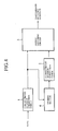
- Fig. 4 is a block diagram showing a transmission side apparatus of such a configuration.
- the storing section 4 is provided in a stage after that of the coding circuit 1, and adapted to store the coded sequence of the error correction code A.
- Other components are similar to those of the embodiment 1, denoted by similar reference numerals, and description thereof will be omitted.
- data is subjected to error correction coding by the coding circuit 1 of the error correction code A.
- a sequence having been subjected to error correction coding by the coding circuit 1 of the error correction code A is stored in the storing section 4.
- the coded sequence including the data, having been subjected to error correction coding by the coding circuit 1 is transmitted through the output switching circuit 3. This operation is continued until the transmission of all the data is completed.
- coding is carried out for the coded sequence stored in the storing section 4 by the coding circuit 2 of the error correction code B, and the result is outputted through the output switching circuit 3.
- the error correction code B is a systematic code, in which a check portion is added to the date, then only a check portion may be transmitted.
- the configuration of the receiving side is similar to that of Fig. 3.
- the coded sequence of the error correction code A including data decoded by the decoding circuit 5 of the error correction code A is stored. If the presence of no errors is determined by the determination circuit 6, as in the case of the embodiment 1, the data is outputted from the output circuit 9, the sequence of the subsequent error correction code B is abolished. If an error is detected, then the coded sequence of the error correction code A including the data is subjected to decoding by the decoding circuit 8 of the error correction code B.
- the data can be outputted from the output circuit 9.
- the result of decoding by the decoding circuit 8 of the error correction code B is entered to the determination circuit 6 in a manner like that indicated by the chain line arrow of Fig. 3, determination is made as to whether or not an error remains. If there is an error, the decoded result is entered again to the decoding circuit 5 of the error correction code A in a manner like that indicated by the dotted line arrow of Fig. 3, and then subjected to decoding.
- interleaving can be carried out in the embodiment 2, and three or more kinds of error correction codes can be used.
- the data sequence may be divided into a plurality of blocks, and a block having the error correction codes A and B as a pair may be transmitted by a plurality of times.
- the error correction code A as a block code such as BCH code or the like
- the error correction code B as a convolutional code of a systematic type
- the number of corrected errors is monitored in the decoding circuit 5 of the error correction code A as a block code, and the number of corrected errors is stored with the data in the storing section 7. If it is determined by the determination circuit 6 that an error remains, then the number of corrected errors is entered with the data stored in the storing section 7 at the decoding circuit 8 of the error correction code B, and a check sequence of the error correction code B is entered from the sequence to be received.
- reliability is set to a highest soft determination value for a bit determined to have no errors by the error correction code A.
- a soft determination value corresponding to the number of corrected errors is given.
- a soft determination value equal to that of a check sequence is given, and by Viterbi decoding, for example, soft determination decoding is facilitated, improving the decoding capability.
- the soft determination decoding by the decoding circuit 8 of the error correction code B was carried out only when an error was detected by the determination circuit 6 after the decoding of the coded sequence of the error correction code A as all the block codes containing the data at the decoding circuit 5 of the error correction code A.
- the data stored in the storing section 7 is entered to the decoding circuit 8 of the error correction code B unconditionally.
- Th data may be divided into a plurality, and a block having pluralities of error correction codes A and B are a pair may be transmitted by a plurality of times.
- the transmission form was made on the fixed data length. However, even if a data length is varied, it is possible to perform an operation similar to that of each of the foregoing embodiments by inserting the data length into data.
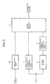
- Fig. 5 is a block diagram showing a transmission side apparatus according to the fourth embodiment applied to the case of a variable data length, in which a data length is inserted into a data.
- a reference numeral 10 denotes a third error correction coding circuit for performing an error correction coding regarding the data length, and its output is entered to the output switching circuit 3. Otherwise, other components are similar to those in Fig. 1.
- the data length is entered to the third coding circuit 10, and error correction coding is carried out.
- the data is outputted before the coded sequence of the error correction code A including data from the output switching circuit 3.
- a maximum vale of the data length is predetermined, and a third error correction code length using the data length as information is constant. Coding by the third error correction coding circuit 10 should preferably be stronger than the error correction code A.
- Fig. 6 shows a transmission frame based on the described operation.
- a reference numeral 11 denotes a third error correction decoding circuit, and its output is entered to each of the decoding circuit 5 of the error correction code A, the error correction determination circuit 6, the storing section 7, the decoding circuit 8, and the output circuit 9.
- Other components are similar to those shown in Fig. 3.
- the third error correction coded sequence including the data length was directly outputted.
- the third error correction coded sequence including the data length may be entered to the coding circuit 1 of the error correction code A, and subjected to coding while it is contained in the error correction code A.
- the coded sequence is decoded by the error correction code A at the decoding circuit 5 of the error correction code A, and then entered to the decoding circuit 11 of the third error correction code to obtain the data length.
- one obtained by coding the data with the third error correction code was transmitted once.
- the data length may not be obtained at the receiving side if an error rate is greatly reduced during the transmission of the data length.
- This problem can be solved by transmitting the third error correction code including the data length by a plurality of times in the coded sequence of the error correction code A.
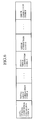
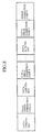
- Fig. 8 is a constitutional view of a transmission frame according the embodiment 5.
- the coded sequence of the error correction code Aincluding all the data is divided into a plurality of blocks, and transmitted in the transmission order of inserting the third coded sequence including the data length for each block.
- the third coded sequence including the data length is stored in the coding circuit 10 of the third error correction code.
- a block length outputted from the coding circuit 1 of the error correction code A is controlled, and the third coded sequence including the data length is inserted therein, and outputted.
- the third error correction code can be provided with an error detection function.
- the data or the error correction code A including the data was subjected to coding by the error correction code B.
- a similar advantage can be obtained by coding the data and the error correction code B by the error correction code A, and transmitting it.
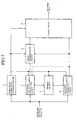
- Fig. 9 is a block diagram showing a transmission side apparatus according to the sixth embodiment.
- a reference numeral 1 denotes the coding circuit of an error correction code A
- 2 the coding circuit of an error correction code B
- 4 a storing section for storing data
- 12 an input circuit for switching an input to the coding circuit 1 of the error correction code A.
- the error correction code B is a systematic code, in which the code is separated into data and a check portion, then it may be only a check portion of the error correction code B that is entered to the input circuit 12 by the coding circuit 2 of the error correction code B.
- a relation between the coding circuit 2 of the error correction code B and the storing section 4 may be opposite.
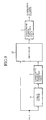
- Fig. 11 is a block diagram showing a receiving side apparatus according to the embodiment 6.
- a reference numeral 5 denotes the decoding circuit of the error correction code A; 6 a determination circuit for determining whether or not an error remains in the decoding result of the error correction code A; 8 the decoding circuit of the error correction code B; and 9 an output circuit.
- the coded sequence to be received, of the error correction code A including first transmitted data is entered to the decoding circuit 5 of the error correction code A, and subjected to decoding.
- the error determination circuit 6 determines whether an error is remaining or not in the correction result by the decoding circuit 5 of the error correction code A.
- the determination method can easily detect an error, for example if an error detection code is contained in the data. Also, for example, determination can be made based on the number of corrected errors in the block code, an error correction impossibility flag or the like.
- the error determination circuit 6 determines whether there are no errors in the data outputted from the decoding circuit 5 of the error correction code A. If it is determined by the error determination circuit 6 that there are no errors in the data outputted from the decoding circuit 5 of the error correction code A, then the result of decoding by the decoding circuit 5 of the error correction code A is outputted as a decoded data sequence by the output circuit 9, and the sequence to be received, transmitted after the coded sequence of the error correction code A including the data is not received.
- the coded sequence of the error correction code A using the coded sequence of the subsequent error correction code B as information is entered to the decoding circuit 5 of the error correction code A, and subjected to decoding.
- the decoded sequence decoded by the error correction code A is decoded by the decoding circuit 8 of the error correction code B, and the result of the decoding by the decoding circuit 8 of the error correction code B is outputted as a decoded data sequence by the output circuit 9.
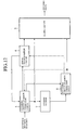
- Fig. 12 is a configuration diagram of a receiving side apparatus when the error correction code B is a systematic code, and the check of the error correction code B is subjected to correction coding, and transmitted from the transmission side after the data.
- a reference numeral 7 denotes storing section adapted to a decoded sequence decoded by the decoding circuit 5 of the error correction code A. The stored content thereof is outputted to the decoding circuit 8 of the error correction code B.
- Other components are similar to those of the configuration shown in Fig. 11.
- the coded sequence to be received, of the error correction code A including first transmitted data is entered to the decoding circuit 5 of the error correction code A, and subjected to decoding.
- the result of the decoding is stored in the storing section 7.
- the error determination circuit 6 determines whether an error is remaining in the correction result by the decoding circuit 5 of the error correction code A.
- the determination method can easily detect an error, for example if an error detection code is contained in the data. Also, for example, determination can be made based on the number of corrected errors in the block code, an error correction impossibility flag or the like.
- the error determination circuit 6 determines whether there are no errors in the data outputted from the decoding circuit 5 of the error correction code A. If it is determined by the error determination circuit 6 that there are no errors in the data outputted from the decoding circuit 5 of the error correction code A, then the result of the decoding by the decoding circuit 5 of the error correction code A is outputted as a decoded data sequence from the output circuit 9, and the sequence to be received, transmitted after the coded sequence of the error correction code A including the data, is annulled.
- the coded sequence of the error correction code A using the check sequence of the subsequent error correction code B as information is entered to the decoding circuit 5 of the error correction code A, and subjected to decoding.
- the check sequence of the error correction code B having been decoded by the error correction code A is entered, together with the data stored in the storing section 7, to the decoding circuit 8 of the error correction code B, and subjected to decoding.
- the result of the decoding by the decoding circuit 8 of the error correction code B is outputted as a decoded data sequence from the output circuit 9.
- interleaving can be carried out for the error correction codes A and B.
- the data sequence may be divided into a plurality of blocks, and a block having the error correction codes A and B as a pair may be transmitted by a plurality of times.
- the decoded result by the decoding circuit 8 of the error correction code B is entered to the determination circuit in a manner like that indicated by a chain line arrow of Fig. 12. If the presence of an error is determined, then the decoded result by the decoding circuit 8 of the error correction code B is entered to the decoding circuit 5 of the error correction code Ain a manner like that indicated by a dotted line arrow, and subjected to correction again. Error determination is made again by the error determination circuit 6 and, if there are no errors, then the correction result is outputted from the output circuit 9. If there is an error, as in the foregoing case, repeated decoding can be carried out, i.e., decoding is executed again by the decoding circuit 8 of the error correction code B.
- the two kinds of error correction codes i.e., the error correction codes A and B
- the error correction codes A and B are used.
- the error correction code B added to the code A three or more kinds of error correction codes can be used.
- the error correction code A as a block code such as a BCD code
- the error correction code B as the convolutional code of a systematic type, at the transmission side, for the convolutional code having a high correction capability, only a check part of the convolutional code can be easily transmitted later on, obtaining an advantage similar to that of the embodiment 3.
- the decoding circuit 8 of the error correction code B as a systematic convolutional code performs soft determination decoding in the configuration of the embodiment, then a soft determination value can also be given to the check part by the decoding circuit 5 of the error correction code A as a block code. Accordingly, it is possible to improve the correction capability of the decoding circuit 8 of the error correction code B as a systematic convolutional code. In addition, the improvement of the correction capability can be expected by executing repeated decoding.
- the transmission form was based on the assumption that the data length was constant. However, even if a data length is varied, as in the case of the embodiment 4 or 5, an operation similar to that of the embodiment 6 can be carried out by inserting the data length in the data
- the transmission system of the error correction method and apparatus was provided, for efficiently transmitting the data by using two or more kinds of error correction codes.
- a similar advantage can be obtained even if only one kind of error correction code is used.
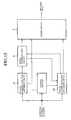
- Fig. 13 is a block diagram showing a transmission side apparatus used for an error correction method according to the ninth embodiment of the invention.
- a reference numeral 13 denotes an error correction coding circuit; 3 an output circuit for outputting a correction coded sequence including data; 4 a storing section for storing a part or all parts of the error correction coded sequence; and 14 a selection circuit for selecting the output of a coded sequence to the output circuit and the storing section 4.
- the data is subjected to error correction coding by the coding circuit 13 of the error correction code, and entered to the selection circuit 14.
- the selection circuit 14 based on the particular rule of a predetermined cycle, all or a part of the coded sequence is transmitted through the output circuit 3.
- all of the coded sequence of the data having been subjected to error correction coding by the coding circuit 13, or a part of the coded sequence based on the particular rule of a predetermined cycle is stored in the storing section 4.
- the data stored in the storing section 4 is transmitted through the output circuit 3.
- Fig. 14 shows a transmission frame based on the described operation. In this case, all parts of the coded sequence are stored in the storing section 4.
- a convolutional code of a rate 1/2 as an error correction code will be described.
- a convolutiuonal code of a rate 1/2 is set and, at the selection circuit 14, for example one having a rate 7/8 is selected from the coded sequence coming-in at a rate of 1/2 based on a punctured rule, and outputted from the output circuit 3.
- the punctured bit sequence of a rate 6/14 is stored in the storing section 4, and after all the data are transmitted as convolutional codes of a coding rate 7/8, the output circuit 3 is switched to the storing section 4, and the transmission is continued.
- Fig. 15 is a block diagram showing a receiving side apparatus according to the embodiment 9.
- a reference numeral 15 denotes the decoding circuit of an error correction code
- 6 an error determination circuit for determining whether or not an error remains in a decoding result by the decoding circuit 15 of the error correction code
- 7 a storing section for storing a sequence to be received, identical to one entered to the decoding circuit 15 of the error correction code
- 16 another decoding circuit of an error correction code
- 9 an output circuit.
- the sequence to be received is subjected to decoding by the decoding circuit 15 of the error correction code.
- the sequence to be received is stored in the storing section 7.
- the error determination circuit 6 determines whether or not an error remains in the correction result by the decoding circuit 15 of the error correction code.
- the method of determination can easily detect an error, for example if an error correction code is contained in the data. Also, for example, if the error correction code is a block code, then determination can be made based on the number of corrected errors, an error correction impossibility flag or the like.
- the error determination circuit 6 determines whether there are no errors in the data outputted from the decoding circuit 15 of the error correction code. If it is determined by the error determination circuit 6 that there are no errors in the data outputted from the decoding circuit 15 of the error correction code, the result of rate decoding by the decoding circuit 15 is outputted as a decoded data sequence from the output circuit 9, and the subsequent sequence to be received is annulled.
- determination may be made by the determination circuit 6 as to the presence of a remaining error in the data based on the decoded result by the decoding circuit 16 of the error correction code.
- a convolutional code of a rate 1/2 as an error correction code as in the case of the transmission side.
- a convolutional code of a rate 7/8 is transmitted, and subsequently the remaining coded sequence of a rate 6/14 is transmitted.
- the convolutional code of a rate 7/8 is subjected to decoding by the decoding circuit 15 of the error correction code 15, and the sequence to be received, of the convolutional code of a rate 7/8 is stored in the storing section 7.
- a subsequently received coded sequence of a rate 6/14 is inserted into the convolutional code of a rate 7/8 stored in the storing section 7, and the convolutional code of a rate 1/2 is subjected to decoding.
- interleaving can be carried out as in the conventional case.
- the coded sequence to be transmitted first, and the coded sequence to be subsequently transmitted may be one and the same.
- soft determination decoding can be carried out at the decoding circuit 15 and 16 of the error correction codes, making it possible to improve a correction capability.
- the decoding circuits 15 and 16 of the error correction codes were provided. However, since the error correction code is one and the same, one of the decoding circuit can be used for the other.
- Fig. 16 is a block diagram showing such an embodiment.
- a reference numeral 17 denotes the decoding circuit of an error correction code, serving also as another;
- 6 an error determination circuit for determining whether or not an error remains in the result of decoding performed by the decoding circuit 17 of the error correction code;
- 7 a storing section for storing a sequence to be received, entered to the decoding circuit 17 of the error correction code; and 18 an output circuit.
- a sequence to be received is subjected to decoding by the decoding circuit 17 of the error correction code according to a rate.
- the sequence to be received is stored in the storing section 7.
- the error determination circuit 6 determines whether or not an error remains in the correction result by the decoding circuit 17 of the error correction code.
- the method of determination can easily detect an error, for example if an error correction code is contained in the data. Also, for example, if the error correction code is a block code, determination can be made based on the number of corrected errors, an error correction impossibility flag or the like.
- the error determination circuit 6 determines whether there are no errors in the data outputted from the decoding circuit 17 of the error correction code. If it is determined by the error determination circuit 6 that there are no errors in the data outputted from the decoding circuit 17 of the error correction code, the result of decoding performed by the decoding circuit 17 of the error correction code is outputted as a decoded data sequence from the output circuit 18, and a subsequent sequence to be received is annulled.
- the sequence to be received, stored in the storing section 7 is returned to the decoding circuit 17 of the error correction code, and the subsequently received error correction coded sequence is inserted therein. Then, the returned sequence is subjected to decoding by the decoding circuit 17 of the error correction code according to the rate, and the result of the decoding is outputted as a decoded data sequence from the output circuit 8. Also, in this case, determination may be made by the error determination circuit 6 as to the presence of a remaining error in the data.
- the apparatus having a configuration dedicated to the error correction method.
- similar processing can be easily realized by using an apparatus having a general-purpose computer, e.g., a personal computer (PC). and a general-purpose memory.
- a general-purpose computer e.g., a personal computer (PC).
- PC personal computer
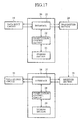
- FIG. 17 is a block diagram showing such an embodiment.
- a reference numeral 19 denotes data input circuit such as a digital camera or the like; 20 a transmission side general-purpose computing section; 21 an interface for transferring data between the inside and the outside of the transmission side general-purpose computing section 20; 22 computation/control section such as a general-purpose processor or the like in the transmission side general-purpose computing section 20; 23 a storing section such as the one represented by a semiconductor memory in the transmission side general-purpose computing section 20; and 24 a transmitter section such as a portable telephone set or the like.
- These components constitute a transmission side apparatus.
- a reference numeral 25 denotes receiver section such as a portable telephone set; 26 a receiving side general-purpose computing section; 27 an interface in the receiving side general-purpose computing section 26; 28 a computation/control section in the receiving side general-purpose computing section 26; 29 a storing section in the receiving side general-purpose computing section 26; and 30 a data output circuit such as a display or the like.
- receiver section such as a portable telephone set
- 26 a receiving side general-purpose computing section
- 27 an interface in the receiving side general-purpose computing section 26
- 28 a computation/control section in the receiving side general-purpose computing section 26
- 29 a storing section in the receiving side general-purpose computing section 26
- 30 a data output circuit such as a display or the like.
- processing similar to that of the embodiment 1 is executed by the general-purpose computing section 20.
- data obtained by the data input circuit 19 is stored in the storing section 23 through the interface 21, and the computation/control section 22 of the general-purpose computing section 20.
- processing similar to that of the coding circuit 1 and 2 of the error correction codes A and B shown in Fig. 1 is executed by using the computation/control section 22 and the storing section 23.
- a coded sequence is outputted to the transmitter section 24 through the interface 21 of the general-purpose computing section 20.
- control is performed by the computation/control section 22 such that the coded sequence of the error correction code A including the data, stored in the storing section 23, is outputted first, and the coded sequence of the error correction code B is subsequently transmitted.
- error correction coding processing and output processing to the transmitter section 24 may be executed in a time division manner or simultaneously.
- the transmitter section 24 makes connection to an opposite party for transmission, namely the receiver section, and transmits the coded sequence outputted from the general-purpose computing section 20.
- the general-purpose computing section 26 of the receiving side is prepared, and a sequence to be received is received from the receiver section 25 through the interface 27 of the general-purpose computing section 26.
- the received sequence to be received is temporarily stored in the storing section 29 by the computation/control section 28.
- the computation/control section 28 determines whether or not there is an error in the decoded result stored in the storing section 29.
- the determination method can easily detect an error, for example if an error detection code is contained in the data. Also, for example, determination can be made based on the number of corrected errors in the block code, an error correction impossibility flag or the like.
- the computation/control section 28 stops the receiving processing of the receiver section 25 through the interface 27, and the decoded data stored in the storing section 29 is outputted through the interface 27 to the data output circuit 30.
- the receiving operation is continued.
- the coded sequence of the error correction code B is set, the error correction code B is subjected to decoding by the computation/control section 28 also using the decoded data decoded by the error correction code A, and the result thereof is stored in the storing section 29.
- the computation/control section 28 stops the receiving processing of the receiver section 25 through the interface 27, and the decoded data stored in the storing section 29 is outputted through the interface 27 to the data output circuit 30.
- interleaving can be carried out for the error correction codes A and B by using the transmission side general-purpose computing section 20 and the receiving side general-purpose computing section 26.
- the data sequence can be divided into a plurality of blocks, and a block having the error correction codes A and B as a pair can be transmitted by a plurality of times.
- the receiving side general-purpose computing section 26 can carry out repeated decoding. Specifically, determination is made by the computation/control section 28 as to the presence of an error in the correction result of the error correction code B stored in the storing section 29, and if the presence of an error is determined, then the decoding of the error correction code A is executed again, and determination processing is executed again, whereas if there is still an error, then the decoding of the error correction code B is executed.
- the data input circuit 19, the transmission side general-purpose computing section 20, and the transmitter section 24 were separated.
- the transmission side general-purpose computing section 20 can incorporate the data input circuit 19, and the transmitter section 24.
- the receiving side general-purpose computing section 26 can incorporate the receiver section 25 and the data output circuit 30.
- the error correction code A was a block code composed of a plurality of code words
- the error correction code B was the convolutional code of a systematic type.
- these can be set as general concatenated codes.
- transmitter section takes a configuration similar to that of Fig. 1 or Fig. 9. But any transmission order can be set for the error correction codes A and B.
- the operation at the receiving side is similar to that of the embodiment 3 or 7. However, it is not necessary to execute error detection for the decoded data of the error correction code A subjected to first decoding. In other words, it is not necessary to provide error determination circuit 6 like that shown in Fig. 3 or Fig. 12.
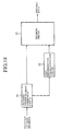
- Fig. 18 shows an configuration example thereof, in which a reference numeral 31 denotes the decoding circuit of an error correction code A as an internal code; 32 a soft determination value generation circuit for generating a soft determination value based on the number of corrected errors outputted from the decoding circuit of the error correction code A; and 33 decoding circuit for executing soft determination decoding by an error correction code B as an external code.
- a sequence to be received composed of a plurality of code words, is subjected to decoding by the decoding circuit 31 of the internal code, and the number of corrected errors for each code word is obtained.
- the correction impossibility can be set to be distinguished, for example t+1 with respect to the number of correction possible errors t .
- the data obtained by the decoding circuit 3 of the internal code is entered to the decoding circuit 33 of the external code, and the number of corrected errors for each code word is also entered to the soft determination generation circuit 32.
- a soft determination value is generated according to the number of corrected errors.
- the number of corrected errors is within a correction possible range, there should be no errors in the decoded data.
- correction may possibly be erroneous.
- a probability of erroneous correction is smaller.
- a soft determination value is set corresponding to hard determination decoded data in accordance with the number of corrected errors including the correction possible range. Since an erroneous correction probability with respect to the number of corrected errors is exponential, a difference should preferably be generated for a soft determination value with respect to the number of corrected errors. For example, if a soft determination is t+1-m with respect to the number m of corrected errors equal to the number of errors, then conversion can be made only by a shifting operation on a connection.
- the decoding circuit 33 of the external code executes soft determination decoding, e.g., Viterbi decoding, by simultaneously using the decoded data of the internal code, and the soft determination value generated based on the number of corrected errors corresponding to the decoded data, and then outputs the decoded data.
- soft determination decoding e.g., Viterbi decoding
- the adjacent decoded data sequence of the decoding circuit 33 of the external code have been subjected to interleaving such that the code words of the internal code can be different.
- soft determination decoding can be realized without obtaining any reliability information from the receiving side, and without controlling a reliability information addition mode for the decoded result of the internal code.
- the internal code was a block code
- the external code was a systematic convolutional code.
- any code can be used for the internal code as long as it enables a decoding state to be obtained for the decoded data from a plurality of code words, and also any can be used for the external code as long as it facilitates soft determination decoding.
- decoded data may be only a part of the internal code with respect to the external code.
- soft determination is not obtained from the decoded data of the internal code, and soft determination information may be added for the coded sequence of the external code such that hard determination data can be valid, and reliability substantially equal to that of the correction impossible decoded data of the internal code can be set.
- an error correction coded sequence having small redundancy can be transmitted first, and an error correction coded sequence including data having a large correction capability can be subsequently transmitted.
- the data can be transmitted while protecting the data from an error with a short transmission bit length, and a strong error protection can be provided.
- the error correction coded sequence transmitted first including the data is subjected to decoding. If the presence of no errors in the decoding result is determined, the result is immediately outputted. If the presence of a remaining error is determined, the error correction coded sequence subsequently transmitted is subjected to decoding, and outputted. Accordingly, the error correction coded sequence transmitted first can be set as one including data, having small redundancy; and the error correction coded sequence transmitted subsequently as one having a large correction capability. Therefore, the data can be reproduced faster if the number of errors is small on the transmission path. Even if the number of errors is large, with transmission time substantially equal to that of the conventional case, a correction capability equal or exceeding that of the conventional case can be obtained by using the previous result of decoding.
- the coding circuit can be the one for protecting the data to be transmitted by the error correction code having a large correction capability; and the one with the error correction code having small redundancy for protecting the data to be transmitted and the check of the error correction code having a large correction capability.
- the data and the error correction coded sequence having a large correction capability can be entered to the coding circuit of the error correction code having small redundancy.
- the error correction coded sequence having a large correction capability, to be transmitted later can be stored.
- the data can be transmitted while the data is protected from an error with a short transmission bit length, and a strong error protection can be provided.
- decoding, storing and output circuit are respectively provided as follows: first decoding circuit for decoding an error correction code having small redundancy; storing section for storing the data thus decoded in the decoding circuit; second decoding circuit for outputting decoded data from the decoded data stored in the storing section and an error correction coded sequence having a large correction capability, outputted from the decoding circuit for decoding the error correction code having small redundancy; and output circuit for immediately outputting the result thereof if the determination circuit determines the presence of no errors in the decoded data of the first decoding circuit.
- the data can be reproduced faster if the number of errors is small on the transmission path. Even if the number of errors is large, a very strong correction capability can be obtained by using the previously decoding result.
- the error correction method and apparatus of the invention comprise: the coding circuit for protecting data to be transmitted by one error correction code; the transmission procedure circuit for first transmitting only a part of the coded sequence including the data, and subsequently transmitting the remaining error correction coded sequence; and the storing section for storing the error correction coded sequence for subsequent transmission.
- the data can be transmitted while the data is protected from an error with a short transmission bit length by one coding circuit, and a strong error protection can be provided.
- the apparatus comprises: the decoding circuit for executing decoding by a part of the error correction coded sequence including the data transmitted first; the storing section for storing the sequence to be received thereof; another decoding circuit for synthesizing the remaining error correction coded sequence subsequently sent-in, with a part of the error correction coded sequence including the data first transmitted, and then decoding it; the determination circuit for decoding the error correction coded sequence including the data first transmitted, and determining whether or not there are any errors in the decoded result; and the output circuit for immediately outputting the result thereof if the presence of no errors is determined by the determination circuit.
- the decoding circuit for executing decoding by a part of the error correction coded sequence including the data transmitted first; the storing section for storing the sequence to be received thereof; another decoding circuit for synthesizing the remaining error correction coded sequence subsequently sent-in, with a part of the error correction coded sequence including the data first transmitted, and then decoding it; the determination circuit for decoding the error correction coded sequence including the data first transmitted,
- the coding circuit of the concatenated code includes: the coding circuit of the inner code generated by the coded sequence composed of a plurality of code words; and the coding circuit of the external code subjected to, e.g., soft determination for generating a convolutional code.
- the coding circuit of the concatenated code includes: the coding circuit of the inner code generated by the coded sequence composed of a plurality of code words; and the coding circuit of the external code subjected to, e.g., soft determination for generating a convolutional code.
- the decoding circuit of the concatenated code includes: the decoding circuit of the internal code for decoding the coded sequence composed of a plurality of code words, and outputting the number of errors; and the decoding circuit of the external code for executing decoding based on the rule of the convolutional code by using the decoded data of the internal code, and the number of errors.
Landscapes
- Engineering & Computer Science (AREA)
- Computer Networks & Wireless Communication (AREA)
- Signal Processing (AREA)
- Physics & Mathematics (AREA)
- Probability & Statistics with Applications (AREA)
- Theoretical Computer Science (AREA)
- Mathematical Physics (AREA)
- Quality & Reliability (AREA)
- Error Detection And Correction (AREA)
- Detection And Prevention Of Errors In Transmission (AREA)
- Detection And Correction Of Errors (AREA)
Applications Claiming Priority (2)
| Application Number | Priority Date | Filing Date | Title |
|---|---|---|---|
| JP2000225421 | 2000-07-26 | ||
| JP2000225421A JP2002043953A (ja) | 2000-07-26 | 2000-07-26 | 誤り訂正方法及び誤り訂正装置 |
Publications (1)
| Publication Number | Publication Date |
|---|---|
| EP1176748A2 true EP1176748A2 (fr) | 2002-01-30 |
Family
ID=18719199
Family Applications (1)
| Application Number | Title | Priority Date | Filing Date |
|---|---|---|---|
| EP01117502A Withdrawn EP1176748A2 (fr) | 2000-07-26 | 2001-07-20 | Méthode et appareil pour la correction d'erreurs |
Country Status (4)
| Country | Link |
|---|---|
| US (1) | US20020016944A1 (fr) |
| EP (1) | EP1176748A2 (fr) |
| JP (1) | JP2002043953A (fr) |
| CN (1) | CN1335697A (fr) |
Families Citing this family (19)
| Publication number | Priority date | Publication date | Assignee | Title |
|---|---|---|---|---|
| EP1554812B1 (fr) * | 2002-10-15 | 2006-12-06 | Koninklijke Philips Electronics N.V. | Systeme et procédé de recouvrement d'erreur pour la diffusion en continu de donnees video fgs codees dans un réseau internet |
| JP2004159017A (ja) * | 2002-11-05 | 2004-06-03 | Ntt Docomo Inc | 移動通信システム、及びこれに用いて好適な無線局 |
| KR20040046649A (ko) | 2002-11-28 | 2004-06-05 | 삼성전자주식회사 | 에러 정정을 위한 부호화 장치 및 방법과 복호화 장치 및방법 |
| US7155655B2 (en) * | 2003-07-22 | 2006-12-26 | Telefonaktiebolaget Lm Ericsson (Publ) | Adaptive hybrid ARQ algorithms |
| US7509556B2 (en) * | 2003-11-20 | 2009-03-24 | Seagate Technology Llc | Method and apparatus for combining output of different type interleavers based on an input data sequence to obtain a combined output |
| JP2006041568A (ja) * | 2004-07-22 | 2006-02-09 | Hitachi Kokusai Electric Inc | データ伝送装置およびデータ伝送方法 |
| KR100740209B1 (ko) * | 2005-10-21 | 2007-07-18 | 삼성전자주식회사 | 디지털 방송 수신 시스템 및 그 신호 처리 방법 |
| JP2008085939A (ja) * | 2006-09-29 | 2008-04-10 | Oki Electric Ind Co Ltd | 通信装置 |
| KR20080070366A (ko) * | 2007-01-26 | 2008-07-30 | 엘지전자 주식회사 | 데이터 인코딩/디코딩 방법 및 장치와, 데이터 기록/재생방법 및 장치 |
| JP5507813B2 (ja) * | 2007-02-16 | 2014-05-28 | パナソニック株式会社 | 送信装置及び受信装置 |
| WO2008099617A1 (fr) * | 2007-02-16 | 2008-08-21 | Panasonic Corporation | Dispositif de transmission, dispositif de réception, codeur et procédé de codage |
| JP5638956B2 (ja) * | 2008-10-23 | 2014-12-10 | パナソニック インテレクチュアル プロパティ コーポレーション オブアメリカPanasonic Intellectual Property Corporation of America | 無線送信装置、無線受信装置、符号化データ送信方法、及び符号化データ受信方法 |
| JP2010204828A (ja) * | 2009-03-02 | 2010-09-16 | Renesas Electronics Corp | データ保護回路及び方法、並びにデータ処理装置 |
| JP5382779B2 (ja) * | 2009-03-13 | 2014-01-08 | オムロンオートモーティブエレクトロニクス株式会社 | 通信システム、通信方法、および携帯機 |
| CN101882974A (zh) * | 2010-06-12 | 2010-11-10 | 中兴通讯股份有限公司 | 一种高速串行信号实时在线检测的方法和系统 |
| JP5364807B2 (ja) * | 2011-06-08 | 2013-12-11 | パナソニック株式会社 | メモリコントローラ及び不揮発性記憶装置 |
| JP2019057752A (ja) * | 2017-09-19 | 2019-04-11 | 東芝メモリ株式会社 | メモリシステム |
| WO2020115874A1 (fr) * | 2018-12-06 | 2020-06-11 | 三菱電機株式会社 | Dispositif et procédé de décodage de correction d'erreur |
| CN115019862B (zh) * | 2021-03-04 | 2026-01-13 | 瑞昱半导体股份有限公司 | 静态随机存取存储器的纠错电路的验证方法 |
Family Cites Families (11)
| Publication number | Priority date | Publication date | Assignee | Title |
|---|---|---|---|---|
| DE4202140A1 (de) * | 1992-01-27 | 1993-07-29 | Thomson Brandt Gmbh | Verfahren zur uebertragung digitaler audio-signale |
| US5463641A (en) * | 1993-07-16 | 1995-10-31 | At&T Ipm Corp. | Tailored error protection |
| US5872798A (en) * | 1994-02-16 | 1999-02-16 | U.S. Philips Corporation | Error correctable data transmission method and device based on semi-cyclic codes |
| US6012839A (en) * | 1995-06-30 | 2000-01-11 | Quantum Corporation | Method and apparatus to protect data within a disk drive buffer |
| US6405338B1 (en) * | 1998-02-11 | 2002-06-11 | Lucent Technologies Inc. | Unequal error protection for perceptual audio coders |
| US6370666B1 (en) * | 1998-12-02 | 2002-04-09 | Agere Systems Guardian Corp. | Tuning scheme for error-corrected broadcast programs |
| US6754290B1 (en) * | 1999-03-31 | 2004-06-22 | Qualcomm Incorporated | Highly parallel map decoder |
| US6795507B1 (en) * | 1999-09-30 | 2004-09-21 | Skyworks Solutions, Inc. | Method and apparatus for turbo decoding of trellis coded modulated signal transmissions |
| US6606724B1 (en) * | 2000-01-28 | 2003-08-12 | Conexant Systems, Inc. | Method and apparatus for decoding of a serially concatenated block and convolutional code |
| US6747827B1 (en) * | 2000-03-27 | 2004-06-08 | Texas Instruments Incorporated | Error correction codes applied variably by disk zone, track, sector, or content |
| US6675344B1 (en) * | 2000-05-01 | 2004-01-06 | Hewlett-Packard Development Company, L.P. | Multiple ECC schemes to improve bandwidth |
-
2000
- 2000-07-26 JP JP2000225421A patent/JP2002043953A/ja active Pending
-
2001
- 2001-07-20 EP EP01117502A patent/EP1176748A2/fr not_active Withdrawn
- 2001-07-25 CN CN01133150.XA patent/CN1335697A/zh active Pending
- 2001-07-25 US US09/911,735 patent/US20020016944A1/en not_active Abandoned
Also Published As
| Publication number | Publication date |
|---|---|
| US20020016944A1 (en) | 2002-02-07 |
| JP2002043953A (ja) | 2002-02-08 |
| CN1335697A (zh) | 2002-02-13 |
Similar Documents
| Publication | Publication Date | Title |
|---|---|---|
| EP1176748A2 (fr) | Méthode et appareil pour la correction d'erreurs | |
| US5416787A (en) | Method and apparatus for encoding and decoding convolutional codes | |
| US20060153250A1 (en) | Coding of data stream | |
| EP0981218A2 (fr) | Systeme de codage correcteur d'erreurs | |
| JPH0555932A (ja) | 誤り訂正符復号化装置 | |
| JP3613448B2 (ja) | データ伝送方法、データ伝送システム、送信装置および受信装置 | |
| US6452985B1 (en) | Viterbi decoding apparatus and Viterbi decoding method | |
| US6516439B2 (en) | Error control apparatus and method using cyclic code | |
| CN100508440C (zh) | 接收移动无线信号时的译码及循环冗余校验的并行处理的方法和装置 | |
| JP4071879B2 (ja) | 誤り検出器、この誤り検出器を備えた通信システム、および誤り検出方法 | |
| JPWO2001037432A1 (ja) | 巡回符号を用いた誤り制御装置および方法 | |
| US7284185B2 (en) | Puncturing/depuncturing using compressed differential puncturing pattern | |
| US6985726B2 (en) | Method of blind transport format detection | |
| US20050268205A1 (en) | Method and apparatus for decoding inner and outer codes in a mobile communication system | |
| US20030018942A1 (en) | Common memory device and controlling method thereof | |
| US20020034225A1 (en) | Coding of a data stream | |
| US6385753B1 (en) | Punctured Viterbi decoding method | |
| CN100426713C (zh) | 错误修正处理的通信方法及应用该通信方法的通信装置 | |
| JP2715398B2 (ja) | 誤り訂正符復号化装置 | |
| JP3237700B2 (ja) | 誤り検出方法及び誤り検出システム | |
| US8255757B2 (en) | Apparatus and method for error correction in mobile wireless applications incorporating erasure table data | |
| US6651211B1 (en) | Method of mobile telecommunications | |
| JPS62116019A (ja) | 符号化および復号処理のためのディジタル共用回路 | |
| EP0851591B1 (fr) | Processeur des données et procédé de traitement des données | |
| JP2001339466A (ja) | 可変レート符号受信装置 |
Legal Events
| Date | Code | Title | Description |
|---|---|---|---|
| PUAI | Public reference made under article 153(3) epc to a published international application that has entered the european phase |
Free format text: ORIGINAL CODE: 0009012 |
|
| AK | Designated contracting states |
Kind code of ref document: A2 Designated state(s): AT BE CH CY DE DK ES FI FR GB GR IE IT LI LU MC NL PT SE TR |
|
| AX | Request for extension of the european patent |
Free format text: AL;LT;LV;MK;RO;SI |
|
| STAA | Information on the status of an ep patent application or granted ep patent |
Free format text: STATUS: THE APPLICATION HAS BEEN WITHDRAWN |
|
| 18W | Application withdrawn |
Effective date: 20050916 |