EP1176784A2 - Vorrichtungen, Computerprogrammprodukt und Verfahren zur Verwaltung einer Datenübertragung - Google Patents
Vorrichtungen, Computerprogrammprodukt und Verfahren zur Verwaltung einer Datenübertragung Download PDFInfo
- Publication number
- EP1176784A2 EP1176784A2 EP01117543A EP01117543A EP1176784A2 EP 1176784 A2 EP1176784 A2 EP 1176784A2 EP 01117543 A EP01117543 A EP 01117543A EP 01117543 A EP01117543 A EP 01117543A EP 1176784 A2 EP1176784 A2 EP 1176784A2
- Authority
- EP
- European Patent Office
- Prior art keywords
- data
- connection
- physical
- pdu
- data connection
- Prior art date
- Legal status (The legal status is an assumption and is not a legal conclusion. Google has not performed a legal analysis and makes no representation as to the accuracy of the status listed.)
- Withdrawn
Links
Images



Classifications
-
- H—ELECTRICITY
- H04—ELECTRIC COMMUNICATION TECHNIQUE
- H04L—TRANSMISSION OF DIGITAL INFORMATION, e.g. TELEGRAPHIC COMMUNICATION
- H04L12/00—Data switching networks
- H04L12/54—Store-and-forward switching systems
- H04L12/56—Packet switching systems
- H04L12/5691—Access to open networks; Ingress point selection, e.g. ISP selection
- H04L12/5692—Selection among different networks
-
- H—ELECTRICITY
- H04—ELECTRIC COMMUNICATION TECHNIQUE
- H04L—TRANSMISSION OF DIGITAL INFORMATION, e.g. TELEGRAPHIC COMMUNICATION
- H04L67/00—Network arrangements or protocols for supporting network services or applications
- H04L67/01—Protocols
- H04L67/04—Protocols specially adapted for terminals or networks with limited capabilities; specially adapted for terminal portability
-
- H—ELECTRICITY
- H04—ELECTRIC COMMUNICATION TECHNIQUE
- H04L—TRANSMISSION OF DIGITAL INFORMATION, e.g. TELEGRAPHIC COMMUNICATION
- H04L67/00—Network arrangements or protocols for supporting network services or applications
- H04L67/14—Session management
-
- H—ELECTRICITY
- H04—ELECTRIC COMMUNICATION TECHNIQUE
- H04L—TRANSMISSION OF DIGITAL INFORMATION, e.g. TELEGRAPHIC COMMUNICATION
- H04L69/00—Network arrangements, protocols or services independent of the application payload and not provided for in the other groups of this subclass
- H04L69/08—Protocols for interworking; Protocol conversion
- H04L69/085—Protocols for interworking; Protocol conversion specially adapted for interworking of IP-based networks with other networks
-
- H—ELECTRICITY
- H04—ELECTRIC COMMUNICATION TECHNIQUE
- H04L—TRANSMISSION OF DIGITAL INFORMATION, e.g. TELEGRAPHIC COMMUNICATION
- H04L69/00—Network arrangements, protocols or services independent of the application payload and not provided for in the other groups of this subclass
- H04L69/16—Implementation or adaptation of Internet protocol [IP], of transmission control protocol [TCP] or of user datagram protocol [UDP]
- H04L69/161—Implementation details of TCP/IP or UDP/IP stack architecture; Specification of modified or new header fields
- H04L69/162—Implementation details of TCP/IP or UDP/IP stack architecture; Specification of modified or new header fields involving adaptations of sockets based mechanisms
-
- H—ELECTRICITY
- H04—ELECTRIC COMMUNICATION TECHNIQUE
- H04L—TRANSMISSION OF DIGITAL INFORMATION, e.g. TELEGRAPHIC COMMUNICATION
- H04L69/00—Network arrangements, protocols or services independent of the application payload and not provided for in the other groups of this subclass
- H04L69/16—Implementation or adaptation of Internet protocol [IP], of transmission control protocol [TCP] or of user datagram protocol [UDP]
-
- H—ELECTRICITY
- H04—ELECTRIC COMMUNICATION TECHNIQUE
- H04L—TRANSMISSION OF DIGITAL INFORMATION, e.g. TELEGRAPHIC COMMUNICATION
- H04L69/00—Network arrangements, protocols or services independent of the application payload and not provided for in the other groups of this subclass
- H04L69/30—Definitions, standards or architectural aspects of layered protocol stacks
- H04L69/32—Architecture of open systems interconnection [OSI] 7-layer type protocol stacks, e.g. the interfaces between the data link level and the physical level
- H04L69/322—Intralayer communication protocols among peer entities or protocol data unit [PDU] definitions
- H04L69/329—Intralayer communication protocols among peer entities or protocol data unit [PDU] definitions in the application layer [OSI layer 7]
Definitions
- the invention relates to devices, methods and a computer program product to manage data transfer via a connection-oriented data connection.
- TCP Transmission Protocol
- IP Internet Protocol
- HTTP Hypertext Transfer Protocol
- WWW World Wide Web
- HTTP is a client-server protocol.
- the user needs a client (e.g. a computer, or a (Mobile) phone) on which a so-called web browser as client software running.
- the web browser requests the desired web page at Opening a connection from a web server to this back to the web browser and the connection to the browser closes.
- HTML Hypertext Mark-up Language
- dHTML Dynamic HTML
- CGI Common Gateway Interface
- ASP Active Server Pages
- the Internet is based on packet switching technology.
- the data that Shipped over the Internet are packaged individually packed, which are sent independently. I.a. has a package less than 1500 characters. Each package contains one checksum calculated by the sender from the data to be sent, with which can be determined at the receiving location whether transmission errors appeared.
- the recipient also calculates one from the received data Checksum, which is compared with the transferred checksum. If the checksums do not match, the sender will order asked to resubmit the package.
- the invention has the task, on the other hand, novel devices and methods of managing data transmission as well as a to provide a novel computer program product.
- a method of managing data transfer via a connection-oriented data connection, in particular a cellular telephone connection comprising the following steps: Converting user data to be transmitted into successive ones Data packets; Capture the transmission quality of the data transmission during the transmission of the user data; and customize depending on the amount of user data transmitted per unit of time of the recorded transmission quality during the transmission of the Payload.
- a method of transferring data over a physical connection-oriented data connection comprising the steps of: determining of characteristic for the entire data connection Identification features, in particular a software identification number; Assign a physical connection to a logical data connection based on the determined characteristic Identifiers; and save existing ones logical data connections based on their associated identification features.
- command code sections includes, through which the implementation of the above. process is caused when the computer program on a terminal, in particular a computer and / or a telephone is running.
- Computer program product used in the claims it should be mentioned that this includes a computer program or a Computer program module is to be understood, which is through storage (e.g. on a magnetic storage medium or in a volatile or non-volatile semiconductor memory of the above Device, in particular a computer and / or a telephone) or by signals that come through a network, especially that Internet that is shipped is embodied. It takes that Computer program not in an immediately executable form rather, it can also be in one for installation are on the computer and / or telephone, being packed, encrypted, of course, for one any dispatch over a network divided into packets and with transmission-related headers can be provided, etc.
- the transmission quality e.g. are detected in that the data packets are received by one Receiver, e.g. a server (or alternatively one Client) computer, confirmation signals to the device, in particular a client (or alternatively a server) computer, be sent.
- the recipient advantageously confirms separately for every single data packet, or for a certain number of times Data packets of their correct arrival.
- This can Receiver e.g. in a conventional manner by evaluating im Determine the checksum bits contained in the data packet.
- one Confirmation signal can be an incorrectly received data packet alternatively e.g. also indicated by sending an error signal become.
- the confirmation signal (or the Error signal) identifying the associated data packet Bit sequence.
- the transmission quality is preferably based on the ratio between the number sent out and the number as correct Confirmed or error-free received data packets determined. There is "bad” transmission quality if this ratio falls below a specified target value. Alternatively, the transmission quality can already be considered as be rated “bad” if a single data packet is not arrives correctly.
- the amount of user data transmitted per unit of time is determined reduced. This is preferably done in that the data packet length downsized, while reducing the amount of data in a packet contained user data is reduced. This remains advantageous the amount of control data contained in each data packet is constant.
- the invention is particularly preferably implemented in software. It is advantageous both on the client and on special software is installed on the server computer, the command code sections includes which function calls a TCP / IP Socket interface, e.g. a Windows socket interface (or alternatively any other internet interface) map in such a way that the above Procedures are carried out.
- a TCP / IP Socket interface e.g. a Windows socket interface (or alternatively any other internet interface) map in such a way that the above Procedures are carried out.
- the interface of the TCP / IP protocol is from the software according to the invention in a the above. steps effective, original protocol translated. Because of the engagement The TCP / IP interface can handle a variety of client / server applications are supported without the inventive Software special adjustments would be necessary.
- the data transmission according to the invention advantageously runs as follows from: Should from a conventional, on the client (or the Server) loaded software program from data to the server (or the client) is transmitted, this calls the (TCP / IP) internet interface (i.e. a corresponding software program) on.
- the client (or server) software according to the invention recognizes that data is sent to a special server (or client) are to be transmitted on which the corresponding, inventive Server (or client) software is installed - for example via its Internet address, telephone number, etc.
- the program according to the invention effects the aforementioned Illustration of the calls of the TCP / IP socket interface, so that the above-mentioned Process steps are effected, e.g. by corresponding Control a modem.
- Data transmission is preferred according to the two inventive Aspects managed.
- the one transmitted per unit of time Amount of user data from the transmission quality during transmission the user data is adapted and, for example, after a (wanted or unwanted) termination of a physical data connection and after establishing a new physical data connection on the basis of the characteristic quantities of the new data connection an assignment to an existing one logical data connection (a still running or with the network related application program, e.g. the still running web browser on a client computer, etc.) searched becomes.
- the connection is preferably canceled the corresponding server (or the client) is automatically re-selected. This recognizes e.g. the serial number of the client (or the server) software, the phone number e.g.
- the mobile device or its IMEI number (mobile device number) that it is to resume a logical data connection after a Termination of the underlying physical data connection is.
- IMEI number mobile device number
- the occurrence of a Connection termination of the physical data connection e.g. at a telephone connection
- the client or server computer received Busy signal or a network status can be determined.
- the physical data connection is particularly advantageous in poor transmission quality automatically canceled, and then automatically rebuilt.
- the connection can be broken e.g. can be achieved by causing the modem to corresponding telephone connection end character at the corresponding Send client or server.
- the connection rebuilt - e.g. by sending the phone line of the server or of the client corresponding telephone connection dialing signs (i.e. by dialing the server's phone number or of the client).
- the connection often greatly improves the transmission quality.
- the administration devices according to the invention are preferred data transmission with a mobile phone and / or designed a portable computer on which the invention Software is installed.
- connection automatically canceled - for example by sending an end call sign.
- connection is preferred if this is according to the TCP / IP protocol would actually be closed, nevertheless a predetermined period of time long (e.g. 1 minute, 30 seconds or 10 seconds) maintained. This eliminates unnecessary selection processes avoided.
- the program system 1 shows a schematic representation of the protocol layers of the program system 1 according to the invention (Mobile Manager).
- the program system 1 provides a Windows socket 4a, 4b based environment for client / server applications 5, 6.
- This environment is for the use of cellular services such as Modacom, GSM or UMTS aligned.
- the program system 1 consists of a server component 2 and a client component 3. These represent client / server applications 5, 6 a communication interface Base of Windows Sockets 4a, 4b available. This can supports a large number of common client / server applications 5, 6 without adjustments.
- the client component 3 of the program system according to the invention 1 are function calls of the socket interface 4a on mobile medium (radio data transmission) mapped.
- This is done by the client component 3 a modem, e.g. a Modacom modem 7 (or a GSM modem 8, or an ISDN card 9) controlled.
- This transmits the data to an associated base station 10 (or to a modem server 11, or to an ISDN server 12).
- the client / server application 5, 6 has no knowledge of the respective transmission medium.
- the server component 2 of the Base station 10 or from the modem server 11, or from the ISDN server 12
- the server application 6 and the Server component 2 are usually located in a LAN environment, into which then the TCP connections of the client applications 5 can be switched through.
- the MOBILEmanager.dll process implements all API functions the Winsock 2.0 Service Provider Interface.
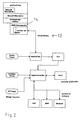
- the communication between the processes MOBILEmanager.dll 14 and MOBILEmanager.exe takes place via shared memory 13, as shown in FIG. 2.
- the RLLP Radio Link Level protocol realizes error detection and, if necessary, correction during data transmission in radio networks.
- the Scrdaemon process is the core process. It manages all TCP connections from all connected modems, regardless of whether GSM, ISDN or Modacom is used as a service becomes.
- the SCR protocol standard Context routing).
- the process is over Scrdaemon the protocol X.25 (DATEX-P) with the respective Modacom service Provider connected.
- the SCR protocol makes it possible to use a logical X.25 connection to control any number of Modacom modems.
- This Process forms the RLLP used on the physical link Protocol based on the SCR protocol.
- the connection to the process Scrdaemon is made using the TCP protocol.
- the Process Scrproc is activated when the client component 3 dialed in.
- the core module processes the RTP protocol and manages all of them TCP connections.
- the SCR module is used to control the modems. It processes the SCR protocol. As a medium for SCR connections can use TCP and X.25.
- the user data of the PDU normally follow the first byte. Compressed user data are set by bit No. 7 in the first byte is displayed. Since it is when using the RTP protocol with GSM modem to duplicate PDU, there is Possibility of adding an optional serial number in the data PDU transfer.
- sequence numbers is during the Established a logical RTP connection. Be for an RTP connection uses serial numbers, so these are located in the second byte of the PDU and the user data then start from third byte.
- FIG. 3 shows a schematic illustration of states occurring in the RTP protocol of FIG. 1.
- the RTP protocol is carried out separately for each individual TCP connection, ie for each socket. The only exception to this is Command No. 9 ( Extended Connect ).
- the individual states in the protocol therefore always correspond to the state of a single socket.
- a socket is in the IDLE state after it has been allocated by the socket system call.
- Fig. 4 shows a schematic representation of sub-states of the IDLE state.
- the transition to connecting takes place when the connect system function is called.
- 5 shows a schematic representation of sub-states of the CONNECTING state.
- connection establishment request is transmitted to the MOBILEmanager server in a Connect Request PDU. After receiving this PDU, the server will try to set up the TCP connection accordingly. The result is sent back to the client system in the form of a Connect Confirmation PDU. This PDU contains the result for calling the system function connect . If the TCP connection from the server to an application is successfully established, the socket changes to the CONNECTED state.
- Fig. 6 shows a schematic representation of its sub-states.
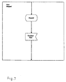
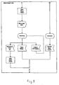
- FIG. 7 shows a schematic illustration of sub-states of the FLOW-STOPPED state shown in FIG. 6. 8 shows a schematic representation of sub-states of the DISCONNECTING state.
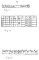
- the structure of a PDU or a data packet 15 is shown in FIG. 9 shown. All PDUs start with an STX character and end with an ETX symbol. Length information is not included that there is no block length restriction.
- checksum calculation starts after the STX character and contains all characters between STX characters and checksum.
- the STX character is followed by a byte with PDU-specific information, then the actual user data optionally follow.
- the total length of the PDU thus results from the length of the user data plus 7 bytes of protocol information.
- the 8 bits of the PDU type are organized as shown in FIG. 10.
- the DATA PDU is always sent with the optional data part.
- the windown number is between 2 and 15.
- PDUs with the M-Bit (More Data Bit) set must be an RTP PDU be put together. If the M bit is not in the DATA PDU is set, the received PDU is the last part of the RTP PDU. After receiving this PDU, the RTP PDU becomes the next higher one Layer signals.
- M-Bit Me Data Bit
- the ACK PDU is sent without a data part. It is used for confirmation of receiving PDUs of the type DATA or INIT. As a windown number becomes the windown number of the last correctly received PDU entered. This implicitly means that all previously received and possibly unconfirmed PDUs confirmed.
- the NAK PDU is sent without a data part. It is used for signaling of transmission errors.
- the windown number becomes the windown number of the last correctly received PDU plus 1 entered.
- the windown number is thus the windown number of the DATA PDU, expected by the recipient next.
- the E bit is set when the receiver of a DATA PDU believes that reducing the block length makes sense.
- the E bit is only a recommendation.
- the E bit should e.g. be set if data loss has occurred during reception. It should not be set if a checksum error is found has been.
- the recipient of the NAK PDU must decide for himself how to respond to the E bit. It makes sense if the E bit immediately decrease the block length while at not If the E bit is set, the transmission is repeated several times with the same block length can be repeated.
- a NAK PDU may only be used once Episode to be sent. Only when a data PDU received correctly a NAK PDU may be sent again.
- the INIT PDU must start from the client to the Server are sent, this also applies to a redial.
- the client configures all protocol parameters for Server. Because the INIT only uses PDU at the beginning of a session the windown number is always 0. With this value the Windows mechanism to be initialized.
- the client starts the initialization by connecting an INIT PDU sends the server.
- the server must immediately receive with a Confirm ACK PDU.
- the PDU is repeated immediately. Becomes If no ACK is received, the PDU is repeated after T2 has expired. If the retry count is exceeded, the client ends the connection.
- the receiver of the INIT PDU must match the received Initialize its protocol module parameters.
- a window mechanism is used for sending.
- the windown number is always in the range from 0 to (WindowSize -1).
- At the Shipments are allowed up to WindowSize DATA PDUs without confirmation wait to be transferred one after the other. Only when the WindowSize is exhausted, must wait for confirmation become. If an acknowledgment is received, the next DATA PDUs are transmitted, but only until WindowSize DATA PDUs are unconfirmed.
- the recipient of the DATA PDUs should not with the confirmations wait until the window size is exhausted. Sends instead after the window is about half full, the ACK PDU. This ensures a continuous data stream.
- the M bit is checked whether the M bit is no longer set. If not set, they will not be in the higher layer signaled DATA PDUs (where the M bit is always set must be combined into an RTP PDU, and the higher layer signaled. Otherwise (i.e. if the M bit is not set) appended the PDU to a list for later assembly.
- the confirmed DATA PDUs can be switched off the send buffer are deleted.
- the block length is reduced by 25%. Otherwise the block length will only be reduced by 25% if this is the second consequential error.
- the timer T3 may only start then when reading in a PDU has started, i.e. at least the STX character has been read.
- Reading in a PDU begins when the STX character is read and ends when the ETX character is read.
- the reading is canceled and on NAK sent with the E bit set.
- the checksum is checked after receipt of the ETX symbol. If it is not correct, a NAK is sent without the E bit set.
- the transfer repeats Transmitter after the timer T2 expires the PDU.
- the RadioWave protocol is one of the type and number of Connection required networks independent end-to-end procedure. It offers a separation of physical and logical Connection. Intelligent session management as well dynamic process for optimizing radio data transmission.
- a logical connection is one of the current state of the physical connection independent connection. The communication participants becomes the existence of a permanent physical Connection faked.
- the advantage of separating from logical and physical session lies in securing the Functionality of applications also via unstable connections, as they occur especially in the radio network.
- the physical connection can either be wanted or unwanted be separated.
- the automatic dialer With the desired physical separation the automatic dialer after an adjustable time in which none Data was transported, communicated that he was connecting to separate. In the case of new data requests, the The automatic dialer in turn informs you and this establishes a new connection on. This can, for example, cost for data transmission be saved. In the event of an unwanted separation, e.g. by virtue of insufficient radio coverage, the automatic dialer recognizes this automatically and establishes a new connection.
- session parameters such as. the serial number of the client software, the phone number, the IMEI number of the mobile terminal.
- session parameters such as. the serial number of the client software, the phone number, the IMEI number of the mobile terminal.
- session parameters are not finished with after the various logical session saved session parameters compared. If there is a match with all the stored characteristic Sizes of a saved session number found, so it is recognized that it is the new physical connection a resumption of an old physical connection which is assigned to the old session number. in the Protocol machines then continue to be assigned to previous session data, and the data transport is back added. There is no loss of data here.
- the Applications do not notice any of these processes.
- the RadioWave protocol offers still a dynamic process for optimizing radio data transmission, or generally the data transmission via the Data connection by analyzing the connection quality (based on the received or not received data packets) and the packaging controls (e.g., as described above, the data packet length enlarged or reduced, with poor connection quality only very small data packets are sent).
- the adaptation the data packets are done dynamically during the transmission the user data, after all parameters for data transmission were negotiated between the two devices. In other words, the packet size is permanently the current one Connection quality adjusted. Be dynamic with this Process maximum transmission speeds at different Transmission quality achieved without sacrificing data security.
- RadioWave protocol is independent of the underlying transmission medium.
- the IMEI number (Internation Mobile Equipment Identifier) is in the mobile device programmed and unchangeable and is therefore always with this delivered unique identifier. This property becomes Identification of the communication participant exploited. To the automatic dialer determines via commands issued by the device manufacturer be specified, this identifier. This is in Identification data package integrated (see above, for RTP command PDU).
- the IMEI number has 15 digits and is under other from a manufacturer code, a manufacturer country code and a consecutive number. Also the basis of the invention Computer program product comes with a unique serial number shipped to specify at the time of installation is.
- serial number The correctness of the serial number is checked with a checksum (Activation Key) checked.
- This serial number is in the software permanently integrated and used as an identification feature. So is for example, it is not possible for two clients to be at the same time Dial in with the same serial number.
- the subscriber's phone number can also be checked, provided they is available on the net. This list is not exhaustive, but rather represents only a section of the for the detection of a characteristic connection Sizes represent. The sizes mentioned are combined and to the above mentioned assignment of a logical data connection (user, IT application, for example via your IP address and a Port number, etc.) is used.
- the machines put one physical connection ready (e.g. initiate and control establishing the connection regardless of the transmission medium).
- Each machine supports a common communication terminal, an interface, etc. (e.g. COM (various device command sets), TAPI (telephone API), CAPI (ISDN common API, various Versions), etc.
- COM variable device command sets
- TAPI telephone API
- CAPI ISDN common API, various Versions
- the confirmation procedure selected depending on the transmission service and device.
- the automatic dialing device and device parameters read out and automatically transferred for identification.
- the machine detects disconnections and can do so react appropriately.
- the dialing activities are in all cases without controlled all user intervention.
- the automatic dialer offers two different behaviors Optimization of the data connection for different purposes are provided.
- the first behavior is set (Short hold mode) is a physical data connection after a configurable time automatically disconnected if for the existing physical data connection no more data are transferred.
- the second behavior set becomes a physical data connection kept open for a configurable period, although current no data to be transferred. This behavior was especially developed for applications that are only for very short Time to use Windows sockets for data transmission and this close again (e.g. web browser). This will be advantageous unnecessary selection and deselection processes avoided. Because these two Behavior competing can be done separately for each application configured, which of them should be used.
- the automatic dialer offers optimal support for unstable Connections that are often found in radio data transmission. in the In the event of radio interruptions, the system automatically dials again.
- the connection is correct for connections with poor line quality Automatic dialing machine with the RadioWave protocol Condition and decides on the further procedure.
- the automatic dialer disconnects the physical data connection and dials again. Usually with the next physical connection get a better connection quality. Is this connection poor quality again, so dialing again.
Landscapes
- Engineering & Computer Science (AREA)
- Computer Networks & Wireless Communication (AREA)
- Signal Processing (AREA)
- Computer Security & Cryptography (AREA)
- Communication Control (AREA)
- Mobile Radio Communication Systems (AREA)
Abstract
Description
- Fig. 1
- eine schematische Darstellung der Protokollschichten des erfindungsgemäßen Programmsystems;
- Fig. 2
- eine schematische Darstellung der Kommunikation zwischen Prozessen der Clientkomponente von Fig. 1;.
- Fig. 3
- eine schematische Darstellung von beim RTP Protokoll von Fig. 1 auftretenden Zuständen;
- Fig. 4
- eine schematische Darstellung von Sub-Zuständen des in Fig. 3 gezeigten IDLE-Zustands;
- Fig. 5
- eine schematische Darstellung von Sub-Zuständen des in Fig. 3 gezeigten CONNECTING-Zustands;
- Fig. 6
- eine schematische Darstellung von Sub-Zuständen des in Fig. 3 gezeigten CONNECTED-Zustands;
- Fig. 7
- eine schematische Darstellung von Sub-Zuständen des in Fig. 6 gezeigten FLOW-STOPPED-Zustands;
- Fig. 8
- eine schematische Darstellung von Sub-Zuständen des in Fig. 3 gezeigten DISCONNECTING-Zustands;
- Fig. 9
- eine schematische Darstellung eines erfindungsgemäßen Datenpakets;
- Fig. 10
- eine schematische Darstellung eines Abschnitts des in Fig. 9 gezeigten Datenpakets;
- Fig. 11
- eine schematische Darstellung des Datenteils eines zu Beginn einer Verbindung gesendeten Datenpakets.
- MOBILEmanager.exe
- MOBILEmanager.dll
- Verwaltung des Service Provider Interfaces (Aktivierung/ Deakti-vierung von MOBILEmanager.dll)
- Steuerung der Tracelevelaktivitäten
- Profilcheck und Profilselektion
- TAPI-Check und TAPI-Selektion
- Auslösen einer anwendungsunabhängigen Anwahl
- Handling der RTP und RLLP Protokolle
- Socketinterface Dieses Modul stellt alle in Windows Sockets 4a spezifizierten Funktionsaufrufe zur Verfügung. Alle Funktionen arbeiten nur auf einem Satz von internen Kontrollstrukturen, sodaß es den Clientanwendungen 5 nicht möglich ist, direkt auf die Hardware zuzugreifen.
- Prozeßverwaltung Unter dem Multitasking Betriebssystem Windows 95 besteht die Möglichkeit, daß mehrere Clientanwendungen 5 parallel das erfindungsgemäße Programmsystem 1 nutzen. Mit dem Prozeßverwaltungsmodul werden unterschiedliche Prozesse von Clientanwendungen 5 unterschieden, damit z.B. empfangene Daten dem richtigen Prozeß zugeordnet werden können.
- Automatensteuerung Dieses Modul stellt für die Modem-, ISDN- und Modacom-Dienste jeweils einen Automaten bereit. Damit werden die physikalischen Verbindungszustände wie aufgebaute Verbindung, abgebrochene Verbindung, etc. gesteuert.
- Socketverwaltung Dieses Modul stellt alle Funktionen für die Verwaltung der einzelnen Socketzustände bereit. Hier erfolgt auch die Datenzuordnung und Realisierung des RTP Protokolls.
- Ausgangsbuffersteuerung In diesem Modul erfolgt die Steuerung der Sendedaten und der Empfangsdatenschlange.
- Modeminterfacesteuerung Hier erfolgt die Umsetzung der Modem-Automatenzustände ins RLLP-Protokoll.
- ISDN-Interfacesteuerung Hier erfolgt die Umsetzung der ISDN-Automatenzustände ins RLLP-Protokoll.
- COM-Interfacesteuerung Dieses Modul gewährleistet eine einheitliche Schnittstelle zur Modeminterfacesteuerung unabhängig vom gewählten Schnittstelleninterface (TAPI- oder COM-Port).
- TAPI-Interface Dieses Modul realisiert die folgenden Funktionen: Anmeldung bei der TAPI/Initialisierung; Prüfen, ob ein TSP mit den geforderten Eigenschaften vorhanden ist; Verbindung herstellen; Daten über den selektierten TSP senden und empfangen; Erkennen, wenn kein Träger vorhanden bzw. die Verbindung unterbrochen ist; Verbindung aktiv beenden; Abmelden bei der TAPI.
- COM-Direkt Interface Dieses Modul stellt die notwendige Funktionalität für die Kommunikation mit dem direkten COM-Port zur Verfügung.
- RTP Protokoll Modul In diesem Modul findet die eigentliche Abbildung der Windows Socket Funktionen auf Protokolldaten und umgekehrt statt. Das RTP Protokoll ist speziell auf die Realisierung von TCP Verbindungen über Datenfunk zugeschnitten.
- Modemansteuerung Das Modemansteuerungsmodul besteht aus zwei Untermodulen. Mit dem ersten wird das Modem, u.a. ein GSM-Modem und ein Motorola DataTAC Modem, so angesteuert, daß dieses Daten sendet bzw. empfängt. Bei der Ansteuerung des Modems werden Fehlersituationen erkannt, und intelligent auf diese reagiert.
- RLLP-Protokoll
- Scrdaemon
- Scrproc
- Kernmodul
- SCR Modul
- Bit Nr. 8 Ist dieses Bit gesetzt, so handelt es sich bei der PDU um eine Kommando-PDU. Ist dieses Bit nicht gesetzt, so ist es eine Daten-PDU.
- Bit Nr. 7 Dieses Bit darf nur bei Daten-PDUs gesetzt sein, und zeigt dann an, daß dieses PDU nach V.42bis komprimierte Daten enthält.
- Bit Nr. 6-1 Diese 6 Bit kodieren eine logische Kanalnummer. Jeder TCP Verbindung vom Client zum Server ist genau 1 Kanal zugeteilt. Zu beachten ist, daß nur die Kanäle 0 bis 61 verwendet werden. Die Kanäle 62 und 63 sind für zukünftige Erweiterungen reserviert.
- Verbindungsanforderung (Connect Request, Kommando Nr. 1) Diese PDU muß mindestens eine IP-Adresse und eine Port-Nummer für TCP-Verbindungsaufbau beinhalten. Die IP-Adresse ist in der PDU in den Bytes Nr. 3 bis Nr. 6 enthalten. Die Reihenfolge der Bytes ist dabei die Network Byte Order, d.h. das erste Byte der IP-Adresse steht an Position Nr. 3, das zweite an Position Nr. 4 usw. Nach der IP-Adresse folgt die Port-Nummer an den Positionen Nr. 7 und Nr. 8, ebenfalls in Network Byte Order. Im Anschluß an die Port-Nummer kann ein Flag-Byte folgen. Ist dieses Flag-Byte vorhanden, so zeigt ein gesetztes Bit Nr. 1 an, daß für diese logische Verbindung bei allen Daten-PDUs Kompression verwendet wird. Der Unterschied zu dem Kompressionsflag im ersten Byte einer Daten-PDU zeigt sich in der Signifikanz für die Daten-PDU. Bit Nr. 2 legt im Flag-Byte fest, daß für diese logische Verbindung Laufnummern in den Daten-PDUs übertragen werden sollen. Das dritte Bit signalisiert, daß das UDP- anstelle des TCP-Protokolls verwendet werden soll. Nur falls das Flag-Byte in der PDU vorhanden ist, darf ein weiteres Feld mit einer variablen Länge folgen. Das erste Byte dieses Feldes bestimmt die Länge der folgenden Zeichenkette. In diesem Feld wird bei Einsatz von GSM-Modems die Seriennummer eine eindeutige, aus der Client-Software bestehende Kennung, übertragen. Für den Modacom Dienst wird diese Kennung nicht übertragen, da hier die Modem Adresse vom SCR Protokoll bereitgestellt wird. Ist dieses Längenfeld größer als 12, dann steht nach der Kennung der Name und das Kennwort (beide durch Nullbyte getrennt) für die RADIUS Authentifizierung. Sind in der Kommando-PDU weitere Daten vorhanden, wird in den nächsten beiden Bytes der physikalische Träger kodiert.
| Modacom | 0x0001 |
| GSM UDI | 0x0002 |
| Modem | 0x0010 |
| GSM UDI | 0x0020 |
| ISDN | 0x0040 |
| X.31 | 0x0080 |
- Verbindungsbestätigung (Connect Confirmation, Kommando Nr. 2)
Diese PDU beinhaltet das Ergebnis eines Verbindungsaufbaus an den
Positionen Nr. 3 und Nr. 4 in Network Byte Order. Hat dieses Feld
den Wert 0, so ist ein Verbindungsaufbau zu der Server Anwendung
erfolgt. In allen anderen Fällen beinhaltet dieses Feld den
Fehlerwert für den Windows Sockets connect Funktionsaufruf. Ist
diese PDU länger als 4 Bytes werden zusätzlich Konfigurationsdaten
an den Client übertragen. In Byte 5 wird die Gültigkeit der
Werte kodiert. Ist das entsprechende Bit gesetzt, ist der folgende
Wert gültig. Byte 5 setzt sich folgendermaßen zusammen:
- Bit 8: immer gesetzt
- Bit 7: Idle-Wert ist gültig
- Bit 6: Poll-Wert ist gültig
- Bit 5: Hold-Wert ist gültig
- Bits 4,3,2: unbenutzt
- Bit 1: Komprimierung eingeschaltet Der Idle-Wert steht in den Bytes 6, 7, 8 und 9. Der Poll-Wert steht in den Bytes 10, 11, 12 und 13, der Hold-Wert steht in den Bytes 14, 15, 16 und 17.
- Verbindungsabbau (Disconnect Request, Kommando Nr. 3) Mit dieser PDU wird der Abbau der logischen Verbindung angezeigt. Die PDU hat keine Parameter.
- Flußkontrolle Stop (Flowcontrol Stop, Kommando Nr. 4) Bei Empfang dieser PDU dürfen Daten-PDUs solange nicht übertragen werden, bis eine Flußkontrolle Start PDU empfangen wurde. Diese PDU hat keine Parameter.
- Flußkontrolle Start (Flowcontrol Start, Kommando Nr. 5) Mit dieser PDU kann die Datenübertragung wieder reaktiviert werden. Diese PDU hat keine Parameter.
- Protokollfehler (Reject, Kommando Nr. 8)
Mit dieser PDU wird ein Fehlverhalten im Protokoll (z.B. Empfang
einer Daten-PDU, wenn keine Verbindung besteht) angezeigt. In
Byte Nr. 3 wird das Fehlverhalten kodiert:
Host nicht erreichbar 0 Kein socket 1 Datenverlust 2 Komprimierungsfehler 3 Falsche Sequencenummer 4 - Erweiterte Verbindungsanforderung (Extended Connect, Kommando Nr. 9) Nach dem Verlust der physikalischen Verbindung werden bei deren Wiederaufsetzen die logischen Verbindungen wieder hergestellt. Diese PDU darf nur auf dem reservierten Kanal 63 gesendet werden, und hat als Parameter eine eindeutige Sitzungskennung. Das erste Byte des Parameters bestimmt die Länge der folgenden Sitzungskennung. Ist die Länge größer als 12, dann folgt, durch ein Nullbyte getrennt, der Name und das Kennwort (wiederum durch ein Nullbyte voneinander getrennt) für die RADIUS Authentifizierung. Sind weitere Daten in der PDU vorhanden wird in den folgenden 2 Bytes der physikalische Träger kodiert (zur Kodierung siehe Verbindungsanforderungs-PDU). Ist der Wert der darauffolgenden 2 Bytes größer 0 wird das Callback-Flag gesetzt und der Server ruft zurück. Wenn weitere Daten in der PDU vorhanden sind, wird wie in der Verbindungsanforderungs-PDU die IP-Adresse und die IMEI übertragen.
- Domain Name Service Request (Database Request, Kommando Nr. 10)
In dieser PDU werden die Domain Name Service Routinen abgebildet.
Dabei wird in Byte Nr. 3 der entsprechende Service kodiert:
gethostbyname() 1 gethostbyaddr () 2 getservbyname() 3 getservbyport() 4 - Fehlermitteilung (Error Indication, Kommando Nr. 11) In dieser PDU können dem Client Fehler/Texte mitgeteilt werden. Dieser bringt den Text dem Anwender in einer Messagebox zur Anzeige. In Byte 3 und 4 steht die Länge der ab Byte 5 folgenden Daten.
- Verbindungsbestätigung mit Callback (Connect Confirm Callback, Kommando Nr. 18) Empfängt der Client diese PDU wird die physikalische Verbindung beendet und gewartet, daß der Server zurückruft. Intern hat der Server das Callback-Flag gesetzt und ruft automatisch zurück, sobald keine physikalische Verbindung mehr vorhanden ist. Der Aufbau gleicht ansonsten dem von Kommando Nr. 2.
- Physikalischer Verbindungsabbau (Physical Disconnect Request, Kommando Nr. 19) Mit diesem Kommando wird vom Server aus der Short-Hold-Mode gesteuert. Dieses Paket wird dem Client geschickt, der daraufhin die physikalische Verbindung beendet. Des weiteren wird in Byte 3-6 die Idle-Zeit des sockets angegeben.
- Fehlermitteilung (Error Indication 2, Kommando Nr. 20) In dieser PDU können dem Client Fehler/Texte mitgeteilt werden. Dieser bringt den Text dem Anwender in einer Messagebox zur Anzeige. In Byte 3 und 4 steht die Länge der ab Byte 5 folgenden Daten.
- Datenpaket mit EOF (Error Indication 2, Kommando Nr. 21) In dieser PDU werden Daten transportiert und gleichzeitig die logische Verbindung, d.h. der socket, angeschlossen.
- bidirektional (gleichzeitiges Senden von Client und Server ist möglich)
- streamorientiert
- Absicherung aller Protokollinformationen über ein 32 Bit CRC
- Windowsmechanismus (maximale Fenstergröße 7)
- variabler, konfigurierbarer Escapemechanismus
- Version Hier steht in einem Byte die aktuelle Versionsnummer (derzeit 0x30).
- Anwahl In diesem Byte werden die Anwahlen mitgezählt. Wird mehr als 255 mal angewählt, bleibt der Zähler auf dem Wert 255. Bei der ersten Anwahl ist der Wert 1.
- Windowsize In diesem Byte wird die zu nutzende Windowsize eingetragen. Die erlaubten Werte liegen zwischen 2 und 15.
- Escape-Gruppe In diesem Byte wird die Escape-Gruppe festgelegt. Escape-Gruppen sind vordefinierte Sets von Steuerzeichen, die für die Übertragung "escaped" werden müssen. Das Escape-Zeichen lautet 0x18, und das zu "escapende" Zeichen wird mit 0x40 per "Exklusiv Or" verändert.Die Escape-Gruppe 1 beinhaltet die Zeichen: 0x02 (STX), 0x03 (ETX), 0x11 (Start "Q), 0x13 (Stop "S) und 0x18 (Escape).
- Blocklänge In diesem Short wird eine vorgeschlagene Blocklänge übertragen. Der Server darf diesen Vorschlag ignorieren. Die Blocklänge wird in "Network Order", d.h. das höherwertige Byte zuerst, übertragen. Der Wertebereich geht von 64 bis 65535.
- Timer-T1 In diesem Short wird der Timer T1 übertragen. Der Wert ist in Millisekunden angegeben, und darf von 1 bis 65535 gehen. Die Übertragung erfolgt in "Network Oder", d.h. das höherwertige Byte zuerst. Der Timer T1 legt die Zeitspanne fest, nach der die letzte empfangene DATA/INIT PDU bestätigt werden muß, falls keine weiteren DATA PDUs empfangen worden sind. Nach Ablauf dieser Zeitspanne wird eine ACK PDU mit der Windownummer der zuletzt empfangenen und unbestätigten PDU gesendet. Der Wert von T1 muß immer signifikant kleiner als der Wert von T2 sein, damit nicht eine Wiederholung stattfindet, bevor die Bestätigung erfolgt.
- Timer-T2 In diesem Short wird der Timer T2 übertragen. Der Wert ist in Millisekunden angegeben, und darf von 1 bis 65535 gehen. Die Übertragung erfolgt in "Network Order", d.h. das höherwertige Byte zuerst.Der Timer T2 legt die Zeitspanne fest, in der auf eine Bestätigung zu einer versandten PDU (DATA oder INIT) gewartet wird. Nach Ablauf dieser Zeitspanne beginnt der erneute Versand der unbestätigten PDUs.
- Timer-T3 In diesem Short wird der Timer T3 übertragen. Der Wert ist in Millisekunden angegeben, und darf von 1 bis 65535 gehen. Die Übertragung erfolgt in "Network Order", d.h. das höherwertige Byte zuerst.Der Timer T3 legt die Zeitspanne fest, innerhalb derer nach Empfang eines STX Zeichens weitere Zeichen folgen müssen. Dieser Timer wird verwendet, um zu erkennen, ob das Einlesen einer PDU aufgrund von Datenverlusten abgebrochen werden muß. Nach Ablauf des Timers T3 muß eine NAK PDU mit der Fensternummer der nächsten erwarteten DATA PDU gesendet werden.
- Retry-Count In diesem Byte wird die maximale Anzahl von Wiederholungen für eine unbestätigte PDU angegeben. Wenn der Wiederholungszähler dieses Limit erreicht, muß der jeweilige Sender die Datenverbindung beenden.
Claims (37)
- Vorrichtung (3, 4) zum Verwalten der Datenübertragung über eine verbindungsorientierte Datenverbindung, insbesondere eine Funktelefonverbindung, die folgendes umfaßt:Umwandlungsmittel zum Umwandeln von zu übertragenden Nutzdaten in aufeinanderfolgende Datenpakete (15);Erfassungsmitteln zum Erfassen der Übertragungsqualität der Datenübertragung während der Übertragung der Nutzdaten; undVerwaltungsmittel zum Anpassen der pro Zeiteinheit übertragenen Nutzdatenmenge in Abhängigkeit von der erfaßten Übertragungsqualität während der Übertragung der Nutzdaten.
- Vorrichtung (3,4) nach Anspruch 1, bei welcher die Verwaltungsmittel derart ausgestaltet sind, daß sie die Länge der Datenpakete anpassen.
- Vorrichtung (3, 4) nach Anspruch 1 oder 2, bei welcher die Umwandlungsmittel derart ausgestaltet sind, daß sie gemäß dem TCP/IP-Protokoll empfangene Nutzdaten in die über die Datenverbindung zu übertragenden Datenpakete umwandeln .
- Vorrichtung (3, 4) nach einem der vorhergehenden Ansprüche, bei welcher die Erfassungsmittel derart ausgestaltet sind, daß sie die Übertragungsqualität anhand des Verhältnisses von empfängerseitig fehlerfrei empfangenen Datenpaketen zu gesendeten Datenpaketen ermitteln.
- Vorrichtung (3, 4) nach Anspruch 4, bei welcher die Erfassungsmittel derart ausgestaltet sind, daß sie das Verhältnis mit einem Schwellwert vergleichen und die Übertragungsqualität bei Erfüllen der Schwellwertbedingung als gut und bei Nicht-Erfüllen der Schwellwertbedingung als schlecht einstufen.
- Vorrichtung (3, 4) nach Anspruch 5, bei welcher die Verwaltungsmittel derart ausgestaltet sind, daß sie die Länge der Datenpakete bei als schlecht eingestufter Übertragungsqualität verkürzen und bei als gut eingestufter Übertragungsqualität verlängern.
- Vorrichtung (3, 4) nach Ansprüche 6, bei welcher die Verwaltungsmittel derart ausgestaltet sind, daß sie die Länge der Datenpakete bei als schlecht eingestufter Übertragungsqualität um etwa 25% verkürzen und bei als gut eingestufter Übertragungsqualität um etwa 25% verlängern.
- Vorrichtung (3, 4) nach einem der vorhergehenden Ansprüche, welche ferner Mittel zum Zwischenspeichern von zu übertragenden Datenpaketen, zum Ermitteln von nicht oder nicht fehlerfrei übertragenen Datenpaketen und zum erneutem Übersenden genau der nicht oder nicht fehlerfrei übertragenen Datenpakete aufweist.
- Vorrichtung zum Verwalten der Datenübertragung über eine physikalische verbindungsorientierte Datenverbindung, insbesondere eine Funktelefonverbindung, welche folgendes umfaßt:Mittel zum Ermitteln von für die gesamte Datenverbindung charakteristische Identifikationsmerkmale, insbesondere eine Software-Identifikationsnummer;Mittel zum Zuordnen einer physikalischen Verbindung zu einer logischen Datenverbindung anhand der ermittelten charakteristischen Identifikationsmerkmale; undMittel zum Speichern von bestehenden logischen Datenverbindungen anhand ihrer zugehörigen Identifikationsmerkmale.
- Vorrichtung nach Anspruch 9, bei welcher die Zuordnungsmittel derart ausgestaltet sind, daß sie eine neu aufgebaute physikalische Verbindung einer bestehenden logischen Datenverbindung zuordnen, indem sie die für diese neu aufgebaute physikalische Datenverbindung ermittelten Identifikationsmerkmale mit den nach logischen Datenverbindungen gespeicherten Identifikationsmerkmalen vergleichen und bei Übereinstimmung die zugehörige logische Datenverbindung zuordnen.
- Vorrichtung nach Anspruch 9 oder 10, welche einen Zeitdauerzähler aufweist, der derart ausgestaltet ist, daß nach Ablauf einer vorbestimmten Zeitdauer, während der keine zu übertragenden Daten vorliegen, die physikalische Datenverbindung automatisch abbricht.
- Vorrichtung nach Anspruch 10 oder 11, welche automatische Verbindungsaufbaumittel aufweisen, die derart ausgestaltet sind, daß sie nach Unterbrechung einer physikalischen Datenverbindung, deren logische Datenverbindung noch besteht, für diese logische Datenverbindung automatisch eine neue physikalische Datenverbindung aufbauen.
- Vorrichtung (3, 4) nach einem der vorhergehenden Ansprüche, welche zum Verwalten der Datenübertragung über eine Funkverbindung ausgestaltet ist.
- Vorrichtung (3, 4) nach Anspruch 13, welche zum Verwalten der Datenübertragung über ein Mobiltelefon ausgestaltet ist.
- Vorrichtung (3, 4) nach einem der vorhergehenden Ansprüche, welche zum Steuern der Datenübertragung über ein Modem (7, 8, 9) ausgestaltet ist.
- Vorrichtung nach Anspruch 15, bei welcher die automatischen Verbindungsaufbaumittel mit dem Modem verbindbar sind und diese derart ansteuern, daß das Modem die Telefonnummer eines für die logische Datenverbindung empfängerseitig vorliegenden Client- oder Serverrechners wählt.
- Vorrichtung nach einem der Ansprüche 9 bis 16, welche ferner eine Vorrichtung nach einem der Ansprüche 1 bis 8 umfaßt.
- Vorrichtung nach Anspruch 17, bei welcher die Verwaltungsmittel derart ausgestaltet sind, daß sie nach einer Unterbrechung der physikalischen Datenverbindung nur solche Datenpakete (15) übertragen, die noch nicht als fehlerfrei empfangen bestätigt waren.
- Vorrichtung nach Anspruch 17 oder 18, bei welcher die Verwaltungsmittel für eine bestehende logische Datenverbindung die physikalische Datenverbindung bei schlechter Übertragungsqualität automatisch abbrechen und die automatischen Verbindungsaufbaumittel veranlassen, eine neue physikalische Datenverbindung für diese logische Datenverbindung aufzubauen.
- Verfahren zum Verwalten der Datenübertragung über eine verbindungsorientierte Datenverbindung, insbesondere eine Funktelefonverbindung, welches die folgenden Schritte umfaßt:Umwandeln von zu übertragenden Nutzdaten in aufeinanderfolgende Datenpakete (15);Erfassen der Übertragungsqualität der Datenübertragung während der Übertragung der Nutzdaten; undAnpassen der pro Zeiteinheit übertragenen Nutzdatenmenge in Abhängigkeit von der erfaßten Übertragungsqualität während der Übertragung der Nutzdaten.
- Verfahren nach Anspruch 20, bei welchem die Länge der Datenpakete angepaßt wird.
- Verfahren nach Anspruch 20 oder 21, bei welchem gemäß dem TCP/IP-Protokoll empfangene Nutzdaten in die über die physikalische Datenverbindung zu übertragenden Datenpakete umgewandelt werden.
- Verfahren nach einem der Ansprüche 20 bis 22, bei welchem die Übertragungsqualität anhand des Verhältnis von empfängerseitig fehlerfrei empfangenen Datenpaketen zu gesendeten Datenpaketen ermittelt wird.
- Verfahren nach Anspruch 23, bei welchem das ermittelte Verhältnis mit einem Schwellwert verglichen wird und die Übertragungsqualität bei Erfüllen der Schwellwertbedingung als gut und bei Nicht-Erfüllen der Schwellwertbedingung als schlecht eingestuft wird.
- Verfahren nach Anspruch 24, bei welchem die Länge der Datenpakete bei als schlecht eingestufter Übertragungsqualität verkürzt und bei als gut eingestufter Übertragungsqualität verlängert wird.
- Verfahren nach Anspruch 25, bei welchem die Länge der Datenpakete bei als schlecht eingestufter Übertragungsqualität um etwa 25% verkürzt und bei als gut eingestufter Übertragungsqualität um etwa 25% verlängert wird.
- Verfahren nach einem der Ansprüche 20 bis 26, bei welchem zu übertragende Datenpakete zwischengespeichert werden, nicht oder nicht fehlerfrei übertragene Datenpakete ermittelt werden und genau die nicht oder nicht fehlerfrei übertragenen Datenpakete erneut übertragen werden.
- Verfahren zum Übertragen von Daten über eine physikalische verbindungsorientierte Datenverbindung, insbesondere eine Funktelefonverbindung, welches folgende Schritte umfaßt:Ermitteln von für die gesamte Datenverbindung charakteristischen Identifikationsmerkmalen, insbesondere einer Software-Identifikationsnummer;Zuordnen einer physikalischen Verbindung zu einer logischen Datenverbindung anhand der ermittelten charakteristischen Identifikationsmerkmale; undSpeichern von bestehenden logischen Datenverbindungen anhand ihrer zugehörigen Identifikationsmerkmale.
- Verfahren nach Anspruch 28, bei welchem eine neu aufgebaute physikalische Verbindung einer bestehenden logischen Datenverbindung zugeordnet wird, indem die für diese neu aufgebaute physikalische Datenverbindung ermittelten Identifikationsmerkmale mit den nach logischen Datenverbindungen gespeicherten Identifikationsmerkmalen verglichen werden und bei Übereinstimmung die zugehörige logische Datenverbindung zugeordnet wird.
- Verfahren nach Anspruch 28 oder 29, bei welchem nach Ablauf einer vorbestimmten Zeitdauer, während der keine zu übertragenden Daten vorliegen, die physikalische Datenverbindung automatisch abgebrochen wird.
- Verfahren nach Anspruch 29 oder 30, bei welchem nach Unterbrechung einer physikalischen Datenverbindung, deren zugehörige logische Datenverbindung noch besteht, für diese logische Datenverbindung automatisch erneut eine physikalische Datenverbindung aufgebaut wird.
- Verfahren nach Anspruch 31, bei welchem im Falle einer physikalischen Datenverbindung über ein Telefonmodem diesem die Telefonnummer eines für die logische Datenverbindung empfängerseitig vorliegenden Client- oder Serverrechners übertragen wird.
- Verfahren nach einem der Ansprüche 28 bis 32, welches ferner die Verfahrensschritte des Verfahrens gemäß einem der Ansprüche 20 bis 27 umfaßt.
- Verfahren nach Anspruch 33, bei welchem nach einer Unterbrechung der physikalischen Datenverbindung nur solche Datenpakete (15) übertragen werden, die noch nicht als fehlerfrei empfangen bestätigt waren.
- Verfahren nach Anspruch 33 oder 34, bei welchem für eine bestehende logische Datenverbindung die physikalische Datenverbindung bei schlechter Übertragungsqualität automatisch abgebrochen und eine neue physikalische Datenverbindung aufgebaut wird.
- Computerprogrammprodukt, welches Befehlscode-Abschnitte umfaßt, durch die die Durchführung des Verfahrens gemäß einem der Ansprüche 20 bis 35 veranlaßt wird, wenn das Computerprogramm auf einem Endgerät (3, 4), insbesondere einem Computer läuft.
- Computerprogrammprodukt nach Anspruch 36, welches Befehlscodeabschnitte umfaßt, die Funktionsaufrufe einer TCP/IP Socket Schnittstelle derart abbilden, daß das Verfahren gemäß einem der Ansprüche 20 bis 35 durchgeführt wird.
Applications Claiming Priority (2)
| Application Number | Priority Date | Filing Date | Title |
|---|---|---|---|
| DE10035368 | 2000-07-20 | ||
| DE10035368A DE10035368C2 (de) | 2000-07-20 | 2000-07-20 | Vorrichtung, Verfahren und Computerprogrammprodukt zum Verwalten einer Datenübertragung |
Publications (2)
| Publication Number | Publication Date |
|---|---|
| EP1176784A2 true EP1176784A2 (de) | 2002-01-30 |
| EP1176784A3 EP1176784A3 (de) | 2004-04-21 |
Family
ID=7649625
Family Applications (1)
| Application Number | Title | Priority Date | Filing Date |
|---|---|---|---|
| EP01117543A Withdrawn EP1176784A3 (de) | 2000-07-20 | 2001-07-20 | Vorrichtungen, Computerprogrammprodukt und Verfahren zur Verwaltung einer Datenübertragung |
Country Status (3)
| Country | Link |
|---|---|
| EP (1) | EP1176784A3 (de) |
| AU (1) | AU5343900A (de) |
| DE (1) | DE10066152B4 (de) |
Family Cites Families (5)
| Publication number | Priority date | Publication date | Assignee | Title |
|---|---|---|---|---|
| JPH0618358B2 (ja) * | 1985-04-09 | 1994-03-09 | 沖電気工業株式会社 | 誤り制御符号化方式 |
| US4975914A (en) * | 1989-01-24 | 1990-12-04 | International Business Machines Corporation | Non-disruptive session recovery |
| US5751719A (en) * | 1995-11-30 | 1998-05-12 | Lucent Technologies Inc. | Method and system for data transfer in the presence of disconnects |
| US5835724A (en) * | 1996-07-03 | 1998-11-10 | Electronic Data Systems Corporation | System and method for communication information using the internet that receives and maintains information concerning the client and generates and conveys the session data to the client |
| US6643262B1 (en) * | 1997-08-29 | 2003-11-04 | Telefonaktiebolaget Lm Ericsson (Publ) | System and method for dynamic sharing of connection resources |
-
2000
- 2000-07-20 DE DE10066152A patent/DE10066152B4/de not_active Expired - Fee Related
- 2000-08-16 AU AU53439/00A patent/AU5343900A/en not_active Abandoned
-
2001
- 2001-07-20 EP EP01117543A patent/EP1176784A3/de not_active Withdrawn
Also Published As
| Publication number | Publication date |
|---|---|
| AU5343900A (en) | 2002-01-24 |
| DE10066152B4 (de) | 2007-01-11 |
| EP1176784A3 (de) | 2004-04-21 |
Similar Documents
| Publication | Publication Date | Title |
|---|---|---|
| DE60036218T2 (de) | Verbindungsschichtquittierung und wiederübertragung für ein zellulares telekommunikationssystem | |
| DE60031167T2 (de) | Verfahren zur verbesserung der effizienz von datenübertragung und datenübertragungsprotokoll | |
| DE19800772C2 (de) | Verfahren und Vorrichtung zur Verbindung mit einem Paketaustauschnetz | |
| DE69836007T2 (de) | Verfahren und endgerät mit verbesserter verbraucherantwortzeit in einem mobilen netzwerk | |
| DE60316094T2 (de) | Verfahren, Vorrichtung und System für die Komprimierung von verlängerten Kopffeldern | |
| DE69935530T2 (de) | Automatisches wiederholungsaufforderungsprotokoll | |
| DE60110974T2 (de) | Abfangverfahren und -vorrichtung zur Kompensation nachteiliger Eigenschaften eines Kommunikationsprotokolls | |
| DE60307406T2 (de) | Packetübertragungssystem und Packetempfangssystem | |
| DE60317350T2 (de) | Datenübertragung über ein gprs-funkkommunikationsnetz | |
| DE60221905T2 (de) | Verfahren zum senden von verbindungsorientierten oder verbindungslosen daten | |
| DE60309566T2 (de) | Halb-zuverlässiges arq verfahren und entsprechende einrichtung | |
| EP1252787A1 (de) | Verfahren zum betreiben eines mobilfunknetzes | |
| DE10295696T5 (de) | Schlitzformat und Quittierungsverfahren für ein drahtloses Kommunikationssystem | |
| EP0794680A2 (de) | Verfahren zum Betreiben einer Breitband-Verbindung zwischen einem Mobilfunk-Endgerät und einer netzseitigem Mobilfunkeinrichtung sowie Mobilfunk-Endgerät, netzseitige Mobilfunkeinrichtung und Mobilfunksystem | |
| DE60108324T2 (de) | System und Verfahren zur Erhöhung von Nachrichtendurchsatz in einem Funknetzwerk | |
| EP1457085A1 (de) | Verfahren zum paketvermittelten datenübertragung bei funkzellenwechsel | |
| EP1482701B1 (de) | Verfahren zum paketorientierten Übertragen von Daten in Telekommunikationsnetzen mittels Umsetzung in einem Zwischenknoten von einem verbindungslosen zu einem verbindungsorientierten Übertragungsprotokoll und umgekehrt | |
| DE69922369T2 (de) | Verfahren und vorrichtung zur erhöhung eines datendurchsatzes | |
| DE69905623T2 (de) | Paketdatenübertragung im mobilfunksystem der dritten generation | |
| DE69507724T2 (de) | Methode und verfahren für datenpakete-empfang in einem einwegübertragungsvorrichtung | |
| EP1604494B1 (de) | Verfahren und sender zur übertragung von datenpaketen | |
| DE10035368C2 (de) | Vorrichtung, Verfahren und Computerprogrammprodukt zum Verwalten einer Datenübertragung | |
| WO2002067489A1 (de) | Datenübertragungsverfahren | |
| EP1176784A2 (de) | Vorrichtungen, Computerprogrammprodukt und Verfahren zur Verwaltung einer Datenübertragung | |
| EP1236311B1 (de) | Verfahren zur steuerung von funkstationen |
Legal Events
| Date | Code | Title | Description |
|---|---|---|---|
| PUAI | Public reference made under article 153(3) epc to a published international application that has entered the european phase |
Free format text: ORIGINAL CODE: 0009012 |
|
| AK | Designated contracting states |
Kind code of ref document: A2 Designated state(s): AT BE CH CY DE DK ES FI FR GB GR IE IT LI LU MC NL PT SE TR |
|
| AX | Request for extension of the european patent |
Free format text: AL;LT;LV;MK;RO;SI |
|
| RIC1 | Information provided on ipc code assigned before grant |
Ipc: 7H 04L 12/56 B Ipc: 7H 04L 1/00 B Ipc: 7H 04L 29/06 A |
|
| PUAL | Search report despatched |
Free format text: ORIGINAL CODE: 0009013 |
|
| RIC1 | Information provided on ipc code assigned before grant |
Ipc: 7H 04L 1/00 B Ipc: 7H 04L 12/56 B Ipc: 7H 04L 29/06 A |
|
| AK | Designated contracting states |
Kind code of ref document: A3 Designated state(s): AT BE CH CY DE DK ES FI FR GB GR IE IT LI LU MC NL PT SE TR |
|
| AX | Request for extension of the european patent |
Extension state: AL LT LV MK RO SI |
|
| 17P | Request for examination filed |
Effective date: 20040929 |
|
| RAP1 | Party data changed (applicant data changed or rights of an application transferred) |
Owner name: ADISOFT SYSTEMS GMBH & CO. KG |
|
| 17Q | First examination report despatched |
Effective date: 20041027 |
|
| AKX | Designation fees paid |
Designated state(s): AT BE CH CY DE DK ES FI FR GB GR IE IT LI LU MC NL PT SE TR |
|
| STAA | Information on the status of an ep patent application or granted ep patent |
Free format text: STATUS: THE APPLICATION IS DEEMED TO BE WITHDRAWN |
|
| 18D | Application deemed to be withdrawn |
Effective date: 20050308 |