EP1176845A2 - Appareil de commutation optique et procédés - Google Patents
Appareil de commutation optique et procédés Download PDFInfo
- Publication number
- EP1176845A2 EP1176845A2 EP01202798A EP01202798A EP1176845A2 EP 1176845 A2 EP1176845 A2 EP 1176845A2 EP 01202798 A EP01202798 A EP 01202798A EP 01202798 A EP01202798 A EP 01202798A EP 1176845 A2 EP1176845 A2 EP 1176845A2
- Authority
- EP
- European Patent Office
- Prior art keywords
- optical signal
- signal samples
- series
- upstream optical
- upstream
- Prior art date
- Legal status (The legal status is an assumption and is not a legal conclusion. Google has not performed a legal analysis and makes no representation as to the accuracy of the status listed.)
- Withdrawn
Links
- 230000003287 optical effect Effects 0.000 title claims abstract description 1040
- 238000000034 method Methods 0.000 title claims abstract description 69
- 238000011144 upstream manufacturing Methods 0.000 claims abstract description 492
- 238000004891 communication Methods 0.000 claims abstract description 106
- 239000000835 fiber Substances 0.000 claims description 52
- 238000001228 spectrum Methods 0.000 claims description 28
- 238000011084 recovery Methods 0.000 claims description 22
- 230000003111 delayed effect Effects 0.000 claims description 17
- 238000006243 chemical reaction Methods 0.000 claims description 14
- 230000001934 delay Effects 0.000 claims description 13
- 230000007246 mechanism Effects 0.000 claims description 13
- 230000005540 biological transmission Effects 0.000 claims description 12
- 230000001360 synchronised effect Effects 0.000 claims description 6
- 238000005516 engineering process Methods 0.000 description 13
- 239000004744 fabric Substances 0.000 description 9
- 238000010586 diagram Methods 0.000 description 8
- 230000003321 amplification Effects 0.000 description 3
- 238000013461 design Methods 0.000 description 3
- 230000000694 effects Effects 0.000 description 3
- 238000003199 nucleic acid amplification method Methods 0.000 description 3
- 101001041752 Mus musculus Heat shock 70 kDa protein 14 Proteins 0.000 description 2
- 239000012141 concentrate Substances 0.000 description 2
- 230000005693 optoelectronics Effects 0.000 description 2
- 230000004044 response Effects 0.000 description 2
- 241000498984 Sabella Species 0.000 description 1
- 238000013500 data storage Methods 0.000 description 1
- 238000001514 detection method Methods 0.000 description 1
- 238000009826 distribution Methods 0.000 description 1
- 238000005065 mining Methods 0.000 description 1
- 239000013307 optical fiber Substances 0.000 description 1
- 230000010287 polarization Effects 0.000 description 1
- 238000012552 review Methods 0.000 description 1
- 239000004065 semiconductor Substances 0.000 description 1
- 230000007480 spreading Effects 0.000 description 1
- 238000012546 transfer Methods 0.000 description 1
Images


Classifications
-
- H—ELECTRICITY
- H04—ELECTRIC COMMUNICATION TECHNIQUE
- H04Q—SELECTING
- H04Q11/00—Selecting arrangements for multiplex systems
- H04Q11/0001—Selecting arrangements for multiplex systems using optical switching
- H04Q11/0005—Switch and router aspects
-
- H—ELECTRICITY
- H04—ELECTRIC COMMUNICATION TECHNIQUE
- H04Q—SELECTING
- H04Q11/00—Selecting arrangements for multiplex systems
- H04Q11/0001—Selecting arrangements for multiplex systems using optical switching
- H04Q11/0062—Network aspects
-
- H—ELECTRICITY
- H04—ELECTRIC COMMUNICATION TECHNIQUE
- H04Q—SELECTING
- H04Q11/00—Selecting arrangements for multiplex systems
- H04Q11/0001—Selecting arrangements for multiplex systems using optical switching
- H04Q11/0005—Switch and router aspects
- H04Q2011/0007—Construction
- H04Q2011/0024—Construction using space switching
-
- H—ELECTRICITY
- H04—ELECTRIC COMMUNICATION TECHNIQUE
- H04Q—SELECTING
- H04Q11/00—Selecting arrangements for multiplex systems
- H04Q11/0001—Selecting arrangements for multiplex systems using optical switching
- H04Q11/0005—Switch and router aspects
- H04Q2011/0007—Construction
- H04Q2011/0033—Construction using time division switching
-
- H—ELECTRICITY
- H04—ELECTRIC COMMUNICATION TECHNIQUE
- H04Q—SELECTING
- H04Q11/00—Selecting arrangements for multiplex systems
- H04Q11/0001—Selecting arrangements for multiplex systems using optical switching
- H04Q11/0005—Switch and router aspects
- H04Q2011/0037—Operation
- H04Q2011/0039—Electrical control
-
- H—ELECTRICITY
- H04—ELECTRIC COMMUNICATION TECHNIQUE
- H04Q—SELECTING
- H04Q11/00—Selecting arrangements for multiplex systems
- H04Q11/0001—Selecting arrangements for multiplex systems using optical switching
- H04Q11/0062—Network aspects
- H04Q2011/0073—Provisions for forwarding or routing, e.g. lookup tables
-
- H—ELECTRICITY
- H04—ELECTRIC COMMUNICATION TECHNIQUE
- H04Q—SELECTING
- H04Q11/00—Selecting arrangements for multiplex systems
- H04Q11/0001—Selecting arrangements for multiplex systems using optical switching
- H04Q11/0062—Network aspects
- H04Q2011/0075—Wavelength grouping or hierarchical aspects
Definitions
- the present invention relates to optical communication networks generally, and more particularly to optical switching in optical communication networks.
- a technique that uses a delay line together with multiplexing and modulation in order to increase a data rate of data carried over a single fiber optic cable is described in an article entitled "Mining the Optical Bandwidth for a Terabit per Second", by Alan Eli Willner in IEEE Spectrum , April 1997, pp. 32 - 41.
- the technique described by Willner is not suitable for use with a plurality of separate fiber optic cables carrying data after the data is already modulated, and is also not suitable for use in cases where there is no synchronization among separate fiber optic cables carrying data.
- US Patent 5,457,687 to Newman describes reactive congestion control in an ATM network where the network is formed by the interconnection of nodes each including a forward path for transfer of information from source to destination through the network and a return path for returning congestion control signals.
- Copending US patent application No. 09/389,345 filed on September 3, 1999 and assigned to Doron Handelman describes a network control system that may be embodied in various elements of a communication network that communicates optical signals multiplexed by WDM.
- the network control system may limit a number of channel wavelengths actually used for communicating optical signals to an end node, and control and modify data rates carried over channel wavelengths multiplexed by WDM.
- the present invention seeks to improve optical switching and routing in all-optical communication networks, and particularly in wavelength division multiplexing (WDM) based optical communication networks.
- WDM wavelength division multiplexing
- an optical switching apparatus that is associated with a communication switch of an all-optical communication network enables speedup or slow-down of optical communication substantially without using optical-to-electronic and electronic-to-optical conversions of communicated information.
- the optical switching apparatus combines or separates respectively series of optical signal samples representing the information by selectively using optical time-division multiplexing (OTDM) techniques and WDM techniques.
- OTDM optical time-division multiplexing
- an optical switching method for switching n series of upstream optical signal samples to a destination route, each series of upstream optical signal samples in the n series of upstream optical signal samples being carried over a channel wavelength ⁇ i at a data rate DR i , where n is an integer and i is an index running from 1 to n, the method including the steps of optically converting the n series of upstream optical signal samples into a combined series of upstream optical signal samples having the upstream optical signal samples carried over a channel wavelength ⁇ D at a combined data rate DR c which is greater than any separate DR i , the channel wavelength ⁇ D being useful for carrying optical signal samples to the destination route, and routing the combined series of upstream optical signal samples to the destination route.
- the optically converting step preferably includes converting any of the ⁇ i that differ from ⁇ D to ⁇ D thereby forming a group of n series of upstream optical signal samples having the upstream optical signal samples carried over ⁇ D , and combining the n series of upstream optical signal samples in the group so as to provide the combined series of upstream optical signal samples.
- the upstream optical signal samples in each of the n series of upstream optical signal samples are spaced by a time spacing T
- the combining step includes recovering a clock signal CLK i for each series of upstream optical signal samples in the group, generating time delays of at least a fraction of T between every two series of upstream optical signal samples in the group so as to create a group of n sequentially delayed series of upstream optical signal samples in which a delay between every two series of upstream optical signal samples is at least a fraction of T, and multiplexing the n sequentially delayed series of upstream optical signal samples in the group so as to provide the combined series of upstream optical signal samples.
- the combining step preferably includes multiplexing the n series of upstream optical signal samples in the group by using asynchronous time-division multiplexing when at least some of the data rates DR l ,...,DR n are different from each other.
- the destination route includes at least one of the following:
- the method also includes converting the n series of upstream optical signal samples coded in the line code other than an RZ line code into n series of RZ coded upstream optical signal samples prior to the optically converting step, and converting the combined series of upstream optical signal samples into a combined series of upstream optical signal samples coded in the line code other than an RZ line code after the optically converting step.
- RZ return-to-zero
- the method also includes the step of selecting the channel wavelength ⁇ D prior to the optically converting step.
- the method may also preferably include, prior to the optically converting step, the steps of selecting the n series of upstream optical signal samples from groups of k 1 ,....,k m series of upstream optical signal samples that are respectively carried over m separate fiber optic cables in a wavelength division multiplexed form over channel wavelengths ⁇ ii,jj ⁇ at data rates ⁇ DR ii,jj ⁇ respectively, where k 1 ,....,k m are integers greater than one, m is an integer greater than or equal to one, ii is an index running from 1 to m, and jj is an index running from 1 to k j where j is an index running from 1 to m, and dropping the n series of upstream optical signal samples from those of the m separate fiber optic cables that carry the n series of upstream optical signal samples.
- the dropping step includes demultiplexing at least those of the groups of k 1 ,....,k m series of upstream optical signal samples that include the n series of upstream optical signal samples so as to provide LK demultiplexed series of upstream optical signal samples, where LK is an integer greater than one, and selecting each of the n series of upstream optical signal samples from the LK demultiplexed series of upstream optical signal samples.
- an optical switching method for switching a series of downstream optical signal samples which is carried over a channel wavelength ⁇ T at a data rate DR T to nn routes, where nn is an integer greater than one, the method including the steps of optically converting the series of downstream optical signal samples into nn series of downstream optical signal samples having the downstream optical signal samples carried over channel wavelengths ⁇ 1 ,..., ⁇ nn-1 , ⁇ T at data rates DRT 1 ,...,DRT nn respectively, where ⁇ 1 # ⁇ T ,..., ⁇ nn-1 # ⁇ T and each of DRT 1 ,..., DRT nn is less than DR T , and routing the nn series of downstream optical signal samples to the nn routes respectively.
- the optically converting step includes separating the series of downstream optical signal samples so as to provide a group of nn series of downstream optical signal samples having the optical signal samples in each series of downstream optical signal samples in the group carried over ⁇ T at a respective one of the data rates DRT 1 ,..., DRT nn , and converting ⁇ T of all except one of the series of downstream optical signal samples in the group into the channel wavelengths ⁇ 1 ,..., ⁇ nn-1 so as to provide the nn series of downstream optical signal samples having the downstream optical signal samples carried over the channel wavelengths ⁇ 1 ,..., ⁇ nn-1 , ⁇ T at the respective data rates DRT 1 ,...,DRT nn .
- the method also includes the step of selecting the channel wavelengths ⁇ 1 ,..., ⁇ nn-1 prior to the optically converting step.
- an optical switching method for switching to a destination route upstream optical signal samples that are obtained from a first source by a spread spectrum technique, and upstream optical signal samples that are obtained from additional NCC sources and include at least one of the following: upstream optical signal samples that are separately obtained from NS out of the NCC sources by the spread spectrum technique, and n series of upstream optical signal samples that are separately obtained from n out of the NCC sources and are carried over n discrete channel wavelengths, wherein the upstream optical signal samples obtained from the first source are provided at a data rate DRS, the upstream optical signal samples obtained from the NS sources are provided at data rates DRSS j , and each series of upstream optical signal samples in the n series of upstream optical signal samples is carried over a discrete channel wavelength ⁇ i at a data rate DR i , where each of NCC, n and NS is an integer greater than or equal to one, i is an index running from 1 to n, and
- an optical switching method for switching to nn routes a broadband series of downstream optical signal samples obtained by utilizing a spread spectrum technique, where nn is an integer greater than one and the broadband series of downstream optical signal samples is provided at a data rate DR T , the method including optically converting the broadband series of downstream optical signal samples into nn series of downstream optical signal samples at data rates DRT 1 ,...,DRT nn , the nn series of downstream optical signal samples including at least one of the following: NT broadband series of downstream optical signal samples, and NST series of downstream optical signal samples having the downstream optical signal samples carried over discrete channel wavelengths, where each of nn, NT and NST is an integer greater than or equal to one, and each of DRT 1 ,..., DRT nn is less than DR T , and routing the nn series of downstream optical signal samples to the nn routes respectively.
- an optical communication signal useful for communication to at least one of a node server and an end node of an optical communication network
- the optical communication signal including a series of optical signal samples having the optical signal samples carried over a channel wavelength ⁇ D at a data rate DR c , the series of optical signal samples being produced by optically converting n series of optical signal samples in which the optical signal samples are respectively carried over channel wavelengths ⁇ 1 ,..., ⁇ n at data rates DR 1 ,...,DR n , where n is an integer and DR c is greater than any one of DR 1 ,...,DR n .
- an optical switching apparatus for switching n series of upstream optical signal samples to a destination route, each series of upstream optical signal samples in the n series of upstream optical signal samples being carried over a channel wavelength ⁇ i at a data rate DR i , where n is an integer and i is an index running from 1 to n, the optical switching apparatus including an upstream optical converter unit operative to convert the n series of upstream optical signal samples into a combined series of upstream optical signal samples having the upstream optical signal samples carried over a channel wavelength ⁇ D at a combined data rate DR c which is greater than any separate DR i , the channel wavelength ⁇ D being useful for carrying optical signal samples to the destination route, and an upstream router operatively associated with the upstream optical converter unit and operative to route the combined series of upstream optical signal samples to the destination route.
- the optical switching apparatus may also preferably include a controller operatively associated with the upstream optical converter unit and operative to perform at least one of the following: to determine the number n of series of upstream optical signal samples, and to select the channel wavelength ⁇ D .
- the upstream optical converter unit includes an upstream wavelength converter unit operative to convert any of the ⁇ i that differ from ⁇ D to ⁇ D thereby forming a group of n series of upstream optical signal samples having the upstream optical signal samples carried over ⁇ D , and a combiner operatively associated with the upstream wavelength converter unit and operative to combine the n series of upstream optical signal samples in the group so as to provide the combined series of upstream optical signal samples.
- the upstream optical signal samples in each of the n series of upstream optical signal samples are preferably spaced by a time spacing T, and the combiner preferably includes a clock-recovery unit operative to recover a clock signal CLK i for each series of optical signal samples in the group, an optical delay mechanism operatively associated with the clock-recovery unit and operative to generate time delays of at least a fraction of T between every two series of upstream optical signal samples in the group so as to create a group of n sequentially delayed series of upstream optical signal samples in which a delay between every two series of upstream optical signal samples is at least a fraction of T, and a multiplexer operatively associated with the optical delay mechanism and operative to multiplex the n sequentially delayed series of upstream optical signal samples in the group so as to provide the combined series of upstream optical signal samples.
- a clock-recovery unit operative to recover a clock signal CLK i for each series of optical signal samples in the group
- an optical delay mechanism operatively associated with the clock-
- the combiner includes an asynchronous time-division multiplexer.
- the apparatus may also preferably include, for use in a case where the n series of upstream optical signal samples are coded in a line code other than an RZ line code, a line code converter unit operatively associated with the upstream optical converter unit and the upstream router and operative to convert the n series of upstream optical signal samples coded in the line code other than an RZ line code into n series of RZ coded upstream optical signal samples prior to conversion of the n series of upstream optical signal samples into the combined series of upstream optical signal samples by the upstream optical converter unit, and to convert the combined series of upstream optical signal samples into a combined series of upstream optical signal samples coded in the line code other than an RZ line code after conversion of the n series of upstream optical signal samples into the combined series of upstream optical signal samples by the upstream optical converter unit.
- a line code converter unit operatively associated with the upstream optical converter unit and the upstream router and operative to convert the n series of upstream optical signal samples coded in the line code other than an RZ
- the controller is operative to select the n series of upstream optical signal samples from groups of k 1 ,....,k m series of upstream optical signal samples that are respectively carried over m separate fiber optic cables in a wavelength division multiplexed form over channel wavelengths ⁇ ii,jj ⁇ at data rates ⁇ DR ii,jj ⁇ respectively, where k 1 ,....,k m , are integers greater than one, m is an integer greater than or equal to one, ii is an index running from 1 to m, and jj is an index running from 1 to k j where j is an index running from 1 to m, and a multiplexing/demultiplexing unit operatively associated with the upstream optical converter unit and the controller and operative to drop the n series of upstream optical signal samples selected by the controller from those of the m separate fiber optic cables that carry the n series of upstream optical converter unit,
- the optical switching apparatus may preferably be embodied in a communication switch of a communication network that includes a node server and a plurality of end nodes and may preferably be operatively associated with the node server and the plurality of end nodes.
- an optical switching apparatus for switching a series of downstream optical signal samples which is carried over a channel wavelength ⁇ T at a data rate DR T to nn routes, where nn is an integer greater than one
- the optical switching apparatus including a downstream optical converter unit operative to optically convert the series of downstream optical signal samples into nn series of downstream optical signal samples having the downstream optical signal samples carried over channel wavelengths ⁇ 1 ,..., ⁇ nn-1 , ⁇ T at data rates DRT 1 ,...,DRT nn respectively, where ⁇ 1 # ⁇ T ,..., ⁇ nn-1 # ⁇ T and each of DRT 1 ,..., DRT nn is less than DR T , and a downstream router operatively associated with the downstream optical converter unit and operative to route the nn series of downstream optical signal samples to the nn routes respectively.
- the downstream optical converter unit includes a demultiplexer operative to separate the series of downstream optical signal samples so as to provide a group of nn series of downstream optical signal samples having the optical signal samples in each series of downstream optical signal samples in the group carried over ⁇ T at a respective one of the data rates DRT 1 ,..., DRT nn , and a downstream wavelength converter unit operatively associated with the demultiplexer and operative to convert ⁇ T of all except one of the series of downstream optical signal samples in the group into the channel wavelengths ⁇ 1 ,..., ⁇ nn-1 so as to provide the nn series of downstream optical signal samples having the downstream optical signal samples carried over the channel wavelengths ⁇ 1 ,..., ⁇ nn-1 , ⁇ T at the respective data rates DRT 1 ,...,DRT nn .
- a demultiplexer operative to separate the series of downstream optical signal samples so as to provide a group of nn series of downstream optical signal samples having the optical signal samples in each series of downstream optical signal samples in the
- an optical switching apparatus that switches to a destination route upstream optical signal samples that are obtained from a first source by a spread spectrum technique, and upstream optical signal samples that are obtained from additional NCC sources and include at least one of the following: upstream optical signal samples that are separately obtained from NS sources by the spread spectrum technique, and n series of upstream optical signal samples that are separately obtained from n sources and are carried over n discrete channel wavelengths, wherein the upstream optical signal samples obtained from the first source are provided at a data rate DRS, the upstream optical signal samples obtained from the NS sources are provided at data rates DRSS j , and each series of upstream optical signal samples in the n series of upstream optical signal samples is carried over a discrete channel wavelength ⁇ i at a data rate DR i , where each of NCC, n and NS is an integer greater than or equal to one, i is an index running from 1 to n, and j is an index running from 1 to NS
- each of the upstream optical signal samples obtained from the first source and the upstream optical signal samples obtained from the NS sources includes upstream optical signal samples that occupy a wavelength band
- the upstream optical converter unit includes a multiplexing/demultiplexing unit including: a grouped add-drop multiplexer (GADM) which is operative to drop the upstream optical signal samples obtained from the first source, and at least one of the following: NS grouped ADMs operative to drop the upstream optical signal samples that are separately obtained from the NS sources, and at least one ADM operative to drop the n series of upstream optical signal samples, an upstream wavelength converter unit operatively associated with the multiplexing/demultiplexing unit and including: a broadband wavelength converter operatively associated with the GADM and operative to convert the upstream optical signal samples obtained from the first source that are dropped by the GADM into a first series of upstream optical signal samples centered around a channel wavelength ⁇ D , and at least one of the following: NS broadband wavelength converters operatively associated with
- each of the upstream optical signal samples obtained from the first source and the upstream optical signal samples obtained from the NS sources includes upstream optical signal samples that are randomly spread in a plurality of bands around a plurality of wavelengths
- the upstream optical converter unit includes a multiplexing/demultiplexing unit including: a random add-drop multiplexer (RADM) which is operative to drop the upstream optical signal samples obtained from the first source, and at least one of the following: NS random ADMs operative to drop the upstream optical signal samples that are separately obtained from the NS sources, and at least one ADM operative to drop the n series of upstream optical signal samples, an upstream wavelength converter unit operatively associated with the multiplexing/demultiplexing unit and including: a broadband wavelength converter operatively associated with the RADM and operative to convert the upstream optical signal samples obtained from the first source that are dropped by the RADM into a first broadband series of upstream optical signal samples, and at least one of the following: NS broadband wavelength converters operatively associated
- an optical switching apparatus that switches to nn routes a broadband series of downstream optical signal samples obtained by utilizing a spread spectrum technique, where nn is an integer greater than one and the broadband series of downstream optical signal samples is provided at a data rate DR T , the apparatus including a downstream optical converter unit operative to convert the broadband series of downstream optical signal samples into nn series of downstream optical signal samples at data rates DRT 1 ,...,DRT nn , the nn series of downstream optical signal samples including at least one of the following: NT broadband series of downstream optical signal samples, and NST series of downstream optical signal samples having the downstream optical signal samples carried over discrete channel wavelengths, where each of nn, NT and NST is an integer greater than or equal to one, and each of DRT 1 ,..., DRT nn is less than DR T , and a downstream router operatively associated with the downstream optical converter unit and operative to route the nn series of downstream optical signal samples to the
- the broadband series of downstream optical signal samples obtained by utilizing a spread spectrum technique includes downstream optical signal samples that occupy a wavelength band
- the downstream optical converter unit includes a demultiplexer operative to separate the broadband series of downstream optical signal samples into nn series of downstream optical signal samples including at least one of the following: NT broadband series of downstream optical signal samples centered around a channel wavelength ⁇ T , and NST series of downstream optical signal samples each having the downstream optical signal samples carried over ⁇ T
- a downstream wavelength converter unit operatively associated with the demultiplexer and including at least one of the following: NT broadband wavelength converters operative to convert the NT broadband series of downstream optical signal samples centered around ⁇ T into NT broadband series of downstream optical signal samples centered around NT channel wavelengths of which NT-1 channel wavelengths are different from ⁇ T
- at least one wavelength converter operative to convert the NST series of downstream optical signal samples into NST series of downstream optical signal samples having the downstream optical signal samples carried over NST channel wavelengths of which NST-1 channel wavelengths
- the broadband series of downstream optical signal samples obtained by utilizing a spread spectrum technique includes downstream optical signal samples that are randomly spread in a plurality of bands around a plurality of wavelengths
- the downstream optical converter unit includes a demultiplexer operative to separate the broadband series of downstream optical signal samples into nn series of downstream optical signal samples including at least one of the following: NT broadband series of downstream optical signal samples, and NST series of downstream optical signal samples each having the downstream optical signal samples carried over ⁇ T
- a downstream wavelength converter unit operatively associated with the demultiplexer and including at least one of the following: NT broadband wavelength converters operative to convert the NT broadband series of downstream optical signal samples into NT broadband series of downstream optical signal samples randomly spread in a plurality of bands around a plurality of wavelengths, and at least one wavelength converter operative to convert the NST series of downstream optical signal samples into NST series of downstream optical signal samples having the downstream optical signal samples carried over NST channel wavelengths of which NST-1 channel wavelengths are different from ⁇ T
- a multiple wavelength converter
- the optical switching apparatus may preferably be embodied in a communication switch of a communication network that includes a node server and a plurality of end nodes and may preferably be operatively associated with the node server and the plurality of end nodes.
- FIG. 1 is a simplified block diagram illustration of a preferred implementation of an optical communication network 10, the optical communication network 10 being constructed and operative in accordance with a preferred embodiment of the present invention.
- the optical communication network 10 preferably includes a plurality of node servers that communicate, preferably in two-way communication, with a plurality of end nodes.
- node server is used throughout the specification and claims to include a network element at a branch or a node of a communication network which concentrates, switches and/or routes information transmitted from other branches of the communication network that are associated with it.
- end node is used throughout the specification and claims to include a network element at a branch or a node of a communication network that communicates with other network elements via a node server.
- node servers and end nodes may be located at various branches or nodes of an optical communication network.
- the information provider unit is a node server to the subscriber terminal, and the subscriber terminal is an end node to the information provider unit.
- the subscriber terminal is an end node to the information provider unit.
- an intermediate element of the optical communication network for example an optical network unit (ONU)
- the ONU is an end node to the information provider unit, and a node server to the subscriber terminal.
- an intermediate element at any stage is a node server for intermediate elements at lower stages, and an end node for intermediate elements at higher stages.
- a node server may include a concentrator that concentrates data communicated in wired or wireless communication from one of the following: a storage media; a plurality of optical data sources; and optical data conveyors.
- the storage media, the plurality of optical data sources and the optical data conveyors are end nodes to the concentrator.
- a node server may communicate with a single end node or with a plurality of end nodes, and with other node servers.
- An end node may communicate with a single node server or with a plurality of node servers, and with other end nodes via one or more node servers. It is appreciated that the present invention is not limited by the number of end nodes that communicate with a single node server, or by the number of node servers that communicate with a single end node.
- a central office (CO) 15 of the optical communication network 10 is a node server that preferably communicates in two-way optical communication with a plurality of end nodes 20 and a plurality of node servers 25.
- the plurality of end nodes 20 include, for example, L end nodes
- the plurality of node servers 25 include, for example, L node servers 25 that are located away from the CO 15, where L is an integer greater than one.
- the CO 15 preferably includes a communication switch 30 that is operative to switch and route optical information communicated via the switch 30 in the following way: from the L end nodes 20 to the L node servers 25 and vice versa; from some end nodes 20 to other end nodes 20; and from some node servers 25 to other node servers 25.
- the switch 30 may preferably include an L x L optical switch having L input ports 35 and L output ports 40.
- Each of the input ports 35 is preferably operatively associated with one of the L end nodes 20 and with an optical switching apparatus (OSA) 45.
- Each of the output ports 40 is preferably operatively associated with one of the L node servers 25 and with an optical switching apparatus (OSA) 50 that may be similar in structure and functionality to the OSA 45.
- Each of the OSAs 45 and the OSAs 50 is preferably operatively associated with switching fabrics 55 that may include, for example, an optical cross-connect (not shown) as is well known in the art, for example, from the article entitled "Optical switching promises cure for telecommunications logjam", by Jeff Hecht, Laser Focus World, September 1998 that is mentioned above. It is appreciated that the OSAs 45 and 50 may alternatively or additionally be comprised in the switching fabrics 55.
- the switch 30 switches and routes optical information communicated by the end nodes 20 and the node servers 25.
- Each of the end nodes 20 and each of the node servers 25 may preferably communicate the optical information over one channel wavelength or over a plurality of channel wavelengths, for example, in a wavelength division multiplexed form.
- each of the OSAs 45 and the OSAs 50 is preferably capable of combining optical information from a plurality of ports, such as a plurality of input ports 35 or a plurality of output ports 40.
- the OSAs 45 and the OSAs 50 are also preferably capable of routing combined optical information in a suitable format to a single port, such as a single output port 40 or a single input port 35.
- each of the OSAs 45 and the OSAs 50 is capable of separating optical information received at a single port and distributing separated optical information to a plurality of ports in a suitable format. Accordingly, the OSAs 45 the OSAs 50 enable the switch 30 to speedup or slowdown optical information passing through the switch 30.
- the OSAs 45 and 50 need not necessarily be comprised in the switch 30.
- the OSAs 45 and 50 may provide, for example, pre-switching combination of optical information before it is inputted to the switch 30, or post-switching combination of optical information outputted by the switch 30.
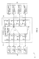
- Fig. 2 is a simplified block diagram illustration of a preferred implementation of one of the OSAs 45 and 50 in the optical communication network 10 of Fig. 1.
- the description below refers to one of the OSAs 50 shown in Fig. 1 to be operatively associated with one of the plurality of remote node servers 25 that is indicated as remote node server-2.
- the OSA 50 that is shown in Fig. 1 to be operatively associated with the remote node server-2 is referred to in Fig. 2 as optical switching apparatus 100.
- the present invention is not limited by referring to the optical switching apparatus 100 and its association with the remote node server-2 because, as mentioned above, all the OSAs 45 and 50 are similar in structure and functionality.
- the remote node server-2 may be, for example a CO (not shown) located in a city (not shown) away from the CO 15, and both the remote node server-2 and the CO 15 may form part of a metropolitan area network (MAN) (not shown).
- the optical switching apparatus 100 in the CO 15 may then interface to the MAN and enable the CO 15 to communicate with the remote node server-2 via the MAN.
- the optical switching apparatus 100 preferably switches and routes optical signal samples communicated in a direction upstream and in a direction downstream.
- upstream is used throughout the specification and claims to refer to a direction of communication towards one of the plurality of node servers 25, such as towards the remote node server-2.
- downstream is used throughout the specification and claims to refer to a direction of communication towards one of the plurality of end nodes 20.
- upstream communication may include transmission of optical information from some of the end nodes 20 to the remote node server-2 as well as transmission of optical information from remote node servers 25 other than the remote node server-2 to the remote node server-2 via the switch 30.
- Downstream communication may include, for example, transmission of optical information from the remote node server-2 to some of the end nodes 20 as well as transmission of optical information from one of the end nodes 20 to other end nodes 20 via the switch 30.
- the optical signal samples switched and routed by the optical switching apparatus 100 may be either analog optical signals or digital optical signals that represent optical information. If the optical signal samples are digital optical signals, each optical signal sample typically includes a bit. Preferably, the optical signal samples are coded in a return-to-zero (RZ) line code with adjacent optical signal samples being spaced by time spacing T. However, it is appreciated that the optical signal samples may alternatively be coded in other line codes as described below.
- RZ return-to-zero
- the optical switching apparatus 100 may preferably receive n series of upstream optical signal samples, where n is an integer greater than one.
- Each series of upstream optical signal samples in the n series of upstream optical signal samples is preferably carried over a channel wavelength ⁇ i at a data rate DR i , where i is an index running from 1 to n. It is appreciated that each series of upstream optical signal samples in the n series of upstream optical signal samples may carry optical signal samples in an optical time-division multiplexed form.
- the optical switching apparatus 100 may preferably include L ports 102 and the n series of upstream optical signal samples are preferably received at the optical switching apparatus 100 via n of the L ports 102.
- the n series of upstream optical signal samples received via the n ports 102 are provided to an optical converter unit 105 that is preferably comprised in the optical switching apparatus 100.
- the optical converter unit 105 may preferably operate as an upstream optical converter unit for upstream communication as well as a downstream optical converter unit for downstream communication.
- the optical converter unit 105 is preferably operative to convert the n series of upstream optical signal samples into a combined series of upstream optical signal samples having the upstream optical signal samples carried over a channel wavelength ⁇ D at a combined data rate DR c which is greater than any separate DR i .
- the channel wavelength ⁇ D is preferably a channel wavelength that is useful for carrying optical signal samples to a destination route.
- the destination route which preferably guides the optical signal samples, for example, to the remote node server-2, may include one of the following communication media: a fiber optic cable capable of carrying optical signal samples at the combined data rate DR c ; a wireless communication route; a waveguide other than a fiber optic cable; a transmission line; an interface to an optical transceiver; and an interface to an optical communication system operating at the combined data rate DR c .
- the term "transceiver" is used throughout the specification and claims to include a transmitter and a receiver, preferably combined together.
- the optical converter unit 105 provides the combined series of upstream optical signal samples to a router 110 that is also preferably comprised in the optical switching apparatus 100.
- the router 110 is preferably operative to route the combined series of upstream optical signal samples to the destination route at the combined data rate DR c .
- the optical switching apparatus 100 may also include a controller 115 that is operatively associated with the optical converter unit 105 and is operative to determine the number of series n converted by the optical converter unit 105 and combined in the combined series of upstream optical signal samples. It is appreciated that the controller 115 may be also operative to select the channel wavelength ⁇ D , preferably from ⁇ 1 ,..., ⁇ n and optionally, in response to an instruction received, for example, from the remote node server-2.
- the optical converter unit 105 may preferably include a wavelength converter unit 120, a combiner 125 and a motion controller 130.
- the wavelength converter unit 120 preferably includes a plurality of wavelength converters 135.
- conversion of the n series of upstream optical signal samples into the combined series of upstream optical signal samples having the upstream optical signal samples carried over a channel wavelength ⁇ D at a combined data rate DR c is performed by the optical converter unit 105 as follows: the plurality of wavelength converters 135, that receive the n series of upstream optical signal samples provided via the n ports, preferably convert any channel wavelength ⁇ i that differs from ⁇ D to ⁇ D thereby forming a group of n series of upstream optical signal samples having the upstream optical signal samples carried over ⁇ D .
- the wavelength converter unit 120 provides the group of n series of upstream optical signal samples having the upstream optical signal samples carried over ⁇ D to the combiner 125 which is operative to combine the n series of upstream optical signal samples in the group so as to provide the combined series of upstream optical signal samples having the upstream optical signal samples carried over ⁇ D at the combined data rate DR c that is provided by the router 110 to the destination route.
- the motion controller 130 is preferably operative to control motion of the wavelength converter unit 120 and the combiner 125.
- Motion backward or forward of the wavelength converter unit 120 and the combiner 125 is preferably provided by micro-positioners (M-Ps) 140 and 145 that are preferably coupled to the wavelength converter unit 120 and combiner 125 respectively.
- the micro-positioners 140 and 145 are preferably operative to move the wavelength converter unit 120 and the combiner 125 in synchronization under control of the motion controller 130.
- controller 115 may also have the functionality of the motion controller 130 in which case the motion controller 130 is optional.
- each of the plurality of wavelength converters 135 may be associated with an ON/OFF switch, such as a mechanical switch (M-S) 150.
- M-S 150 When an M-S 150 is in the "ON” state, the M-S 150 passes optical signal samples to a wavelength converter unit 135 associated therewith. When the M-S 150 is in the "OFF” state, passage of optical signal samples to the wavelength converter 135 that is associated with the M-S 150 is blocked.
- the motion controller 130 is also operative to control operation of the M-Ss 150.
- the router 110 may preferably be coupled to a micro-positioner 155 that is operative to move the router 110 backward or forward.
- the motion controller 130 is preferably operatively associated with the micro-positioner 155 and is operative to control the micro-positioner 155.
- the router 110 is preferably moved in synchronization with the wavelength converter unit 120 and the combiner 125.
- the wavelength converter unit 120, the combiner 125 and the router 110 and operation of the M-Ss 150 may be required in various applications.
- the wavelength converter unit 120 and the combiner 125 may be moved backward or forward in order to receive series of optical signal samples from different end nodes 20.
- the optical switching apparatus 100 may be required to combine different numbers of series of optical signal samples depending on the capacity of the remote node server 25 that is associated with the optical switching apparatus 100.
- selection of the number n of series of optical signal samples to be combined by the optical switching apparatus 100 may be performed by programming the motion controller 130 to provide a suitable combination of M-Ss 150 in ON states that allow passage of series of upstream optical signal samples and M-Ss 150 in OFF states that block passage of series of upstream optical signal samples.
- the programming of the motion controller 130 may be performed, for example, in response to an indication received from the remote node server 25 that is associated with the optical switching apparatus 100.
- the combiner 125 may preferably include a clock-recovery unit 160, an optical delay mechanism 165 and a multiplexer/demultiplexer (MUX/DEMUX) 170.
- the clock-recovery unit 160 is preferably operative to receive the group of n series of upstream optical signal samples having the upstream optical signal samples carried over ⁇ D from the wavelength converters 135 and to recover a clock signal CLK i for each series of optical signal samples in the group.
- the clock-recovery unit 160 is operative to perform all-optical clock recovery for each of the series in the group.
- An example of a system that performs all-optical clock recovery is a system described in the above-mentioned article of Wang et al that performs all-optical clock recovery based on AM mode-locking of a fiber ring laser.
- Another example of a system that performs all-optical clock recovery is a system described in the above-mentioned article of Kawanishi et al that performs all-optical clock recovery based on a phase-locked-loop (PLL).
- PLL phase-locked-loop
- the clock-recovery unit 160 may include more than one of the systems of Wang et al or Kawanishi et al in order to recover the clock signals of all the series in the group.
- the optical delay mechanism 165 which is preferably operatively associated with the clock-recovery unit 160, may generate time delays of at least a fraction of the time spacing T between every two series of upstream optical signal samples in the group so as to create a group of n sequentially delayed series of upstream optical signal samples in which a delay between every two series of upstream optical signal samples is at least a fraction of T.
- the optical delay mechanism 165 may include, for example, a plurality of delay generators which delay optical signals without using optical-to-electronic and electronic-to-optical conversions as described in copending US patent application No. 09/389,345 filed on September 3, 1999.
- the optical delay mechanism 165 may use, for example, a signal phase discriminator (not shown) to sense phase variations among the series of optical signal samples, and the controller 115, or a controller comprised in the optical delay mechanism 165 (not shown), may select, based on sensed phase variations among the series of optical signal samples, those of the plurality of delay generators to be used by the optical delay mechanism 165 so as to ultimately provide the time delays, for example, in the form of the following series of time delays: 0, ⁇ T, 2 ⁇ T, 3 ⁇ T,..., (n-1) ⁇ T, where ⁇ T is the fraction of T.
- the optical delay mechanism 165 may generate the time delays using, for example, a delay line setup as described in the above-mentioned article of Klovekorn et al or arrangements that use a nonlinear optical loop mirror (NOLM) as described in the above-mentioned articles of Hall et al.
- NOLM nonlinear optical loop mirror
- the optical delay mechanism 165 preferably provides the group of n sequentially delayed series of upstream optical signal samples to the MUX/DEMUX 170.
- the MUX/DEMUX 170 may include, for example, a passive star coupler (not shown) that multiplexes the n sequentially delayed series of upstream optical signal samples in the group so as to provide the combined series of upstream optical signal samples which is provided to the router 110 and fed by the router 110 to the destination route.
- the combined series of upstream optical signal samples may be amplified by an optical amplifier 175, such as an Erbium-doped-fiber-amplifier (EDFA) for wavelengths around 1550 nanometer (nm), before feeding to the destination route.
- the optical amplifier 175 may be comprised in the optical switching apparatus 100 or associated therewith. It is appreciated that optical amplifiers (not shown) may also be operatively associated with the wavelength converters 135 and the clock-recovery unit 160 for amplifying signals emanating therefrom.
- ⁇ T in order to prevent overlapping of the optical signal samples multiplexed by the MUX/DEMUX 170, ⁇ T must be less than T minus WD, where WD is a characteristic duration of an optical signal sample in the n series of upstream optical signal samples. Additionally or alternatively, the highest delay between any two series of upstream optical signal samples in the group of n sequentially delayed series of upstream optical signal samples should not exceed T minus WD.
- the ratio T/WD which is preferably computed by the controller 115, determines the number n of series of upstream optical signal samples that can be combined in the combined series of upstream optical samples. The controller 115 preferably determines n to be the highest integer that satisfies the inequality n ⁇ T/WD.
- the controller 115 may select delay generators or delay line setups to provide a series of time delays growing by a constant step, such as the series of time delays 0, ⁇ T, 2 ⁇ T, 3 ⁇ T,...,(n-1) ⁇ T mentioned above.
- the MUX/DEMUX 170 may include a synchronous time-division multiplexer which is operative to synchronously time-division multiplex the n sequentially delayed series of upstream optical signal samples in the group so as to provide the combined series of upstream optical signal samples.
- the controller 115 may select delay generators or delay line setups to provide a series of variably growing time delays.
- the MUX/DEMUX 170 may include an asynchronous time-division multiplexer which is operative to asynchronously time-division multiplex the n sequentially delayed series of upstream optical signal samples in the group so as to provide the combined series of upstream optical signal samples.
- the asynchronous time-division multiplexer determines the delay between every two series of upstream optical signal samples and creates the group of n sequentially delayed series of upstream optical signal samples.
- a star coupler (not shown) may be used as a combination of the multiplexer portion of the MUX/DEMUX 170, the router 110 and the destination route since a fused fiber portion of the star coupler that is coupled to n ports of the star coupler may form part of all of the following: the multiplexer portion of the MUX/DEMMUX 170, the router 110 and the destination route.
- the destination route may be operatively associated with an add/drop multiplexer (ADM) 180.
- the ADM 180 is preferably operative to multiplex by wavelength division multiplexing (WDM) the upstream optical signal samples in the combined series of upstream optical signal samples having the upstream optical signal samples carried over ⁇ D at the combined data rate DR c with optical signal samples multiplexed by WDM that may be provided to the ADM 180, for example, from OSAs 50 other than the optical switching apparatus 100 or from other information sources (not shown) external to the CO 15.
- WDM wavelength division multiplexing
- the ADM 180 may preferably be separated from the optical switching apparatus 100 or alternatively embodied in the router 110 and associated with the destination route.
- WDM wavelength division multiplexing
- WDM wavelength division multiplexing of optical signals carried over a plurality of channel wavelengths within any suitable wavelength range.
- WDM is used throughout the specification and claims to include wavelength division multiplexing of optical signals carried over two channel wavelengths, wavelength division multiplexing of optical signals carried over more than two and up to tens of channel wavelengths for which the term “dense WDM” (DWDM) is typically used, and wavelength division multiplexing of optical signals carried over tens to hundreds of channel wavelengths for which the term “optical frequency division multiplexing” (OFDM) is typically used.
- DWDM dense WDM
- OFDM optical frequency division multiplexing
- Channel wavelengths typically used for WDM include wavelengths in bands of the order of tens nm around each of the following wavelengths: 780 nm; 980 nm; 1310 nm; 1480 nm; 1550 nm; and 1620 nm. It is appreciated that optical signals carried over channel wavelengths in different wavelength bands may also be multiplexed by WDM.
- the ADM 180 may preferably drop a series of downstream optical signal samples carried over a channel wavelength ⁇ T at a data rate DR T that is communicated by the remote node server-2 to the optical switching apparatus 100. It is appreciated that the series of downstream optical signal samples may be carried over the channel wavelength ⁇ T in a time-division multiplexed form.
- the optical switching apparatus 100 may receive the series of downstream optical signal samples at the router 110 after amplification by the optical amplifier 175.
- the router 110 preferably provides the series of downstream optical signal samples to the optical converter unit 105 which is preferably operative to convert the series of downstream optical signal samples into nn series of downstream optical signal samples having the downstream optical signal samples carried over channel wavelengths ⁇ 1 ,..., ⁇ nn-1 , ⁇ T at data rates DRT 1 ,...,DRT nn respectively, where nn is an integer greater than one, ⁇ 1 # ⁇ T ,..., ⁇ nn-1 # ⁇ T and each of DRT 1 ,..., DRT nn is less than DR T .
- the optical converter unit 105 provides the nn series of downstream optical signal samples having the downstream optical signal samples carried over the channel wavelengths ⁇ 1 ,..., ⁇ nn-1 , ⁇ T at the data rates DRT 1 ,...,DRT nn to the switching fabrics 55 which functions, for this purpose, as a router that routes the nn series of downstream optical signal samples to nn appropriate destinations, such as nn of the L end nodes 20.
- the number nn of series of downstream optical signal samples may preferably be determined by the controller 115, and selected, for example, by the controller 115 instructing the motion controller 130 to provide a suitable combination of M-Ss 150 in ON states and M-Ss 150 in OFF states.
- the controller 115 may additionally be operative to select the channel wavelengths ⁇ 1 ,..., ⁇ nn-1 prior to conversion of the series of downstream optical signal samples into the nn series of downstream optical signal samples.
- the MUX/DEMUX 170 preferably performs optical time-division demultiplexing of the series of downstream optical signal samples so as to provide a group of nn series of downstream optical signal samples, each having the optical signal samples carried over ⁇ T at a corresponding one of the data rates DRT 1 ,...,DRT nn .
- the group of nn series of optical signal samples is then provided to the wavelength converter unit 120.
- the wavelength converters 135 preferably convert ⁇ T of all except one of the series of downstream optical signal samples in the group into the channel wavelengths ⁇ 1 ,..., ⁇ nn-1 so as to provide the nn series of downstream optical signal samples having the downstream optical signal samples carried over the channel wavelengths ⁇ 1 ,..., ⁇ nn-1 , ⁇ T at the respective data rates DRT 1 ,...,DRT nn . Then, the wavelength converters 135 provide the nn series of downstream optical signal samples having the downstream optical signal samples carried over the channel wavelengths ⁇ 1 ,..., ⁇ nn-1 , ⁇ T at the data rates DRT 1 ,...,DRT nn to the switching fabrics 55.
- the demultiplexer portion of the MUX/DEMUX 170 may include a setup as described, for example, in the article of Ellis et al with different switching windows for each series of downstream optical signal samples in the group.
- Alternative setups that may be suitable for the demultiplexer portion of the MUX/DEMUX 170 are described in the above mentioned articles of Eiselt et al and Patrick et al.
- the MUX/DEMUX 170 includes a synchronous time-division demultiplexer which performs synchronous optical time-division demultiplexing of the series of downstream optical signal samples
- the resulting data rates DRT 1 ,...,DRT nn of the nn series of downstream optical signal samples are equal.
- the MUX/DEMUX 170 includes an asynchronous time-division demultiplexer which performs asynchronous optical time-division demultiplexing of the series of downstream optical signal samples, at least some of the resulting data rates DRT 1 ,...,DRT nn of the nn series of downstream optical signal samples are not equal.
- each of the data rates DR 1 , DR 2 , DR 3 , and DR 4 may be, for example, equal to 2.5Gbit/sec.
- the optical signal samples in each of the four series of upstream optical signal samples are preferably multiplexed by OTDM, and each of the four series of upstream optical signal samples is preferably coded in an RZ line code with adjacent optical signal samples being spaced by a time spacing T.
- the controller 115 preferably selects the channel wavelength ⁇ D to be, for example, ⁇ 1 . Then, the wavelength converters 135 preferably convert each of the channel wavelengths ⁇ 2 , ⁇ 3 , ⁇ 4 into ⁇ 1 thereby forming a group of four series of upstream optical signal samples having the upstream optical signal samples carried over ⁇ 1 .
- the group of four series of upstream optical signal samples having the upstream optical signal samples carried over ⁇ 1 is provided to the combiner 125.
- the clock signals for the four series of upstream optical signal samples are preferably recovered and time delays of T/4, T/2 and 3T/4 are preferably respectively generated among the series of upstream optical signal samples in the group so as to form a group of four sequentially delayed series of upstream optical signals having the upstream optical signal samples carried over ⁇ 1 .
- the four sequentially delayed series of upstream optical signal samples in the group are preferably time-division multiplexed, in this case synchronously, thereby providing a combined series of upstream optical signal samples which carries optical signal samples over the channel wavelength ⁇ 1 at a combined data rate of 10Gbit/sec.
- the combined series of upstream optical signal samples may be routed via the destination route, for example, to the remote node server-2.
- the operation of the optical switching apparatus 100 resulted in a speedup of optical communication in the upstream by a factor of four.
- Such speedup may be required, for example, in a case where the end nodes 20 and the remote node servers 25 communicate with the CO 15 at different data rates. This may occur, for example, when the remote node servers 25 and the end nodes 20 include different generations of communication hardware.
- the series of downstream optical signal samples is preferably provided to the combiner 125.
- the four series of downstream optical signal samples having the downstream optical signal samples carried over the channel wavelengths ⁇ 1 , ⁇ 2 , ⁇ 3 and ⁇ 4 at the data rates DRT 1 , DRT 2 , DRT 3 and DRT 4 may then be provided to the switching fabrics 55.
- the switching fabrics 55 may route the four series of downstream optical signal samples having the downstream optical signal samples carried over the channel wavelengths ⁇ 1 , ⁇ 2 , ⁇ 3 and ⁇ 4 at the data rates DRT 1 , DRT 2 , DRT 3 and DRT 4 to the four end nodes 20 respectively. It is thus appreciated that the operation of the optical switching apparatus 100 resulted in a slow-down of optical communication in the downstream by a factor of four.
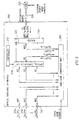
- Fig. 3 is a simplified block diagram illustration of a preferred implementation of an optical switching apparatus 200 in the optical communication network 10 of Fig. 1.
- the optical switching apparatus 200 may preferably replace the optical switching apparatus 100 of Fig. 2 in applications in which optical signal samples communicated to and from the optical switching apparatus 200 are coded in a line code other than an RZ line code.
- the line code other than an RZ line code may be, for example, a non-return-to zero (NRZ) line code.
- the optical switching apparatus 200 may preferably receive n series of NRZ coded upstream optical signal samples via ports 202, where n is an integer.
- Each of the n series of NRZ coded upstream optical signal samples is preferably carried over a channel wavelength ⁇ i at a data rate DR i , where i is an index running from 1 to n.
- the n series of NRZ coded upstream optical signal samples are provided to a line code converter unit 205 that is operatively associated with the optical switching apparatus 200 and may also be comprised in the optical switching apparatus 200.
- the line code converter unit 205 is preferably operative to convert the n series of NRZ coded upstream optical signal samples into n series of RZ coded upstream optical signal samples.
- the line converter unit 205 may include a conventional transceiver of RZ coded optical signal samples (not shown) that is operatively associated with a conventional transceiver of NRZ coded optical signal samples (not shown).
- NRZ coded optical signal samples For conversion of optical signal samples from an NRZ line code to an RZ line code, NRZ coded optical signal samples, that are received and decoded at the receiver portion of the transceiver of NRZ coded optical signal samples, are encoded in an RZ line code and transmitted by the transmitter portion of the transceiver of RZ coded optical signal samples.
- RZ coded optical signal samples For conversion of optical signal samples from an RZ line code to an NRZ line code, RZ coded optical signal samples, that are received and decoded at the receiver portion of the transceiver of RZ coded optical signal samples, are encoded in an NRZ line code and transmitted by the transmitter portion of the transceiver of NRZ coded optical signal samples.
- the line code converter unit 205 may receive indications of the type of the line code other than an RZ line code to be used from the remote node server-2 of Fig. 1 and apply transceivers of optical signal samples coded in corresponding line codes as necessary.
- the n series of RZ coded upstream optical signal samples are provided to an optical converter unit 210 that may be similar in structure and functionality to the optical converter unit 105 of Fig. 2.
- the n series of RZ coded upstream optical signal samples are converted into a combined series of RZ coded upstream optical signal samples having the upstream optical signal samples carried over a channel wavelength ⁇ D at a combined data rate DR c in a manner as mentioned above with reference to Fig. 2.
- the optical converter unit 210 may be controlled by a controller 215 that may be similar in structure and functionality to the controller 115 of Fig. 2.
- the optical converter unit 210 provides the combined series of RZ coded upstream optical signal samples back to the line code converter unit 205 which preferably converts the combined series of RZ coded upstream optical signal samples into a combined series of NRZ coded upstream optical signal samples.
- the line code converter unit 205 preferably provides the combined series of NRZ coded upstream optical signal samples to a router 220 that may be similar in structure and functionality to the router 110 of Fig. 2 and may similarly be moved by a micro-positioner (M-P) 225 that may be controlled via the optical converter unit 210.
- M-P micro-positioner
- the router 220 may preferably route the combined series of NRZ coded upstream optical signal samples to a destination route which preferably provides the combined series of NRZ coded upstream optical signal samples to an ADM 235, preferably after amplification by an optical amplifier 230.
- the ADM 235 may preferably be similar in structure and functionality to the ADM 180 of Fig. 2.
- the ADM 235 is preferably operative to multiplex by WDM the NRZ coded upstream optical signal samples in the combined series of NRZ coded upstream optical signal samples with optical signal samples multiplexed by WDM that may be provided to the ADM 235, for example, from information sources (not shown) external to the optical switching apparatus 200.
- the output of the ADM 235 is preferably provided to the remote node server-2 of Fig. 1. It is appreciated that the ADM 235 is preferably separated from the optical switching apparatus 200 or alternatively embodied in the router 220 and associated with the destination route.
- a series of NRZ coded downstream optical signal samples carried over a channel wavelength ⁇ T at a data rate DR T that is transmitted from the remote node server-2 of Fig. 1 is preferably dropped by the ADM 235, amplified by the optical amplifier 230, and provided to the line code converter unit 205 via the router 220.
- the line code converter unit 205 preferably converts the series of NRZ coded downstream optical signal samples into a series of RZ coded downstream optical signal samples that is preferably separated, in the optical converter unit 210, so as to provide nn series of RZ coded downstream optical signal samples having the downstream optical signal samples carried over channel wavelengths ⁇ 1 ,..., ⁇ nn-1 , ⁇ T at data rates DRT 1 ,...,DRT nn in a manner as mentioned above with reference to Fig. 2.
- the nn series of RZ coded downstream optical signal samples are then provided to the line code converter unit 205 which preferably converts the nn series of RZ coded downstream optical signal samples into nn series of NRZ coded downstream optical signal samples.
- the nn series of NRZ coded downstream optical signal samples are then preferably routed, for example, to the switching fabrics 55 of Fig. 1.
- Fig. 4 is a simplified block diagram illustration of a preferred implementation of an optical switching apparatus 300 in the optical communication network 10 of Fig. 1.
- the optical switching apparatus 300 may preferably replace the optical switching apparatus 100 of Fig. 2 in applications in which optical signal samples communicated to and from the optical switching apparatus 300 are provided in a wavelength division multiplexed form.
- the optical switching apparatus 300 may preferably receive at ports 305 a plurality of series of upstream optical signal samples.
- the plurality of series of upstream optical signal samples are preferably received from the switching fabrics 55 of Fig. 1 via separate waveguides, such as via m separate fiber optic cables FOC 1 , FOC 2 ,...,FOC m , where m is an integer greater than or equal to 1.
- the fiber optic cables FOC 1 , FOC 2 ,...,FOC m carry groups of k 1 ,....,k m series of upstream optical signal samples respectively, preferably in a wavelength division multiplexed form over channel wavelengths ⁇ ii,jj ⁇ at data rates ⁇ DR ii,jj ⁇ respectively, where k 1 ,....,k m are integers greater than one, ii is an index running from 1 to m, and jj is an index running from 1 to k j where j is an index running from 1 to m.
- the plurality of series of optical signal samples received at the ports 305 are provided to a multiplexing/demultiplexing unit 310 in the optical switching apparatus 300 that may preferably be a WDM multiplexing/demultiplexing unit.
- the multiplexing/demultiplexing unit 310 may include one ADM 315 or a plurality of ADMs 315.
- the multiplexing/demultiplexing unit 310 may include one wavelength division multiplexer/demultiplexer such as a star coupler/decoupler (not shown) or a plurality of wavelength division multiplexers/demultiplexers (not shown).
- the multiplexing/demultiplexing unit 310 is preferably operatively associated with a controller 320 and a router 325 that are preferably comprised in the optical switching apparatus 300.
- the controller 320 and the router 325 are also preferably operatively associated with an optical converter unit 330 that may also be comprised in the optical switching apparatus 300 and may be similar in structure and functionality to the optical converter unit 105 of Fig. 2.
- the optical converter unit 330 is also preferably operatively associated with a router 335 and a micro-positioner 340 associated with router 335.
- the router 335 and the micro-positioner 340 may be comprised in the optical switching apparatus 300 and may be similar in structure and functionality to the router 110 and the micro-positioner 155 of Fig. 2 respectively.
- the controller 320 may be operative to control operation of the ADMs 315 in the multiplexing/demultiplexing unit 310, the router 325 and the optical converter unit 330. It is appreciated that the controller 320 may receive inputs from the remote node server-2 of Fig. 1 and control operation of the ADMs 315, the router 325 and the optical converter unit 330 based, for example, on the inputs received from the remote node server-2 of Fig. 1. Alternatively, the controller may be pre-programmed or programmed to operate independently of the remote node server-2.
- controller 320 may also have the functionality of a controller (not shown) in the optical converter unit 330 that corresponds to the controller 115 of Fig. 2 in which case the controller in the optical converter unit 330 is optional.
- the controller 320 is operative to select n series of upstream optical signal samples from the groups of k 1 ,....,k m series of upstream optical signal samples.
- the controller 320 may select the n series of upstream optical signal samples, for example, from a group of series of upstream optical signal samples carried over one of the fiber optic cables FOC 1 , FOC 2 ,...,FOC m or from a plurality of groups of series of upstream optical signal samples carried over a plurality of the fiber optic cables FOC 1 , FOC 2 ,...,FOC m respectively.
- the number n of series of upstream optical signal samples may be selected, for example, in accordance with a capacity of the remote node server-2.
- the ADMs 315 drop the n series of upstream optical signal samples selected by the controller 320 from those of the m separate fiber optic cables FOC 1 , FOC 2 ,...,FOC m that carry the selected n series of upstream optical signal samples.
- the n series of upstream optical signal samples may be separated by demultiplexing at least some of the k 1 ,....,k m series of upstream optical signal samples in the groups of k 1 ,....,k m series of upstream optical signal samples so as to provide LK demultiplexed series of upstream optical signal samples, where LK is an integer greater than one and less than or equal to k 1 +...+k m , and selecting each of the n series of upstream optical signal samples from the LK demultiplexed series of upstream optical signal samples.
- the n series of upstream optical signal samples dropped or separated by the multiplexing/demultiplexing unit 310 are preferably provided to the router 325 which preferably arranges and routes the n series of upstream optical signal samples to n ports (not shown) of the optical converter unit 330.
- the optical converter unit 330 and the router 335 preferably operate in a manner as mentioned above with reference to Fig. 2 to combine the n series of upstream optical signal samples, using OTDM, so as to provide, at the output of the router 335, a combined series of upstream optical signal samples having the upstream optical signal samples carried over a channel wavelength ⁇ D at a combined data rate DR c .
- the router 335 preferably provides the combined series of upstream optical signal samples to an ADM 350 that may be comprised in the optical switching apparatus 300 or external to the optical switching apparatus 300 and operatively associated therewith.
- series of upstream optical signal samples that are not provided to the router 325 are provided, for example over at least some of the m separate fiber optic cables FOC 1 , FOC 2 ,...,FOC m , to a selector 345 that may be comprised in the optical switching apparatus 300 and controlled by the controller 320.
- the selector 345 may include, for example, a mechanical switch (not shown) that selects one of the fiber optic cables FOC 1 , FOC 2 ,...,FOC m under control of the controller 320 and outputs series of upstream optical signal samples that are carried over a selected fiber optic cable to the ADM 350, and series of upstream optical signal samples that are carried over non-selected fiber optic cables to a separate optical switching apparatus 400 (not shown) that may be similar in structure and functionality to the optical switching apparatus 300.
- the optical switching apparatus 400 may operate together with the optical switching apparatus 300 in a cascaded form as described below.
- the ADM 350 preferably employs WDM to add the combined series of upstream optical signal samples having the upstream optical signal samples carried over ⁇ D to series of upstream optical signal samples that are carried over the fiber optic cable selected by the selector 345 in a wavelength division multiplexed form thereby generating a combined series of upstream optical signal samples, combined by both OTDM and WDM. Then, the ADM 350 transmits the combined series of upstream optical signal samples, combined by both OTDM and WDM, to the remote node server-2 of Fig. 1 via a destination fiber optic cable 355, preferably after amplification by an optical amplifier 360.
- a group of series of downstream optical signal samples multiplexed by WDM that is transmitted from the remote node server-2 of Fig. 1 is preferably received at the ADM 350 in the optical switching apparatus 300. It is appreciated that each series of downstream optical signal samples in the group may carry the optical signal samples at a data rate DR T .
- the ADM 350 separates a series of downstream optical signal samples carried over a channel wavelength ⁇ T at the data rate DR T from the group and provides the separated series of downstream optical signal samples to the router 335.
- the ADM 350 also preferably provides the rest of the series of downstream optical signal samples in the group, that are carried over channel wavelengths other than ⁇ T , to the selector 345.
- the selector 345 preferably provides the series of downstream optical signal samples received thereat to at least one of the ADMs 315 selected by the controller 320, for example the ADM 315 that is operatively associated with the fiber optic cable FOC 2 .
- the router 335 preferably provides the series of downstream optical signal samples carried over the channel wavelength ⁇ T at the data rate DR T to the optical converter unit 330.
- the optical converter unit 330 preferably separates, in a manner as mentioned above with reference to Fig.
- the series of downstream optical signal samples carried over the channel wavelength ⁇ T at the data rate DR T so as to provide nn series of downstream optical signal samples having the downstream optical signal samples carried over channel wavelengths ⁇ 1 ,..., ⁇ nn-1 , ⁇ T at data rates DRT 1 ,...,DRT nn .
- the nn series of downstream optical signal samples are preferably provided to nn ADMs 315 including, for example, the ADM 315 that is operatively associated with the fiber optic cable FOC 2 .
- the ADM 315 that is operatively associated with the fiber optic cable FOC 2 preferably adds, using WDM, a corresponding one of the nn series of downstream optical signal samples to the series of downstream optical signal samples provided thereto by the selector 345 and routes outputted series of upstream optical signal samples multiplexed by WDM to the fiber optic cable FOC 2 .
- the other nn-1 ADMs 315 may, for example, route the nn-1 corresponding series of downstream optical signal samples to the fiber optic cables FOC 1 , FOC 3 ,..., FOC nn respectively.
- series of downstream optical signal samples multiplexed by WDM may be separated and recombined to provide, for example, various distributions in which the same fiber optic cable may carry series of downstream optical signal samples at different data rates.
- the optical switching apparatus 300 may receive eight series of upstream optical signal samples for routing to the node server-2.
- the remote node server-2 may include, for example, equipment that can communicate with the optical switching apparatus 300 at a higher data rate over each channel wavelength, such as at 10Gbit/sec, but can allot less channel wavelengths for communication with the optical switching apparatus 300, for example five channel wavelengths.
- the other four series of upstream optical signal samples carried over ⁇ 5 , ⁇ 6 , ⁇ 7 and ⁇ 8 may preferably be provided unchanged, via the multiplexing/demultiplexing unit 310 and the selector 345, to the ADM 350.
- the ADM 350 may use WDM to add the combined series of upstream optical signal samples having the optical signal samples carried over ⁇ 1 to the four series of upstream optical signal samples carried over ⁇ 5 , ⁇ 6 , ⁇ 7 and ⁇ 8 so as to provide five series of upstream optical signal samples multiplexed by WDM and carried over ⁇ 1 , ⁇ 5 , ⁇ 6 , ⁇ 7 and ⁇ 8 , where the series of upstream optical signal samples carried over ⁇ 1 is carried at 10Gbit/sec, and each of the other four series of upstream optical signal samples is carried at 2.5Gbit/sec.
- the five series of upstream optical signal samples are preferably routed to the remote node server-2.
- optical switching apparatus 300 may perform alternative combinations of the eight series of upstream optical signal samples received thereat depending, for example, on criteria and constraints received from the remote node server-2 or determined by the controller 320.
- One type of criteria and constraints that may be determined by the controller 320 may include, for example, occurrence of interference effects among different channel wavelengths. Referring, for example, to a case where interference effects occur between the channel wavelengths ⁇ 2 and ⁇ 6 , conventional WDM of the eight channel wavelengths ⁇ 1 ,..., ⁇ 8 in such a case is not desirable. However, when the optical switching apparatus 300 is used to provide the five series of upstream optical signal samples multiplexed by WDM and carried over ⁇ 1 , ⁇ 5 , ⁇ 6 , ⁇ 7 and ⁇ 8 , such interference effects are avoided.
- the optical switching apparatus 300 also receives eight series of upstream optical signal samples for routing to the node server-2, but the eight series of upstream optical signal samples are provided at different data rates.
- the combined series of upstream optical signal samples may then be provided to the ADM 350.
- the series of upstream optical signal samples carried over ⁇ 1 , ⁇ 3 , ⁇ 5 and ⁇ 7 may preferably be provided unchanged, via the multiplexing/demultiplexing unit 310 and the selector 345, to the ADM 350.
- the ADM 350 preferably combines the series of upstream optical signal samples carried over ⁇ 1 , ⁇ 3 ⁇ 5 and ⁇ 7 with the combined series of upstream optical signal samples having the optical signal samples carried over ⁇ 2 by using WDM so as to transmit to the remote node server-2 five series of upstream optical signal samples having the upstream optical signal samples carried over ⁇ 1 , ⁇ 2 , ⁇ 3 , ⁇ 5 and ⁇ 7 at similar data rates of 10Gbit/sec.
- series of upstream optical signal samples may be combined in a plurality of combination stages by employing the optical switching apparatus 300 in a cascaded form together with the optical switching apparatus 400 or a plurality thereof.
- the controller 320 or a corresponding controller (not shown) in one of the plurality of optical switching apparatus 400 may determine the series of upstream optical signal samples to be combined and whether to perform combination by utilizing OTDM and/or WDM.
- series of downstream optical signals that are transmitted in a direction downstream are separated by utilizing WDM and/or OTDM in accordance with selections made by the controller 320 and under control of the controller 320.
- a fourth example refers to a case where at least one of the fiber optic cables FOC 1 , FOC 2 ,...,FOC m , such as FOC 1 , carries upstream optical signal samples that are obtained by a spread spectrum technique such as an optical code division multiple access (OCDMA) technique.
- a spread spectrum technique such as an optical code division multiple access (OCDMA) technique.
- the rest of the fiber optic cables FOC 2 ,...,FOC m may preferably carry upstream optical signal samples that are obtained from NCC sources and include at least one of the following: upstream optical signal samples that are separately obtained from NS out of the NCC sources by the spread spectrum technique; and n series of upstream optical signal samples that are separately obtained from n out of the NCC sources and are carried over n discrete channel wavelengths, where each of NCC, n and NS is an integer greater than one.
- upstream optical signal samples that can be switched to the remote node server-2 may include either a combination of upstream optical signal samples that are obtained by a spread spectrum technique and upstream optical signal samples that are separately obtained from n out of the NCC sources and are carried over n discrete channel wavelengths, or only upstream optical signal samples that are obtained by a spread spectrum technique.
- the upstream optical signal samples obtained by the spread spectrum technique and carried over FOC 1 are provided at a data rate DRS.
- the upstream optical signal samples obtained from the NS sources are provided at data rates DRSS j , and each series of upstream optical signal samples in the n series of upstream optical signal samples is carried over a discrete channel wavelength ⁇ i at a data rate DR i , where i is an index running from 1 to n, and j is an index running from 1 to NS.
- DRS, each of DRSS j , and each of DR i may, for example, be different.
- DRS and similarly each of DRSS j , result from the spreading performed in the OCDMA technique of lower data rate optical signal samples.
- At least one of the ADMs 315 in the multiplexing/demultiplexing unit 310 such as the ADM 315 that is operatively associated with the fiber optic cable FOC 1 , preferably includes a grouped ADM (GADM).
- the GADM is preferably operative to drop optical signal samples that occupy a wavelength band, and also, when combined with a conventional ADM, optical signal samples that are carried over discrete channel wavelengths.
- the GADM may drop, for example, the upstream optical signal samples spread between ⁇ 1 and ⁇ 3 and centered at ⁇ 2 , and the upstream optical signal samples carried over ⁇ 4 .
- the two series of upstream optical signal samples carried by FOC 2 over the discrete channel wavelengths ⁇ 6 and ⁇ 7 may also be dropped by another ADM 315.
- NS GADMs are typically required to respectively drop the upstream optical signal samples that are separately obtained from the NS sources.
- the upstream optical signal samples at the output of the GADM, as well as the series of upstream optical signal samples carried over the discrete channel wavelengths ⁇ 4 , ⁇ 6 and ⁇ 7 , are preferably provided to the optical converter unit 330 via the router 325.
- the optical converter unit 330 converts, for example the series of upstream optical signal samples carried over the discrete channel wavelengths ⁇ 4 , ⁇ 6 , into series of upstream optical signal samples carried over ⁇ 7 in a manner as mentioned above with reference to Fig. 2.
- the upstream optical signal samples at the output of the GADM may preferably be converted in the optical converter unit 330 into a series of upstream optical signal samples centered around ⁇ 7 by a broadband wavelength converter that may replace a corresponding one of the wavelength converters 135 of Fig. 2. Then, all of the series of upstream optical signal samples carried over ⁇ 7 and the series of upstream optical signal samples centered around ⁇ 7 may be combined by the optical converter unit 330 to obtain a broadband combined series of upstream optical signal samples centered around ⁇ 7 at a combined data rate DR c in a manner as mentioned above with reference to Fig. 2. It is appreciated that DR c is greater than any one of the following: DRS; DR 4 ; and DR 5 .
- NS broadband wavelength converters are typically required to respectively convert wavelengths of NS series of upstream optical signal samples that are dropped by the NS GADMs. After wavelength conversion, the NS series of upstream optical signal samples may also be combined to provide another broadband series of upstream optical signal samples centered around ⁇ 7 .
- a demultiplexer portion of the optical converter unit 330 In communication in a direction downstream, a demultiplexer portion of the optical converter unit 330, corresponding to the demultiplexer portion of the MUX/DEMUX 170 mentioned above with reference to Fig. 2, separates a broadband series of downstream optical signal samples obtained by utilizing a spread spectrum technique into nn series of downstream optical signal samples at data rates DRT 1 ,...,DRT nn .
- the nn series of downstream optical signal samples include at least one of the following: NT broadband series of downstream optical signal samples that occupy a wavelength band; and NST series of downstream optical signal samples having the downstream optical signal samples carried over discrete channel wavelengths, where each of nn, NT and NST is an integer greater than or equal to one, and each of DRT 1 ,..., DRT nn is less than DR T .
- the GADM preferably receives broadband series of downstream optical signal samples converted by the optical converter unit 330, and also converted series of downstream optical signal samples carried over discrete channel wavelengths as necessary, and adds the corresponding series of downstream optical signal samples to FOC 1 .
- An ADM 315 being operatively associated with FOC 2 adds appropriate series of downstream optical signal samples to FOC 2 .
- the optical converter unit 330 may convert both broadband optical signal samples that occupy, for example, a wavelength band between ⁇ 1 and ⁇ 3 and a series of upstream optical signal samples carried over a discrete channel wavelength in the range ⁇ 1 and ⁇ 3 because the signals carried over the discrete channel wavelength and the broadband signals may still be separated in conventional optical receivers that have good signal energy resolution.
- the GADM is preferably replaced by a random ADM (RADM) which is preferably operative to drop or add optical signal samples provided within a plurality of bands around a plurality of wavelengths as well as optical signal samples that are carried over discrete channel wavelengths if necessary.
- the output of the optical converter unit 330 in such a case preferably includes a broadband combined series of upstream optical signal samples having a waveform that is not centered around ⁇ 7 .
- FIG. 5A and 5B together constitute a simplified flowchart illustration of a preferred method of operation of the apparatus of Figs. 1 - 4 in upstream communication.
- a plurality of series of upstream optical signal samples are preferably provided to an optical switching apparatus that communicates with a plurality of end nodes and a plurality of node servers of a communication network (step 500).
- n of the plurality of series of upstream optical signal samples that are carried over channel wavelengths ⁇ 1 ,..., ⁇ n at data rates DR 1 ,...,DR n respectively are selected for transmission in a multiplexed form to a node server (step 510).
- the n series of upstream optical signal samples are preferably dropped from those of the m separate fiber optic cables that carry the n series of upstream optical signal samples (step 530).
- the n series of upstream optical signal samples are preferably converted into n series of RZ coded upstream optical signal samples (step 550).
- the n series of upstream optical signal samples are optically converted into a combined series of upstream optical signal samples having the upstream optical signal samples carried over a channel wavelength ⁇ D at a combined data rate DR c which is greater than any one of DR 1 ,...,DR n (step 560).
- the n series of optical signal samples were originally coded in a line code other than an RZ line code (step 570)
- the combined series of upstream optical signal samples is preferably converted into a combined series of upstream optical signal samples coded in the line code other than an RZ line code (step 580).
- the combined series of upstream optical signal samples is then routed to a destination route for transmission at the combined data rate DR c to the node server (step 590).
- FIG. 5C is a simplified flowchart illustration of a preferred method of operation of the apparatus of Figs. 1 - 4 in downstream communication.
- a plurality of series of downstream optical signal samples are preferably provided to an optical switching apparatus that communicates with a plurality of end nodes and a plurality of node servers of a communication network (step 600).
- One of the series of downstream optical signal samples that is carried over a channel wavelength ⁇ T at a data rate DR T is preferably selected and separated (step 610) from the plurality of series of downstream optical signal samples.
- the selected series of downstream optical signal samples is coded in a line code other than an RZ line code (step 620)
- the selected series of downstream optical signal samples is preferably converted into a series of RZ coded downstream optical signal samples (step 630).
- the selected series of downstream optical signal samples is optically converted into nn series of downstream optical signal samples having the downstream optical signal samples carried over channel wavelengths ⁇ 1 ,...., ⁇ nn-1 , ⁇ T at data rates DRT 1 ,...,DRT nn (step 640), where nn is an integer, ⁇ 1 # ⁇ T ,..., ⁇ nn-1 # ⁇ T and each of DRT 1 ,..., DRT nn is less than DR T .
- the nn series of downstream optical signal samples are preferably converted into nn series of RZ coded downstream optical signal samples (step 660).
- the nn series of downstream optical signal samples are respectively routed to nn routes for transmission, for example, to nn end nodes (step 670).
Landscapes
- Engineering & Computer Science (AREA)
- Computer Networks & Wireless Communication (AREA)
- Optical Communication System (AREA)
Applications Claiming Priority (2)
| Application Number | Priority Date | Filing Date | Title |
|---|---|---|---|
| US09/624,983 US6763191B1 (en) | 2000-07-25 | 2000-07-25 | Optical switching apparatus and methods |
| US624983 | 2000-07-25 |
Publications (2)
| Publication Number | Publication Date |
|---|---|
| EP1176845A2 true EP1176845A2 (fr) | 2002-01-30 |
| EP1176845A3 EP1176845A3 (fr) | 2007-07-25 |
Family
ID=24504113
Family Applications (1)
| Application Number | Title | Priority Date | Filing Date |
|---|---|---|---|
| EP01202798A Withdrawn EP1176845A3 (fr) | 2000-07-25 | 2001-07-23 | Appareil de commutation optique et procédés |
Country Status (3)
| Country | Link |
|---|---|
| US (2) | US6763191B1 (fr) |
| EP (1) | EP1176845A3 (fr) |
| CA (1) | CA2353791A1 (fr) |
Families Citing this family (33)
| Publication number | Priority date | Publication date | Assignee | Title |
|---|---|---|---|---|
| US6763191B1 (en) * | 2000-07-25 | 2004-07-13 | Eci Telecom Ltd. | Optical switching apparatus and methods |
| US7145704B1 (en) | 2003-11-25 | 2006-12-05 | Cheetah Omni, Llc | Optical logic gate based optical router |
| EP1271825A1 (fr) * | 2001-06-25 | 2003-01-02 | Lucent Technologies Inc. | Procédé et système pour le transport d'information optique multiplexé |
| US7106967B2 (en) * | 2001-09-04 | 2006-09-12 | Doron Handelman | Optical packet switching apparatus and methods |
| US7162155B2 (en) * | 2001-09-04 | 2007-01-09 | Doron Handelman | Optical packet switching apparatus and methods |
| US7010230B2 (en) * | 2001-12-21 | 2006-03-07 | Oplink Communications, Inc. | Integrated high-speed multiple-rate optical-time-division-multiplexing module |
| JP2003198485A (ja) * | 2001-12-28 | 2003-07-11 | Nec Corp | クロスコネクト装置及び光通信システム |
| US20040208431A1 (en) * | 2002-03-19 | 2004-10-21 | Chunghwa Telecom Co., Ltd. | Optical ether constructed using paired couplers and paired fibers |
| US6922501B2 (en) * | 2002-04-11 | 2005-07-26 | Nortel Networks Limited | Fast optical switch |
| JP4012853B2 (ja) * | 2003-04-23 | 2007-11-21 | アルゼ株式会社 | 貨幣取扱装置 |
| US7167620B2 (en) * | 2003-07-16 | 2007-01-23 | Doron Handelman | Devices and methods for all-optical processing and storage |
| WO2005081572A2 (fr) * | 2004-02-25 | 2005-09-01 | Siemens Aktiengesellschaft | Connecteur croise pour signaux optiques utilisant une technique de multiplexage temporel |
| WO2005081436A1 (fr) * | 2004-02-25 | 2005-09-01 | Siemens Aktiengesellschaft | Procede et dispositif pour combiner des signaux de multiplexage par repartition dans le temps |
| JP4123194B2 (ja) * | 2004-06-15 | 2008-07-23 | セイコーエプソン株式会社 | 液晶表示装置および電子機器 |
| US7599624B2 (en) * | 2004-12-15 | 2009-10-06 | Electronics And Telecommunications Research Institute | System and method for switching channels using tunable laser diodes |
| US7570844B2 (en) * | 2005-01-18 | 2009-08-04 | Doron Handelman | Photonic integrated circuit device and elements thereof |
| US8600238B2 (en) * | 2005-11-01 | 2013-12-03 | Technology Advancement Group, Inc. | Method and system for bi-directional communication over a single optical fiber |
| GB2452180B (en) * | 2006-05-25 | 2011-08-24 | Fujitsu Ltd | Optical access network system |
| JP5088174B2 (ja) * | 2008-02-28 | 2012-12-05 | 富士通株式会社 | 復調回路 |
| US8625994B2 (en) * | 2008-03-11 | 2014-01-07 | Ciena Corporation | Directionless reconfigurable optical add-drop multiplexer systems and methods |
| US8849115B2 (en) | 2008-03-11 | 2014-09-30 | Ciena Corporation | Directionless optical architecture and highly available network and photonic resilience methods |
| US7965712B2 (en) * | 2008-04-04 | 2011-06-21 | Doron Handelman | Methods and apparatus for enabling communication between network elements that operate at different bit rates |
| US8098661B2 (en) | 2008-04-04 | 2012-01-17 | Doron Handelman | Methods and apparatus for enabling communication between network elements that operate at different bit rates |
| KR101210593B1 (ko) * | 2008-12-22 | 2012-12-11 | 한국전자통신연구원 | 파장 분할 다중화-시 분할 다중화 하이브리드 신호의 성능 측정 장치 및 방법, 신호 선택 장치 |
| US8483562B2 (en) * | 2009-11-11 | 2013-07-09 | Verizon Patent And Licensing Inc. | Method and apparatus for integrating automated switching in a passive optical network |
| JP5356560B2 (ja) * | 2011-06-02 | 2013-12-04 | 古河電気工業株式会社 | レーザ装置および調整方法 |
| KR20140139032A (ko) * | 2012-03-21 | 2014-12-04 | 라이트플리트 코포레이션 | 패킷플로우 상호연결 패브릭 |
| US8873963B2 (en) | 2012-07-25 | 2014-10-28 | Doron Handelman | Apparatus and methods for generating and receiving optical signals at substantially 100Gb/s and beyond |
| US9319757B2 (en) * | 2012-12-24 | 2016-04-19 | Alcatel Lucent | Optical wavelength-selective switch with a bank of wavelength convertors |
| US9054955B2 (en) | 2012-12-30 | 2015-06-09 | Doron Handelman | Apparatus and methods for enabling recovery from failures in optical networks |
| US9344187B2 (en) | 2013-09-17 | 2016-05-17 | Doron Handelman | Apparatus and methods for enabling recovery in optical networks |
| US11356190B2 (en) * | 2018-04-13 | 2022-06-07 | Commscope Technologies Llc | Configurable wide area distributed antenna system |
| US11187858B2 (en) * | 2020-02-28 | 2021-11-30 | International Business Machines Corporation | Electrically-controlled fiber-optic switching system |
Family Cites Families (29)
| Publication number | Priority date | Publication date | Assignee | Title |
|---|---|---|---|---|
| JPS58145910A (ja) * | 1982-02-25 | 1983-08-31 | Canon Inc | ズ−ムレンズ |
| US4626075A (en) | 1983-01-03 | 1986-12-02 | At&T Bell Laboratories | Light beam applied to a layered semiconductor structure is controlled by another light beam |
| DE3507064A1 (de) * | 1985-02-28 | 1986-08-28 | Standard Elektrik Lorenz Ag, 7000 Stuttgart | Optisches nachrichtenuebertragungssystem im teilnehmeranschlussbereich |
| JPH0834611B2 (ja) | 1989-01-27 | 1996-03-29 | 日本電気株式会社 | 波長分割光交換方式 |
| JP2692316B2 (ja) | 1989-11-20 | 1997-12-17 | 日本電気株式会社 | 波長分割光交換機 |
| JPH03214939A (ja) | 1990-01-19 | 1991-09-20 | Nec Corp | チャンネル識別受信方法 |
| FR2672173B1 (fr) * | 1991-01-29 | 1993-09-03 | Cit Alcatel | Multiplexeur temporel photonique, et demultiplexeur temporel photonique. |
| FR2672178B1 (fr) * | 1991-01-29 | 1994-03-18 | Alcatel Cit | Concentrateur photonique. |
| IT1257543B (it) * | 1992-05-26 | 1996-01-30 | Cselt Centro Studi Lab Telecom | Sistema di demultiplazione ottica. |
| JP3516972B2 (ja) | 1993-04-22 | 2004-04-05 | 株式会社東芝 | 通信システム |
| US5479447A (en) | 1993-05-03 | 1995-12-26 | The Board Of Trustees Of The Leland Stanford, Junior University | Method and apparatus for adaptive, variable bandwidth, high-speed data transmission of a multicarrier signal over digital subscriber lines |
| US5400322A (en) | 1993-08-20 | 1995-03-21 | Amati Communications Corp. | Updating of bit allocations in a multicarrier modulation transmission system |
| US5457687A (en) | 1993-09-02 | 1995-10-10 | Network Equipment Technologies, Inc. | Method and apparatus for backward explicit congestion notification (BECN) in an ATM network |
| US5774244A (en) | 1994-01-18 | 1998-06-30 | British Telecommunications Public Limited Company | Optical communications networks |
| EP0697775B1 (fr) * | 1994-08-15 | 2005-08-10 | Nippon Telegraph And Telephone Corporation | Convertisseur entièrement optique de canaux multiples et demultiplexeur en temps entièrement optique |
| CN1111989C (zh) * | 1994-10-19 | 2003-06-18 | 英国电讯公司 | 处理波分复用信号的装置,方法和系统 |
| US5557439A (en) | 1995-07-25 | 1996-09-17 | Ciena Corporation | Expandable wavelength division multiplexed optical communications systems |
| US5712932A (en) | 1995-08-08 | 1998-01-27 | Ciena Corporation | Dynamically reconfigurable WDM optical communication systems with optical routing systems |
| US5680490A (en) | 1995-09-08 | 1997-10-21 | Lucent Technologies Inc. | Comb splitting system and method for a multichannel optical fiber communication network |
| US5739935A (en) | 1995-11-14 | 1998-04-14 | Telefonaktiebolaget Lm Ericsson | Modular optical cross-connect architecture with optical wavelength switching |
| US5724167A (en) | 1995-11-14 | 1998-03-03 | Telefonaktiebolaget Lm Ericsson | Modular optical cross-connect architecture with optical wavelength switching |
| US5867289A (en) | 1996-12-24 | 1999-02-02 | International Business Machines Corporation | Fault detection for all-optical add-drop multiplexer |
| JPH10262000A (ja) | 1997-03-19 | 1998-09-29 | Fujitsu Ltd | パッシブオプチカルネットワークにおける障害復旧方法及び装置 |
| US6204944B1 (en) * | 1997-07-18 | 2001-03-20 | Nippon Telegraph And Telephone Corporation | All-optical time-division demultiplexing circuit and all-optical TDM-WDM conversion circuit |
| KR100237838B1 (ko) * | 1997-12-15 | 2000-01-15 | 이계철 | 대용량 광비동기전송 모드스위치 |
| US6314115B1 (en) * | 1998-05-15 | 2001-11-06 | University Of Central Florida | Hybrid WDM-TDM optical communication and data link |
| IL124639A (en) | 1998-05-25 | 2001-09-13 | Handelman Doron | Optical communication method and system using wavelength division multiplexing |
| US6233082B1 (en) | 1999-10-12 | 2001-05-15 | Lucent Technologies Inc. | Optical transmitter for WDM systems |
| US6763191B1 (en) * | 2000-07-25 | 2004-07-13 | Eci Telecom Ltd. | Optical switching apparatus and methods |
-
2000
- 2000-07-25 US US09/624,983 patent/US6763191B1/en not_active Expired - Fee Related
-
2001
- 2001-07-23 EP EP01202798A patent/EP1176845A3/fr not_active Withdrawn
- 2001-07-25 CA CA002353791A patent/CA2353791A1/fr not_active Abandoned
- 2001-10-15 US US09/976,243 patent/US7181139B2/en not_active Expired - Lifetime
Non-Patent Citations (3)
| Title |
|---|
| DAZA H ET AL: "All-Optical WDM-to-TDM Conversion with Total Capacity of 33 Gb/s for WDM Network Links" IEEE JOURNAL OF SELECTED TOPICS IN QUANTUM ELECTRONICS, IEEE SERVICE CENTER, PISCATAWAY, NJ, US, vol. 3, no. 5, October 1997 (1997-10), XP011062304 ISSN: 1077-260X * |
| MIKKELSEN B ET AL: "40 Gbit/s all-optical wavelength converter and RZ-to-NRZ format adapter realised by monolithic integrated active Michelson interferometer" ELECTRONICS LETTERS, IEE STEVENAGE, GB, vol. 33, no. 2, 16 January 1997 (1997-01-16), pages 133-134, XP006006965 ISSN: 0013-5194 * |
| NONAKA K ET AL: "SIMULTANEOUS TIME- AND WAVELENGTH-DIVISON OPTICAL DIGITAL PROCESSING WITH A INP BURIED SIDE-INJECTION-LIGHT-CONTROLLED BISTABLE LASER DIODE" JAPANESE JOURNAL OF APPLIED PHYSICS, JAPAN SOCIETY OF APPLIED PHYSICS, TOKYO, JP, vol. 36, no. 7A, PART 1, July 1997 (1997-07), pages 4326-4332, XP000748633 ISSN: 0021-4922 * |
Also Published As
| Publication number | Publication date |
|---|---|
| CA2353791A1 (fr) | 2002-01-25 |
| US7181139B2 (en) | 2007-02-20 |
| EP1176845A3 (fr) | 2007-07-25 |
| US20020048067A1 (en) | 2002-04-25 |
| US6763191B1 (en) | 2004-07-13 |
Similar Documents
| Publication | Publication Date | Title |
|---|---|---|
| US6763191B1 (en) | Optical switching apparatus and methods | |
| US7106967B2 (en) | Optical packet switching apparatus and methods | |
| US7162155B2 (en) | Optical packet switching apparatus and methods | |
| US4821255A (en) | Cross-connection of wavelength-division-multiplexed high speed optical channels | |
| Lee et al. | Design of hierarchical crossconnect WDM networks employing a two-stage multiplexing scheme of waveband and wavelength | |
| EP0639015B1 (fr) | Commutateur pour une voie photonique à division temporelle avec routage en fréquence | |
| US6574018B1 (en) | Network control system for optical communication networks | |
| US5627925A (en) | Non-blocking optical cross-connect structure for telecommunications network | |
| CA2285128C (fr) | Commutateur pour signaux optiques | |
| KR100237838B1 (ko) | 대용량 광비동기전송 모드스위치 | |
| Zervas et al. | Multi-granular optical cross-connect: Design, analysis, and demonstration | |
| JP2001112034A (ja) | クロス接続交換機及びその実現方法 | |
| EP1408715B1 (fr) | Système de commutation optique à multiplexage en longueur d'onde | |
| Choa et al. | An optical packet switch based on WDM technologies | |
| US7764882B2 (en) | Optical packet tray router | |
| US7206509B2 (en) | Method and apparatus for temporally shifting one or more packets using wavelength selective delays | |
| US7099587B2 (en) | Apparatus and method for delaying optical signals for optical buffering and optical storage applications | |
| US20010024305A1 (en) | Optical node device and signal switching and connection method | |
| Marincic et al. | Evolution of WDM optical networks | |
| US20020109880A1 (en) | Method and apparatus for switching wavelength-division-multiplexed optical signals | |
| Develder et al. | Multistage architectures for optical packet switching using SOA-based broadcast-and-select switches | |
| Caponio | Optical Switching for End-to-end Packet Communications and its Potential Advantages over Electronic Switching | |
| Boroditsky et al. | Experimental demonstration of composite-packet-switched WDM network | |
| Paolo | Optical Switching for End-to-end Packet Communications and its Potential Advantages | |
| Haas | Optical network architectures |
Legal Events
| Date | Code | Title | Description |
|---|---|---|---|
| PUAI | Public reference made under article 153(3) epc to a published international application that has entered the european phase |
Free format text: ORIGINAL CODE: 0009012 |
|
| AK | Designated contracting states |
Kind code of ref document: A2 Designated state(s): AT BE CH CY DE DK ES FI FR GB GR IE IT LI LU MC NL PT SE TR |
|
| AX | Request for extension of the european patent |
Free format text: AL;LT;LV;MK;RO;SI |
|
| PUAL | Search report despatched |
Free format text: ORIGINAL CODE: 0009013 |
|
| AK | Designated contracting states |
Kind code of ref document: A3 Designated state(s): AT BE CH CY DE DK ES FI FR GB GR IE IT LI LU MC NL PT SE TR |
|
| AX | Request for extension of the european patent |
Extension state: AL LT LV MK RO SI |
|
| 17P | Request for examination filed |
Effective date: 20071025 |
|
| 17Q | First examination report despatched |
Effective date: 20071127 |
|
| AKX | Designation fees paid |
Designated state(s): AT BE CH CY DE DK ES FI FR GB GR IE IT LI LU MC NL PT SE TR |
|
| STAA | Information on the status of an ep patent application or granted ep patent |
Free format text: STATUS: THE APPLICATION IS DEEMED TO BE WITHDRAWN |
|
| 18D | Application deemed to be withdrawn |
Effective date: 20100511 |