EP1177145B1 - Müllsammel- und transportsystem - Google Patents
Müllsammel- und transportsystem Download PDFInfo
- Publication number
- EP1177145B1 EP1177145B1 EP00938537A EP00938537A EP1177145B1 EP 1177145 B1 EP1177145 B1 EP 1177145B1 EP 00938537 A EP00938537 A EP 00938537A EP 00938537 A EP00938537 A EP 00938537A EP 1177145 B1 EP1177145 B1 EP 1177145B1
- Authority
- EP
- European Patent Office
- Prior art keywords
- transporting
- refuse
- holding space
- container
- vehicle
- Prior art date
- Legal status (The legal status is an assumption and is not a legal conclusion. Google has not performed a legal analysis and makes no representation as to the accuracy of the status listed.)
- Expired - Lifetime
Links
- 238000005303 weighing Methods 0.000 claims abstract description 19
- 239000000463 material Substances 0.000 claims description 11
- 238000003825 pressing Methods 0.000 claims description 6
- 238000004904 shortening Methods 0.000 abstract 1
- 238000003860 storage Methods 0.000 description 105
- 230000032258 transport Effects 0.000 description 103
- 239000010813 municipal solid waste Substances 0.000 description 101
- 239000002699 waste material Substances 0.000 description 49
- 238000005192 partition Methods 0.000 description 15
- 238000000034 method Methods 0.000 description 12
- 230000008569 process Effects 0.000 description 11
- 230000008901 benefit Effects 0.000 description 9
- 238000003780 insertion Methods 0.000 description 7
- 230000037431 insertion Effects 0.000 description 7
- 210000003918 fraction a Anatomy 0.000 description 5
- 238000002347 injection Methods 0.000 description 5
- 239000007924 injection Substances 0.000 description 5
- 239000000243 solution Substances 0.000 description 5
- 238000010276 construction Methods 0.000 description 4
- 230000008859 change Effects 0.000 description 3
- 230000006835 compression Effects 0.000 description 3
- 238000007906 compression Methods 0.000 description 3
- 238000013461 design Methods 0.000 description 3
- 239000010791 domestic waste Substances 0.000 description 3
- 210000002196 fr. b Anatomy 0.000 description 3
- 230000000694 effects Effects 0.000 description 2
- 210000000540 fraction c Anatomy 0.000 description 2
- 238000004519 manufacturing process Methods 0.000 description 2
- 238000005259 measurement Methods 0.000 description 2
- 230000009467 reduction Effects 0.000 description 2
- 230000003068 static effect Effects 0.000 description 2
- 206010012735 Diarrhoea Diseases 0.000 description 1
- 230000001133 acceleration Effects 0.000 description 1
- 230000006978 adaptation Effects 0.000 description 1
- 238000005056 compaction Methods 0.000 description 1
- 238000001514 detection method Methods 0.000 description 1
- 238000011161 development Methods 0.000 description 1
- 230000018109 developmental process Effects 0.000 description 1
- 238000001125 extrusion Methods 0.000 description 1
- 210000003746 feather Anatomy 0.000 description 1
- 239000000945 filler Substances 0.000 description 1
- 238000005429 filling process Methods 0.000 description 1
- 238000011010 flushing procedure Methods 0.000 description 1
- 230000005484 gravity Effects 0.000 description 1
- 239000010815 organic waste Substances 0.000 description 1
- 239000005022 packaging material Substances 0.000 description 1
Images

Classifications
-
- B—PERFORMING OPERATIONS; TRANSPORTING
- B65—CONVEYING; PACKING; STORING; HANDLING THIN OR FILAMENTARY MATERIAL
- B65F—GATHERING OR REMOVAL OF DOMESTIC OR LIKE REFUSE
- B65F3/00—Vehicles particularly adapted for collecting refuse
- B65F3/001—Vehicles particularly adapted for collecting refuse for segregated refuse collecting, e.g. vehicles with several compartments
-
- B—PERFORMING OPERATIONS; TRANSPORTING
- B65—CONVEYING; PACKING; STORING; HANDLING THIN OR FILAMENTARY MATERIAL
- B65F—GATHERING OR REMOVAL OF DOMESTIC OR LIKE REFUSE
- B65F3/00—Vehicles particularly adapted for collecting refuse
- B65F3/14—Vehicles particularly adapted for collecting refuse with devices for charging, distributing or compressing refuse in the interior of the tank of a refuse vehicle
- B65F3/20—Vehicles particularly adapted for collecting refuse with devices for charging, distributing or compressing refuse in the interior of the tank of a refuse vehicle with charging pistons, plates, or the like
- B65F3/205—Vehicles particularly adapted for collecting refuse with devices for charging, distributing or compressing refuse in the interior of the tank of a refuse vehicle with charging pistons, plates, or the like with two or more movable and co-operating plates or the like for charging refuse from the loading hopper to the interior of a refuse vehicle
-
- B—PERFORMING OPERATIONS; TRANSPORTING
- B65—CONVEYING; PACKING; STORING; HANDLING THIN OR FILAMENTARY MATERIAL
- B65F—GATHERING OR REMOVAL OF DOMESTIC OR LIKE REFUSE
- B65F3/00—Vehicles particularly adapted for collecting refuse
- B65F3/02—Vehicles particularly adapted for collecting refuse with means for discharging refuse receptacles thereinto
- B65F2003/022—Vehicles particularly adapted for collecting refuse with means for discharging refuse receptacles thereinto the discharging means comprising a device for determining the weight of the content of refuse receptacles
Definitions
- the present document relates to a garbage collection and transport system using a garbage truck with one or at least two storage spaces for the separate collection of different garbage fractions, a side loader device (lifting / tipping device) and in particular a feed device for feeding the garbage into the storage spaces, preferably by means of a Press-in or insertion device.
- a device is created that enables the weighing of different waste fractions from a multi-chamber waste container. Furthermore, the emptiness of storage spaces of refuse vehicles is improved.
- Garbage trucks with side loading equipment have the advantage that they walk the way from the location of the rubbish bins to the roadside Shorten to the fill opening on the vehicle. Because a garbage truck emptying between 600 and 1200 containers a day is each second saved of economic importance. Further they can be well equipped with a gripper arm, the can also be controlled from the cab, so that especially in areas with low waste container density (rural regions) the manual work for the garbage worker can be omitted. The bed with the gripper arm is then removed from the Driver operated via joystick.
- Multi-chamber garbage trucks are particularly by DE 15 58 433 in connection with multi-chamber waste containers from increasing importance as they are complete collection tours and Save loading effort.
- Vehicles with in the direction of travel adjacent storage spaces have the disadvantage that due to uneven loading, e.g. even after one Partial discharge, often poor driving behavior and the individual storage spaces are not dimensioned the usual dimensions for an exchange of the storage spaces as Containers for long-distance transport are sufficient.
- you have in A lower loading edge compared to horizontal dividers save time when filling the garbage. It will on the problem of using garbage trucks various designs on the publication of the inventor in volume 5/1999, page 293-300 of the magazine "Müll und Waste "as well as issue 5/99 of the" fabricmagazin ".
- US 5,931,628 shows one possibility for a somewhat reduced filling height.
- a reduction in the distance for lifting the garbage by a gripping device (lifting / tipping device) in a side loader is brought about by the fact that the press channel located behind the loading device transports the garbage from a height below the chassis over the chassis because it rises slightly , Larger height differences cannot be realized with this.
- the garbage is only brought into the underside of a storage space, so that its filling is not optimal.
- EP 0 314 238 shows a horizontally split rear loader, at which the garbage for emptying into the upper chamber over the The top edge of a slide must be lifted. This is again disadvantageous because of the long travel of the fill, since it negatively affect the cycle time (17 sec) of the bed effect.
- a lifting / tilting device with a The insertion device according to EP 0 759 880 works with a cycle time of approx. 10-12 sec because of the pouring edge is significantly lower.
- this insertion device now intended for a side loader so it can run in parallel moved in front of the storage space and behind the cab be attached. However, it is not for one Double fill (i.e.
- DE 41 21 442 shows a vertically divided garbage truck Rear loading device, for the first time exclusively for Using a multi-chamber garbage can the partition the emptying no longer with the partition in the vehicle must match.
- the devices of the mentioned documents are only conditionally suitable for a side loader and are not universal regarding the waste containers to be used used.
- EP 0 220 483 shows a transversely divided, rear loading Garbage truck with an intermediate trough in which the garbage separated according to different fractions from multi-chamber waste bins can be emptied in a deep position.
- the lifting / tipping device required for emptying attached to the intermediate container whereby the workflow of the Waste worker interrupted when emptying the intermediate container becomes.
- a waste fraction is then transported on a conveyor belt into a storage space behind a other storage space is arranged.
- This arrangement is suitable not for fast side loaders and has the disadvantage increased Space requirements and susceptibility to failure of the belt.
- WO-A-93/15982 is a garbage collection and transport system become known which a lifting and tipping device for use of garbage containers.
- a first provided there Transport only transports in the horizontal direction, a second Transport means designed as a conveyor belt is not intended for this purpose suitable to reach any storage spaces.
- a container construction of the storage spaces is not intended.
- the invention has for its object a garbage collection and To create transport system, which for emptying mono or Multi-chamber waste containers is suitable, whereby by means of a space-saving construction for the refuse feeder as possible universal handling of the facility with very different Storage containers is made possible.
- the task is also a feed device for insertion of garbage in the vehicle for mono storage spaces, as well as both storage spaces lying one above the other as well as next to each other create which meet the above requirements Saving time and universality optimally met that especially suitable for a side loader that is simply constructed is working reliably and gfls. a good compression of the Trash in storage space. At the same time, this should Take up little space, function safely and just be built.
- horizontal divider i.e. one above the other lying storage spaces, it is necessary to save space and to find reliable working device that also if possible also for several storage spaces arranged one above the other should be suitable.
- With “vertical dividers”, ie in Stowage areas lying next to each other are also Find solutions for multiple storage spaces.
- a loading plant should also move as little as possible Get by with parts, reliably guaranteeing garbage transport and with other gfls. required components such as Press the stamp or the like together optimally can. It should also be used for emptying and weighing individual waste fractions are suitable, but they do not should take special time, which the garbage workers at that stops work.
- the means of transport for a Double bed attached to the side in the longitudinal direction of the Vehicle arranged one behind the other, so it can by mutually independent functioning and the following undisturbed introduction of the garbage into the individual storage spaces by means of a transport device such as a press channel, walking or scraper floor, feed channel or similar additionally high Achieve charging performance.
- a transport device such as a press channel, walking or scraper floor, feed channel or similar additionally high Achieve charging performance.
- the transport facility largely behind or below the above (Intermediate) -Transportffens attached and therefore requires little Space that benefits the volume of the storage space.
- the storage space has system dimensions that are suitable for an exchange structure is required.
- the advantage is that the Invention for the first time also determining the garbage weight Fractions allowed without sacrificing the working time of the lifting / tipping device for measuring multiple fractions extend, but also in that when using a kind of intermediate container or the inventive Charging device also take place at rest and therefore technically easier, cheaper and more reliable than one dynamic weighing device designed on a bed can be.
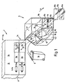
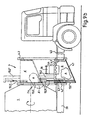
- FIG. 1 shows an example of an exploded view inventive system with feed device (4) Transport (6) on a not shown Vehicle in front of the vehicle in the longitudinal direction (arrow X) located divided storage space container (1) with the stacked storage spaces (1a, 1b), insertion openings (2a, b) for two waste fractions (A, bottom and B, top) and Closure devices (here slide 3a, 3b) for the Storage spaces and an underlying, integrated Transport device (8, 10, 11).
- the feed device (4) has a feeder shovel (6) as a means of transport, which can be pivoted upward about an axis (7) in position 6 ' is and thus also serves as a lifting device for waste.
- a waste fraction A in the lower storage space (1a) is to be introduced, for example, as follows Procedure: Before filling garbage A into the Feeder device (4) is used as the means of transport Feeder bucket (6) so far in the upper position (6 ') brought that the garbage A through the opening (5) on the (here bottom of the feeder device (4) falls. Then when the garbage container closes the opening (5) leaves, the feeder blade (6) moves in an approximately vertical position (arrow 6 '') down and transported the garbage A on the back into the opening (9a) of the Press-in channel (8a), where a transport device Press plate (10a) and hydraulic cylinder (11a) the garbage A through the press or feed channel (8a) in the lower storage space (1a) transported through the filling opening (2a).
- the feeder device (4) also serves to receive a Waste fraction (here B), which through the opening (5) of the Feeder device (4) in the feeder blade (6, lower Position) by a lifting / tilting device, not shown is filled from a household waste container (16) and between the side walls (4.1, 4.2) of the feeder device (4.) the feeder bucket (6) by rotation about the axis (7) to an injection channel (8b) through a on the top of the Press channel (8b) located opening (9b) (Empty position 6 'of the feeder bucket).
- a Waste fraction here B
- waste A or B is passed through the press channel (8a, 8b) by means of a press plate (10a, 10b) in the direction of the arrow a hydraulic cylinder (11a, 11b) through the Storage container opening (2b) in a known manner in the Storage space (1a, 1b) introduced.
- This can, if as individual swap body is designed by means of Closure (3a, 3b) closed with drive (3.1b) and be exchanged for an empty one.
- a shared Storage space has corresponding openings (2a, 3a) for the partial storage spaces (1a, 1b).
- Different variants of Storage spaces and their handling describe the DE 198 48 698.7 and DE 199 16 948.9, the use here can find.
- this feeder device With removable storage spaces (swap bodies) it is with this feeder device also possible in addition to shared or separate storage spaces also a mono storage space use if the vehicle is in the meantime for a undivided material collection, e.g. in densely populated Areas to be used.
- the arrangement of the Storage space opening (s) (2a, 2b) must then be arranged at the container-side mouth of the feed channel or Feed channels (8a, b) correspond. If you use apart lying storage space openings, one reaches in the storage space more uniform compression.
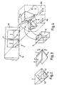
- FIG. 2 shows in another version the means of transport for Types of waste (A, B) to the transport facilities (feed channels 8a, 8b).
- the means of transport as a feeder shovel (6) with a closable bottom opening (13.1) educated.
- the garbage A can then go down to the opening 9a of the feed channel (8a) by means of a slide (13, opened 13 ') closable opening (13.1) in the Falling shovel (6) fall through (or through a Feeder plate, similar to Fig. 3 and with slide analogous to Fig. 2), so that the feeder device does not have its outer end to a level in the area above the filling opening (5) Must be raised when a faction is down is pouring.
- the slide (13) is after loading the Garbage through its opening (13.1) in the feeder shovel (6) closed. He then swivels around the - as described above Axis of rotation (7) down and presses the garbage A on his Bottom through the opening (9a) in the feed channel (8a) and thus actively from the filling side of the garbage into a more distant position.
- the means of transport (6) takes the Garbage as described and transported it over the axis (7) to the feed channel (8b).
- This version saves Travel paths for the means of transport (6) and thus time the positioning for you depending on the type of waste. The garbage workers can then still with the lifting / tilting device work faster.
- the garbage can also be in feed channels one above the other (e.g. according to FIG. 6) be granted. It is state of the art, means of Detection of the different waste containers and fractions provided. Accordingly, the positioning of the Means of transport and further material management too done automatically.
- FIG. 3 shows another version of the means of transport. It here consists of two parts - especially for the quick Transport of two waste fractions (A, B) in use of Mekam-2 vessels (these are multi-chamber vessels with one Partition parallel to the cover axis (axis see FIG. 4, Pos. E, but right-angled partition) of the waste container (16)): In the filling position, both feeder leaves of the Feeder device adjacent to each other in a known manner outside in position against the partition of the waste bin brought so that a fraction (B) of the garbage up to comes and the other (A) down into the (Cylinder segment-shaped) housing (15) falls (see FIG. 7).
- the upper feeder sheet then transports fraction B in described way to the injection channel 8b, the lower the Fraction A to the channel opening 8a. So if necessary, no Garbage from the filling opening (5) of the feeder device (4) when lifting the feeder blade If the transport means (6) falls out, the filling opening (5) by means of an adapted to the outer radius of the blade (6), cylinder-segment-shaped sliding cover (item 5.1 in FIG. 7 and upper arrow) closed.
- the bottom sheet acts like described above for the further transport of the lower fraction.
- Feeder devices (4) e.g. with easier Feeder plate (6) also comes with the use of a Mekam-2 bin and a Mekam-1 bin ("right / left" divided, see Fig. 4, item 16 and DE 15 58 433) in question.
- the Container partition against a partition of two in Vehicle longitudinal direction lying directly next to each other Feeder devices positioned e.g. in FIG. 4 with different positions of the loading buckets shown Inner cheeks of the blades form the partition).
- a cheek or Wall-separate means of transport (6) such as containers, plates etc.
- a double fill - i.e. with two lifting / tipping devices which independently for different materials (A, B) should be suitable - becomes simultaneous independent emptying in particular of two Mono garbage containers double and in the means of transport Vehicle longitudinal direction (X) arranged one behind the other.
- the Transport device e.g. from feeding or pressing unit with Press sheets (10a, b) are largely below the two Feeder devices (4). It can be your own or shared Feed channels for the respective feeder device (4) be provided.
- the drawer length of the hydraulic cylinder is to be provided according to the distances that the Further transport of the garbage to the storage space must be covered. It is also possible, as previously described two Feeder blades (6) directly in the axial direction - without separating housing - to be installed side by side and the Garbage container (16) in, under or through the respective Empty means of transport.
- FIG. 4 shows a version in which the garbage fractions are it from a multi-chamber waste container as shown, either from monotons - with this transport device also in vertically divided, i.e. one behind the other in the X direction lying storage spaces (partition 17) can be loaded by a Fraction again through the means of transport to one of the Filler opening is transported further away.
- the Feed channels (8a, 8b) take the in a known manner Types of waste (A, B) and lie next to each other for this purpose.
- the Waste fractions are then like in the storage compartments (1a, 1b) described with a feeder cleared.
- FIG. 5 shows another version for the simultaneous Recording of two waste fractions (A, B) with only one Feeder shovel (6) as a means of transport.
- This is with two Chambers (6a, b) equipped by a partition (12) be formed.
- the position of the feeder bucket is located when filling in the lower, receiving position.
- the Garbage B can then go up / back in as described above the press channel 8b are transported and the garbage A as above described down / back by putting on the back of the Shovel a slide (FIG. 2, item 13) or a flap (FIG. 5, item 13) is opened when the blade (6) in the forward / upward inclined position.
- the garbage then falls through the opening on the back of the bucket then e.g. closed by a hydraulic system and - how described above - the garbage A is through the closed Rear side to the feed channel (8a) through the opening (9a) transported from where it correspondingly into the lower storage space further reaches.
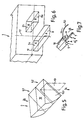
- FIG. 6 schematically shows an advantageous arrangement of FIG Feeders (channels 8a, 8b) to the storage spaces. She are against each other both laterally and in height offset and can thus both the supply to one vertically and horizontally divided storage space (dividing lines indicated by dash-dotted lines). This is for one universal container change, but also for one Series production of importance.
- This device can as mentioned, e.g. B. by pressing plates, but also simply by an inclined container bottom can be integrated.
- Advantageous is then used, for example, in particular when using power-operated contribution means or one Conveying device such as press plates (10a, 10) and removable storage space the means of transport (6, 6.8) on Storage container attached (e.g. by detachable locks such as bolts, hooks, etc.), so that a fixed counter bearing location over the chassis for holding the means of transport is eliminated can.
- the actuation of the loading shovels is on the Axis (7) not shown. It is preferably done via Known hydraulic cylinders, which preferably save space the side opposite the filling opening are. So the loading station is optimally narrow and allowed the use of longest possible storage spaces.
- FIG. 8 schematically shows a further variant of a inventive feeder device (4), which is in simple way to collect up to four (A, B, C, D) or more waste components.
- A, B, C, D waste components
- the feeder bucket is simple Carrier or catcher, e.g. a flat plate, similar to FIG. 3 or 7, replaced, but it is not a double sheet.
- This device (6.8) can be used in a shaft height adjustable as described above (see arrow Z) or slidable to the side (arrow X) be and so the garbage to positions for storage openings lead the one another at a greater distance respectively lie side by side for different storage space openings.
- This variant is indicated by arrows (Z in height, X in Width).
- the means of transport (6.8) is only in one individual feed shaft (19), the right one is advantageous Shaft wall (19r) as a closed plate without breakthrough educated.
- Shaft (20) becomes the means of transport (6.8), for example designed to be rotatable about an axis (7) and transported through a rotary movement of the garbage into the secondary shaft (20).
- the transport of the individual fractions is done in the example follows: In the left shaft (19), fraction A is down loaded by the means of transport (6.8, a flap) at the Empty the waste container (16) in a vertical position is.
- Fraction A falls through the opening that the folded up means of transport (6.8) releases in the lower Part of the shaft (19) and is there by another Transport device (press plate with press channel or from one Belt, scraper or walking floor, pouring channel, also integrated as a sloping floor in the means of transport or the like.) in the not shown storage chamber of the garbage truck transported.
- the flap (6.8) remains in for the introduction of fraction B. horizontal position and thus forms a floor.
- the Opening (18) in the partition (19r) is not one illustrated slide closed smoothly, whereupon the garbage accordingly with one assigned to this shaft segment further transport device to storage space B des Garbage container arrives.
- the flap (6.8) is again horizontal Position, the opening (18) remains open.
- Feeder blades (6, examples Fig. 1) accordingly in Arrange row to multiple fractions in the X direction or load diagonally upwards. This is about make sure that the loading buckets are arranged and clocked in this way that they do not interfere with each other and that Correctly collect waste fractions.
- FIG. 9a shows a further version of a means of transport, that as a U-shaped tub in a not shown Housing designed and slidable in the Z and / or X direction is.
- a means of transport that as a U-shaped tub in a not shown Housing designed and slidable in the Z and / or X direction is.
- the drive takes place preferably hydraulically and automatically controlled.
- the tub designed so that it is in the direction of the Working movement of the press plates (10) is open, the Contour of these press plates adapts and closely to the front and abuts the rear side walls of a feeder shaft.
- Feeder device (4) which as a container (here for Emptying by means of a sloping floor (4.1), which is another Transport device acts) in a guide frame (4.2) via drive means such as a hydraulic system, not shown a lower to a filling position (shown in dash / Dot lines), at the opening of a storage space (2a), is mobile.
- the path of the guide frame (4.2) leads at the same time transversely to the longitudinal direction of the vehicle inwards.
- the means of transport (6) is also connected to one Bracket (13.2, 13.2 '), with hydraulic actuation (13.3,13.3') attached slide valve (13, 13 ') and an opening (13.1, 13.1 ') and takes only one in the example Sort of garbage.
- the means of transport can be lowered so far be that it is partially below the height of the vehicle chassis (20) or a vehicle swap bridge.
- the paths for the lifting / tilting device (4.3) are kept short and even one Manual loading of the means of transport (6), e.g. For Garbage bags without effort is possible. It will be advantageous Volume of the means of transport (6) chosen so that it Filling several garbage containers (16) or several garbage bags picks it up in its upper position in the storage space or the storage space is emptied.
- the fault lines (4.5) indicate that in addition to the shown feeder are another can, which in a known manner advantageously over known Press channels in the storage chamber (s) is emptied. Naturally can also both means of transport (6) for emptying Press channels, e.g. through floor openings.
- the storage space (1) is an example of a known rotary drum educated.
- Household waste containers (16) are with a lifting and tipping device (4.3), here with comb bar (4.4), into the Transport means emptied in its lower position (6).
- the means of transport can be used instead of the guide frame (4.2) (6) also through movable brackets such as Hydraulic devices, guide arms or the like guided become. This has the additional advantage that it is in the lower, the garbage collecting position after the Vehicle out of the vehicle profile and the Rubbish bins can be driven towards the loading routes further shorten.
- Multi-chamber containers with one behind the other (across to Vehicle longitudinal axis) lying chambers are formed.
- the Storage space openings are corresponding to the openings of the Adapt means of transport.
- the means of transport (6) can be used as a kind of segmented drum (corresponding to a Revolver850) trained, the garbage on Outer jacket filled and then by rotating the drum respective transport device or storage space opening is forwarded.
- the lifting / tipping device is either blocked until the end position of the means of transport is established, or the Gripper coordinates to the (best then stationary) Path position of the means of transport introduced.
- the entire facility is suitable with a coordinated process of the feeder elements both for the precise insertion various garbage fractions in storage spaces that are horizontal or divided vertically or both horizontally and vertically are.
- the active feeder device can also be used for a mono storage space and for the collection of only one Waste type can be used. It will only be used for this used, it also enables the use of a low-lying pouring edge for the waste containers and thus in the Shorter cycle times compared to previous designs the pouring device.
- the means of transport can also initially only for a mono vehicle, which what can later be expanded to a multi-chamber vehicle regarding the decision to purchase vehicles from Meaning is.
- the attachment of the feeder device (4) or Means of transport (6) behind the cab and in front of the Storage container advantageously allows the construction of a Entire unit (modular principle), which is also easy to assemble can be attached to the chassis.
- attached to the sides of the storage space Cradles can also be used here with lifting / tilting devices - also automated - work and the volume loss of the storage spaces is low.
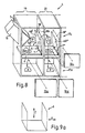
- FIG. 9b it is also possible to use one Sideloader with this active means of transport with a around its longitudinal axis rotating drum (round arrow) as Build storage space so that gfls. also different factions into the (e.g. also radially segmented or concentric divided) drum by means of a lifting means of transport can be loaded.
- the storage drum is loaded by several fractions behind the means of transport (6) by turning it into its correct one Filling compartment position brought.
- the drum can be used as usual Fill area to be provided with crushing bars inside For example, crushing residual waste and organic waste. Will she rotated, the garbage condenses in a known manner Shifting and falling.
- Emptying the storage drum is preferably carried out on the opposite side with individual doors for each segment that are locked open.
- Such a rotary drum sideloader vehicle is required not necessarily an inclination device for the vehicle bridge for emptying.
- these storage drums can also be used for long-distance transport on swap bodies made interchangeable his.
- the means of transport - or an intermediate container after the Means of transport - can also be used as a weighing device for waste or its factions are used, especially if one smoothly working loading shovel or a container (Fig.9b) are used.
- the in Loader filled (partial) amount of waste in a known Weighed wisely can be used.
- multi-chamber garbage can a weighing of the entire garbage can during its Upward movement in the lifting / tilting device in the usual way Done, then part of the content in Weighed means of transport or an intermediate container. Weighing devices on lifting and tipping devices for determination the weight of garbage are known.
- the different Weights of the fractions can now either be taken from the Measurement of the total weight at the bed minus that Weight of the partial flow measurement in one or more Determine “intermediate containers", but also exclusively static after pouring into the intermediate container.
- the latter is technically simpler because of the weighing devices on the lifting / tilting device during the lifting process have to work dynamically and through the travel path Acceleration and vibrations due to the lifting process require tremendous technical effort while measuring preferably in the proposed Intermediate containers (s) or feeding devices static can be made much easier.
- the weighing process takes a very short time and interferes with the process of the Not garbage shop.
- FIG. 1 a weighing container mentioned also a separate part, for example a cover for a Can represent transport channel, which then e.g. on feathers (18) is stored. If there is more vertical space available, e.g. also by moving the control device vertically, so can also be a larger one provided over the baling channel Intermediate container with lockable bottom the fraction temporarily pick up for weighing before moving through the floor is dropped into the baling channel from above.
- FIG. 4 with a sketch (dash / dot / dot / dash) indicated.
- Weighing in other means of transport for example in Fig.9a and 9b are shown.
- FIG. 10 shows an example of such a device in which the emptying opening (34) for reasons of adaptation to others Takeover systems should not be enlarged:
- the container advantageously has on the sides the single lid (31a, 31b) cheeks (32a, 32b), so none Garbage can fall out laterally when the partial lid is opened. The length of the lids can vary his.
- FIG. 11 shows a version in which the container lid (31), here by columns (35), against tilting in Guide bushings (36) guided parallel to it Lock position opens.
- FIG. 12 shows another example in which the whole Container lid (31) is opened to a large end Achieve outlet opening (34). Close the lids itself due to gravity after emptying again and can be closed by bolts or the like are so that they do not after pressing in the material expand at the top.
- the amount of The individual covers (31a, 31b) can be opened by stops or mutual safety devices (e.g. bolts on one Cover or one side that is in the eyelets of the other cover or run, chains etc.) are limited.
- stops or mutual safety devices e.g. bolts on one Cover or one side that is in the eyelets of the other cover or run, chains etc.
- Around the container to maintain the necessary stability Guides can be provided, the outward movement of others Counteract sides (see e.g. FIG. 11, items 35 and 36).
Landscapes
- Engineering & Computer Science (AREA)
- Mechanical Engineering (AREA)
- Refuse Collection And Transfer (AREA)
- Refuse-Collection Vehicles (AREA)
Description
Zugleich wird eine Einrichtung geschaffen, die das Wiegen verschiedener Müllfraktionen aus einem Mehrkammer-Müllbehälter ermöglicht. Ferner wird die Entleerbarkeit von Stauräumen von Müllfahrzeugen verbessert.
Auch wird der Müll nur auf der Unterseite eines Stauraumes eingebracht, so daß dessen Füllung nicht optimal erfolgt.
Claims (20)
- Müllsammel- und Transportsystem unter Verwendung eines als Seitenlader ausgebildeten Müllfahrzeuges mit einem Stauraumbehälter mit wenigstens einer Stauraumkammer (1) für die Aufnahme wenigstens eines Abfallstoffes (A, B, C, D), wobei das Müllfahrzeug an einer Fahrzeugseite wenigstens eine Öffnung (5) zu einer Zuführeinrichtung (4) zum Transport des Mülls aufweist, wobei die Zuführeinrichtung (4) zumindest eine erste, kraftbetätigte Transporteinrichtung (6, 6.8) aufweist, welche den Müll in eine vertikale (Z) und/oder horizontale (X) Richtung zu einer weiteren Transporteinrichtung (8, 10, 11) führt, mittels welcher der Müll in zumindest eine Stauraumkammer (1) eingebracht wird, dadurch gekennzeichnet, dass Mono- oder Mehrkammermüllbehälter (16) mittels einer Hub-Kippvorrichtung jeweils handhabbar sind, wobei der Müll aus den Müllbehältern (16) der ersten, quer zur Fahrzeuglängsrichtung wirkenden Transporteinrichtung (6, 6.8) zugeführt wird, die eine parallel zur Fahrzeuglängsachse wirkende Wirkachse aufweist und welche den Müll an die zweite, in Fahrzeuglängsrichtung wirkende Transporteinrichtung (8, 10, 11) weitergibt, wobei sich die erste, querwirkende und die zweite, längswirkende Transporteinrichtung frontseitig vor dem Stauraumbehälter mit Stauraumkammern (1, 1a, 1b) des Müllfahrzeugs befinden und wobei die Stauraumkammern (1, 1a, 1b) über wenigstens eine frontseitige Öffnung (2a, 2b) mittels der zweiten Transporteinrichtung (8, 10, 11) befüllt wird.
- Müllsammel- und Transportsystem nach Anspruch 1, dadurch gekennzeichnet, dass das Transportmittel (6, 6.8) der Zuführeinrichtung (4) als Müll aufnehmende Schaufel oder als Leitplatte oder als Behälter mit oder ohne Trennwand ausgebildet ist und bevorzugt eine Verschlussvorrichtung (13) besitzt, die dem Durchfallen des Mülls dient, oder dass das Transportmittel (6, 6.8) aus zumindest einem Transportschacht (19, 20) besteht, in welchem zumindest eine drehbare Klappe (6) oder eine verschiebliche Platte, Schale (6) oder dergl. angeordnet ist, welche eine Zuführung des Mülls zu einem weiteren Transportmittel (6, 6.8) bewirkt.
- Müllsammel- und Transportsystem nach Anspruch 1 oder 2, dadurch gekennzeichnet, dass für die Einbringung des Mülls in einen Stauraum (1) der Zuführeinrichtung (4) zumindest ein Einpresskanal (8a,8b) oder eine Förderschnecke, ein Kratzboden, ein Wanderboden, eine Förderrinne, ein Schrägboden, eine Zuführschaufel oder dergl. als weitere Transporteinrichtung (9,10,11) für den weiteren Transport des Mülls (A, B, C, D) in den Stauraum zugeordnet ist.
- Müllsammel- und Transportsystem nach einem der vorhergehenden Ansprüche, dadurch gekennzeichnet, dass der Müll nach seiner Leerung in die Zuführeinrichtung (4) oberhalb und/oder unterhalb des kraftbetätigten Transportmittels (6, 6.8) zu liegen kommt, wobei eine nach oben gerichtete Bewegung des Transportmittels (6, 6.8) eine Zuführung des Mülls zu einer von mehreren weiteren Transporteinrichtungen (8, 10, 11) bewirkt, die weiter von der Einfüllöffnung (5) entfernt oder höher als eine andere Transporteinrichtung gelegen ist bzw. nach unten eine Zuführung des Mülls zu einer von mehreren Transporteinrichtungen (8, 10, 11) bewirkt, die näher an der Einfüllöffnung (5) oder tiefer als eine andere Transporteinrichtung gelegen ist.
- Müllsammel- und Transportsystem nach einem der vorhergehenden Ansprüche, dadurch gekennzeichnet, dass das Transportmittel (6, 6.8) eine Pendelbewegung über seine Achse (7) hinweg und zurück nach unten vollführen kann.
- Müllsammel- und Transportsystem nach einem der vorhergehenden Ansprüche, dadurch gekennzeichnet, dass das Fahrzeug einen auswechselbaren Mono-Stauraumbehälter (1) mit wenigstens einer Zuführöffnung (2a, 2b) zur Einbringung des Mülls (A, B, C, D) aufweist und dass wenigstens zwei Transporteinrichtungen (4) für die Einbringung des Mülls in den Stauraum vorgesehen sind.
- Müllsammel- und Transportsystem nach einem der vorhergehenden Ansprüche, dadurch gekennzeichnet, dass der Stauraum (1) um seine Längsachse, gegebenenfalls zu zumindest einer einfüllposition, drehbar ist.
- Müllsammel- und Transportsystem nach einem der vorhergehenden Ansprüche, dadurch gekennzeichnet, dass Transportschächte (8a, 8b) der Transporteinrichtung (8, 10, 11) im Falle eines waagrecht geteilten Stauraumbehälters übereinander und im Falle eines senkrecht geteilten Stauraumbehälters nebeneinander angeordnet sind.
- Müllsammel- und Transportsystem nach einem der vorhergehenden Ansprüche, dadurch gekennzeichnet, dass einem Transportschacht (8a, 8b) einer Transporteinrichtung eine Einräumvorrichtung (10, 11), insbesondere eine hydraulische Presseinrichtung (10a, 10b, 11a, 11b), zugeordnet ist.
- Müllsammel- und Transportvorrichtung nach einem der vorhergehenden Ansprüche, dadurch gekennzeichnet, dass das kraftbetätigte Transportmittel (6, 6.8) nicht stationär angebracht ist und insbesondere direkt mit einer integrierten Einräumvorrichtung (10, 11) versehen ist.
- Müllsammel- und Transportvorrichtung nach einem der vorhergehenden Ansprüche, dadurch gekennzeichnet, dass die Transporteinrichtung (8, 10, 11) an ihrer Einfüllöffnung (9a, 9b) und/oder Entleerungsseite verschließbar ist.
- Müllsammel- und Transportsystem nach einem der vorhergehender Ansprüche, dadurch gekennzeichnet, dass im Falle mehrerer, nebeneinander liegender Stauräume mehrere Transportmittel (6, 6.8) vorgesehen sind, die Elemente wie Zuführschaufel, Aufnahmevorrichtung oder eine Platte enthalten, die so getaktet sind, dass sie den Müll zum nächsten Transportmittel weitertransportieren.
- Müllsammel- und Transportsystem mit Seitenladereinrichtung nach einem der vorhergehenden Ansprüche, dadurch gekennzeichnet, dass eine Transporteinrichtung (8,10,11) zur Einbringung des Mülls in einen Stauraum (1) zumindest doppelt besteht, die nach Höhe (Z) und Seite (X) so versetzt sind, dass sie sowohl zur Einfüllöffnung eines horizontal als auch vertikal geteilten oder ungeteilten Stauraumes (1) führen.
- Müllsammel- und Transportsystem nach einem der vorhergehenden Ansprüche, dadurch gekennzeichnet, dass mehrere Transportmittel (6) vorgesehen sind, die in Fahrzeuglängsrichtung hintereinander angeordnet sind, wobei das Transportmittel (6) bevorzugt aus zumindest zwei Teilen besteht, die koaxial hintereinander liegen und getrennt steuerbar sind.
- Müllsammel- und Transportsystem nach einem der vorhergehenden Ansprüche, dadurch gekennzeichnet, dass mehrere Transportmittel (6) aus zwei übereinander liegenden Teilen bestehen, die um dieselbe Drehachse (7) beweglich angeordnet und miteinander koordiniert steuerbar sind.
- Müllsammel- und Transportsystem nach einem der vorhergehenden Ansprüche, dadurch gekennzeichnet, dass das Müllfahrzeug einen auswechselbaren, geteilten oder ungeteilten Stauraum (1) aufweist, wobei bei einem Mono-Stauraum dieser eine Mehrzahl von Zuführöffnungen (2a, 2b) besitzt, die der Einbringung des Mülls dienen und mit den Transporteinrichtungen (8, 10, 11) nach Lage und Zahl übereinstimmen oder eine Einfüllöffnung (2) so angeordnet besitzt, dass diese zumindest mit einer von mehreren Transporteinrichtungen korrespondiert oder mit einem beweglichen Transportmittel (6, 6.8) angefahren wird, wobei insbesondere die Transporteinrichtung (8,10,11) am Transportmittel (6,6.8) angeordnet ist.
- Müllsammel- und Transportsystem nach einem der vorhergehenden Ansprüche, dadurch gekennzeichnet, dass der hinter dem Transportmittel gelegene Stauraum um seine Längsachse drehbar gelagert ist und von einem quer zu seiner Achse arbeitenden Transportmittel (6) (z. B. Behälter, gfls. mit einem Schrägboden) oder über eine weitere Transporteinrichtung (8,10,11) beschickt wird.
- Müllsammel- und Transportsystem nach einem der vorhergehenden Ansprüche, dadurch gekennzeichnet, dass das Transportmittel (6, 6.8) derart beweglich geführt ist, dass es in seiner unteren Position zur Müllaufnahme zumindest teilweise unterhalb des Chassis bzw. der Fahrzeugbrücke oder seitlich außerhalb des Fahrzeugprofiles positioniert ist.
- Müllsammel- und Transportsystem mit einer Hub-/Kippeinrichtung nach Anspruch 1 und einer Wiegeeinrichtung, dadurch gekennzeichnet, dass zur Bestimmung des Gewichts des Mülls oder zumindest einer Fraktion aus dem Müllbehälter zumindest ein Aufnahmemittel vorgesehen ist, dem eine Wiegevorrichtung (18) zur Wiegung des Mülls bzw. einer Müllfraktion zugeordnet ist, wobei insbesondere als Aufnahmemittel eine Schaufel (6), ein Behälter, eine Platte oder dergleichen vorgesehen ist, wobei insbesondere auch die Hub-/Kippeinrichtung mit einer Wiegevorrichtung versehen ist und zur Bestimmung des Gewichtes einer zweiten Fraktion die Differenzbildung aus dem Messergebnis des Gesamtgewichtes an der Hub-/Kippvorrichtung und dem Messergebnis der anderen Fraktion im Aufnahmemittel erfolgt.
- Müllsammel- und Transportsystem nach einem der vorhergehenden Ansprüche, dadurch gekennzeichnet, dass der Stauraumbehälter (1) an zumindest einer Seite (31), die nicht die Entleerungs- oder Befüllungsseite darstellt, eine Vorrichtung wie eine Drehachse oder eine Säulenführung (35) aufweist, mit welcher diese Seite teilweise oder ganz eine Bewegung in einer Richtung ausführen kann, die einer Richtung vom Behälterinneren nach außen entspricht, wobei die bewegliche Seite bevorzugt Mittel aufweist, welche der Begrenzung der Öffnung nach Weite und/oder Richtung dienen.
Applications Claiming Priority (7)
| Application Number | Priority Date | Filing Date | Title |
|---|---|---|---|
| DE19921699 | 1999-05-12 | ||
| DE1999121699 DE19921699A1 (de) | 1999-05-12 | 1999-05-12 | Müllsammel- und Transportsystem |
| DE19946265 | 1999-09-27 | ||
| DE19946265 | 1999-09-27 | ||
| DE19961904 | 1999-12-20 | ||
| DE19961904 | 1999-12-20 | ||
| PCT/DE2000/001472 WO2000069757A1 (de) | 1999-05-12 | 2000-05-11 | Müllsammel- und transportsystem |
Publications (2)
| Publication Number | Publication Date |
|---|---|
| EP1177145A1 EP1177145A1 (de) | 2002-02-06 |
| EP1177145B1 true EP1177145B1 (de) | 2003-02-19 |
Family
ID=27219141
Family Applications (1)
| Application Number | Title | Priority Date | Filing Date |
|---|---|---|---|
| EP00938537A Expired - Lifetime EP1177145B1 (de) | 1999-05-12 | 2000-05-11 | Müllsammel- und transportsystem |
Country Status (5)
| Country | Link |
|---|---|
| EP (1) | EP1177145B1 (de) |
| AT (1) | ATE232825T1 (de) |
| AU (1) | AU5389100A (de) |
| DE (2) | DE10023026A1 (de) |
| WO (1) | WO2000069757A1 (de) |
Cited By (1)
| Publication number | Priority date | Publication date | Assignee | Title |
|---|---|---|---|---|
| CN102173330A (zh) * | 2010-10-11 | 2011-09-07 | 白景魁 | 收集吊装压实运输垃圾的方法及设备 |
Families Citing this family (3)
| Publication number | Priority date | Publication date | Assignee | Title |
|---|---|---|---|---|
| WO2006086850A1 (en) * | 2005-02-18 | 2006-08-24 | Papas Ip Pty Ltd | Improvements relating to pendulum packers |
| CN110282306A (zh) * | 2019-06-25 | 2019-09-27 | 广东智然生态环境管理有限公司 | 一种拖拉机料箱垃圾收集装置 |
| CN119408874B (zh) * | 2024-12-13 | 2025-11-18 | 中建三局集团(深圳)有限公司 | 一种环保型智能建筑垃圾箱及其垃圾收运方法 |
Family Cites Families (13)
| Publication number | Priority date | Publication date | Assignee | Title |
|---|---|---|---|---|
| DE1558433C3 (de) | 1967-04-12 | 1975-11-27 | 5100 Aachen | Siedetrennung im ElektrorlieBbett |
| US4260316A (en) * | 1979-05-11 | 1981-04-07 | Leach Company | Refuse collection vehicle |
| DE3533751A1 (de) | 1985-09-21 | 1987-04-02 | Rolf Schiller | Muellsammelsystem |
| NL8702545A (nl) | 1987-10-26 | 1989-05-16 | Geesink Bv | Laadbak met meerdere compartimenten voor een afvalwagen, alsmede afvalwagen voorzien van een dergelijke laadbak. |
| NL8902432A (nl) * | 1989-09-29 | 1991-04-16 | Terberg Machines | Transportvoertuig met van weegmiddelen voorziene containerlosinrichting. |
| ES2049111T3 (es) | 1990-06-29 | 1994-04-01 | Vc Recycling Patentverwertung | Sistema de recogida de basuras y transporte. |
| US5226699A (en) * | 1991-11-15 | 1993-07-13 | Daniel Harold W O | Recycling vehicle and method with rotatable body |
| ES2134255T3 (es) * | 1992-02-10 | 1999-10-01 | Firebelt Pty Ltd | Vehiculo recolector de residuos de carga lateral. |
| CA2129629C (en) * | 1992-02-10 | 2003-12-02 | Idwall Charles Richards | A side-loading refuse vehicle |
| DK123192A (da) * | 1992-10-06 | 1994-04-07 | Bil Reno | Fremgangsmåde og udstyr til indsamling og transport af affald |
| US6120079A (en) | 1994-05-19 | 2000-09-19 | Multirec Patentverwertungs-Und Vertriebsgesellschaft Mbh | Garbage collection and transport system |
| AUPM969794A0 (en) * | 1994-11-28 | 1994-12-22 | Kellenbach, Arthur | Method and apparatus for weighing garbage |
| US5931628A (en) | 1995-03-28 | 1999-08-03 | Mcneilus Truck And Manufacturing, Inc. | Manual/automated side loader |
-
2000
- 2000-05-11 AU AU53891/00A patent/AU5389100A/en not_active Abandoned
- 2000-05-11 DE DE10023026A patent/DE10023026A1/de not_active Withdrawn
- 2000-05-11 AT AT00938537T patent/ATE232825T1/de not_active IP Right Cessation
- 2000-05-11 DE DE50001279T patent/DE50001279D1/de not_active Expired - Fee Related
- 2000-05-11 EP EP00938537A patent/EP1177145B1/de not_active Expired - Lifetime
- 2000-05-11 WO PCT/DE2000/001472 patent/WO2000069757A1/de not_active Ceased
Cited By (2)
| Publication number | Priority date | Publication date | Assignee | Title |
|---|---|---|---|---|
| CN102173330A (zh) * | 2010-10-11 | 2011-09-07 | 白景魁 | 收集吊装压实运输垃圾的方法及设备 |
| CN102173330B (zh) * | 2010-10-11 | 2014-01-01 | 白景魁 | 收集吊装压实运输垃圾的方法及设备 |
Also Published As
| Publication number | Publication date |
|---|---|
| DE10023026A1 (de) | 2001-02-15 |
| EP1177145A1 (de) | 2002-02-06 |
| DE50001279D1 (de) | 2003-03-27 |
| AU5389100A (en) | 2000-12-05 |
| ATE232825T1 (de) | 2003-03-15 |
| WO2000069757A1 (de) | 2000-11-23 |
Similar Documents
| Publication | Publication Date | Title |
|---|---|---|
| EP0405345B1 (de) | Abfallsammelfahrzeug | |
| DE2558433C3 (de) | Müllsammei- und Transportsystem | |
| DE4020221A1 (de) | Fahrzeug zum einsammeln von abfaellen | |
| DE69706079T2 (de) | Fahrzeug zum Sammeln und Verdichten von Müll | |
| EP0759880B1 (de) | Müllsammel- und transportsystem | |
| DE69515966T2 (de) | Mehrkammerkippwagen mit beweglichem Boden | |
| DE3121323C2 (de) | Müllfahrzeug | |
| EP0776306B1 (de) | Vorrichtung zum sammeln, einladen und transportieren von müll | |
| DE4121442C2 (de) | Müllsammel- und Transportsystem | |
| DE1297640B (de) | Strassenkehrmaschine | |
| EP1177145B1 (de) | Müllsammel- und transportsystem | |
| DE3720442C2 (de) | ||
| DE1531763A1 (de) | Muellsammel- bzw. Abfuhreinrichtung | |
| DE69602328T2 (de) | Müllsammelfahrzeug | |
| DE69400482T2 (de) | Vorrichtung und Verfahren zum getrennten Sammeln und Verdichten von Müll in einem Müllsammelfahrzeug | |
| DE3923736A1 (de) | Muellsammelfahrzeug | |
| DE69600944T2 (de) | Vorrichtung zum getrennten Sammeln von Müll | |
| DE20018056U1 (de) | Müllsammel- und Transportsystem | |
| EP3842223A1 (de) | Vertikal-kasten-ballenpresse sowie verfahren zu ihrem betrieb | |
| EP1044900A1 (de) | Müllfahrzeug in Systembauweise | |
| DE69401753T2 (de) | Abdichtungsvorrichtung für auswechselbare behälter | |
| EP0947447A1 (de) | Wechselbehälter für den Mülltransport | |
| DE19921699A1 (de) | Müllsammel- und Transportsystem | |
| DE8908724U1 (de) | Müllsammelfahrzeug | |
| DE2423023A1 (de) | Fahrzeug zum sammeln von muell |
Legal Events
| Date | Code | Title | Description |
|---|---|---|---|
| PUAI | Public reference made under article 153(3) epc to a published international application that has entered the european phase |
Free format text: ORIGINAL CODE: 0009012 |
|
| 17P | Request for examination filed |
Effective date: 20011102 |
|
| AK | Designated contracting states |
Kind code of ref document: A1 Designated state(s): AT BE CH CY DE DK ES FI FR GB GR IE IT LI LU MC NL PT SE |
|
| AX | Request for extension of the european patent |
Free format text: AL;LT;LV;MK;RO;SI |
|
| GRAH | Despatch of communication of intention to grant a patent |
Free format text: ORIGINAL CODE: EPIDOS IGRA |
|
| GRAH | Despatch of communication of intention to grant a patent |
Free format text: ORIGINAL CODE: EPIDOS IGRA |
|
| GRAA | (expected) grant |
Free format text: ORIGINAL CODE: 0009210 |
|
| AK | Designated contracting states |
Designated state(s): AT BE CH CY DE DK ES FI FR GB GR IE IT LI LU MC NL PT SE |
|
| PG25 | Lapsed in a contracting state [announced via postgrant information from national office to epo] |
Ref country code: IT Free format text: LAPSE BECAUSE OF FAILURE TO SUBMIT A TRANSLATION OF THE DESCRIPTION OR TO PAY THE FEE WITHIN THE PRE;WARNING: LAPSES OF ITALIAN PATENTS WITH EFFECTIVE DATE BEFORE 2007 MAY HAVE OCCURRED AT ANY TIME BEFORE 2007. THE CORRECT EFFECTIVE DATE MAY BE DIFFERENT FROM THE ONE RECORDED.SCRIBED TIME-LIMIT Effective date: 20030219 Ref country code: IE Free format text: LAPSE BECAUSE OF FAILURE TO SUBMIT A TRANSLATION OF THE DESCRIPTION OR TO PAY THE FEE WITHIN THE PRESCRIBED TIME-LIMIT Effective date: 20030219 Ref country code: GR Free format text: LAPSE BECAUSE OF FAILURE TO SUBMIT A TRANSLATION OF THE DESCRIPTION OR TO PAY THE FEE WITHIN THE PRESCRIBED TIME-LIMIT Effective date: 20030219 Ref country code: GB Free format text: LAPSE BECAUSE OF FAILURE TO SUBMIT A TRANSLATION OF THE DESCRIPTION OR TO PAY THE FEE WITHIN THE PRESCRIBED TIME-LIMIT Effective date: 20030219 Ref country code: FR Free format text: LAPSE BECAUSE OF FAILURE TO SUBMIT A TRANSLATION OF THE DESCRIPTION OR TO PAY THE FEE WITHIN THE PRESCRIBED TIME-LIMIT Effective date: 20030219 Ref country code: FI Free format text: LAPSE BECAUSE OF FAILURE TO SUBMIT A TRANSLATION OF THE DESCRIPTION OR TO PAY THE FEE WITHIN THE PRESCRIBED TIME-LIMIT Effective date: 20030219 |
|
| REG | Reference to a national code |
Ref country code: GB Ref legal event code: FG4D Free format text: NOT ENGLISH |
|
| REG | Reference to a national code |
Ref country code: CH Ref legal event code: EP |
|
| REG | Reference to a national code |
Ref country code: IE Ref legal event code: FG4D Free format text: GERMAN |
|
| REF | Corresponds to: |
Ref document number: 50001279 Country of ref document: DE Date of ref document: 20030327 Kind code of ref document: P |
|
| PG25 | Lapsed in a contracting state [announced via postgrant information from national office to epo] |
Ref country code: LU Free format text: LAPSE BECAUSE OF NON-PAYMENT OF DUE FEES Effective date: 20030511 Ref country code: CY Free format text: LAPSE BECAUSE OF FAILURE TO SUBMIT A TRANSLATION OF THE DESCRIPTION OR TO PAY THE FEE WITHIN THE PRESCRIBED TIME-LIMIT Effective date: 20030511 Ref country code: AT Free format text: LAPSE BECAUSE OF NON-PAYMENT OF DUE FEES Effective date: 20030511 |
|
| PG25 | Lapsed in a contracting state [announced via postgrant information from national office to epo] |
Ref country code: SE Free format text: LAPSE BECAUSE OF FAILURE TO SUBMIT A TRANSLATION OF THE DESCRIPTION OR TO PAY THE FEE WITHIN THE PRESCRIBED TIME-LIMIT Effective date: 20030519 Ref country code: PT Free format text: LAPSE BECAUSE OF FAILURE TO SUBMIT A TRANSLATION OF THE DESCRIPTION OR TO PAY THE FEE WITHIN THE PRESCRIBED TIME-LIMIT Effective date: 20030519 Ref country code: DK Free format text: LAPSE BECAUSE OF FAILURE TO SUBMIT A TRANSLATION OF THE DESCRIPTION OR TO PAY THE FEE WITHIN THE PRESCRIBED TIME-LIMIT Effective date: 20030519 |
|
| PG25 | Lapsed in a contracting state [announced via postgrant information from national office to epo] |
Ref country code: MC Free format text: LAPSE BECAUSE OF NON-PAYMENT OF DUE FEES Effective date: 20030531 |
|
| LTIE | Lt: invalidation of european patent or patent extension |
Effective date: 20030219 |
|
| GBV | Gb: ep patent (uk) treated as always having been void in accordance with gb section 77(7)/1977 [no translation filed] |
Effective date: 20030219 |
|
| PG25 | Lapsed in a contracting state [announced via postgrant information from national office to epo] |
Ref country code: ES Free format text: LAPSE BECAUSE OF FAILURE TO SUBMIT A TRANSLATION OF THE DESCRIPTION OR TO PAY THE FEE WITHIN THE PRESCRIBED TIME-LIMIT Effective date: 20030828 |
|
| REG | Reference to a national code |
Ref country code: IE Ref legal event code: FD4D Ref document number: 1177145E Country of ref document: IE |
|
| PLBE | No opposition filed within time limit |
Free format text: ORIGINAL CODE: 0009261 |
|
| STAA | Information on the status of an ep patent application or granted ep patent |
Free format text: STATUS: NO OPPOSITION FILED WITHIN TIME LIMIT |
|
| EN | Fr: translation not filed | ||
| 26N | No opposition filed |
Effective date: 20031120 |
|
| PGFP | Annual fee paid to national office [announced via postgrant information from national office to epo] |
Ref country code: NL Payment date: 20040427 Year of fee payment: 5 |
|
| PGFP | Annual fee paid to national office [announced via postgrant information from national office to epo] |
Ref country code: BE Payment date: 20040519 Year of fee payment: 5 |
|
| PG25 | Lapsed in a contracting state [announced via postgrant information from national office to epo] |
Ref country code: LI Free format text: LAPSE BECAUSE OF NON-PAYMENT OF DUE FEES Effective date: 20040531 Ref country code: CH Free format text: LAPSE BECAUSE OF NON-PAYMENT OF DUE FEES Effective date: 20040531 |
|
| PGFP | Annual fee paid to national office [announced via postgrant information from national office to epo] |
Ref country code: DE Payment date: 20040614 Year of fee payment: 5 |
|
| REG | Reference to a national code |
Ref country code: CH Ref legal event code: PL |
|
| PG25 | Lapsed in a contracting state [announced via postgrant information from national office to epo] |
Ref country code: BE Free format text: LAPSE BECAUSE OF NON-PAYMENT OF DUE FEES Effective date: 20050531 |
|
| BERE | Be: lapsed |
Owner name: *SCHILLER ROLF Effective date: 20050531 |
|
| PG25 | Lapsed in a contracting state [announced via postgrant information from national office to epo] |
Ref country code: NL Free format text: LAPSE BECAUSE OF NON-PAYMENT OF DUE FEES Effective date: 20051201 Ref country code: DE Free format text: LAPSE BECAUSE OF NON-PAYMENT OF DUE FEES Effective date: 20051201 |
|
| NLV4 | Nl: lapsed or anulled due to non-payment of the annual fee |
Effective date: 20051201 |
|
| BERE | Be: lapsed |
Owner name: *SCHILLER ROLF Effective date: 20050531 |