EP1177808A1 - Soupape de securité - Google Patents
Soupape de securité Download PDFInfo
- Publication number
- EP1177808A1 EP1177808A1 EP01111002A EP01111002A EP1177808A1 EP 1177808 A1 EP1177808 A1 EP 1177808A1 EP 01111002 A EP01111002 A EP 01111002A EP 01111002 A EP01111002 A EP 01111002A EP 1177808 A1 EP1177808 A1 EP 1177808A1
- Authority
- EP
- European Patent Office
- Prior art keywords
- fluid
- pressure
- force
- relief valve
- aperture
- Prior art date
- Legal status (The legal status is an assumption and is not a legal conclusion. Google has not performed a legal analysis and makes no representation as to the accuracy of the status listed.)
- Withdrawn
Links
- 239000012530 fluid Substances 0.000 claims abstract description 67
- 238000007789 sealing Methods 0.000 claims abstract description 11
- 238000004891 communication Methods 0.000 claims abstract description 8
- 230000029058 respiratory gaseous exchange Effects 0.000 claims description 16
- 230000001105 regulatory effect Effects 0.000 description 3
- 230000006835 compression Effects 0.000 description 2
- 238000007906 compression Methods 0.000 description 2
- 238000006467 substitution reaction Methods 0.000 description 2
- 238000010276 construction Methods 0.000 description 1
- 230000007257 malfunction Effects 0.000 description 1
- 238000011084 recovery Methods 0.000 description 1
- 238000013022 venting Methods 0.000 description 1
Images


Classifications
-
- A—HUMAN NECESSITIES
- A61—MEDICAL OR VETERINARY SCIENCE; HYGIENE
- A61M—DEVICES FOR INTRODUCING MEDIA INTO, OR ONTO, THE BODY; DEVICES FOR TRANSDUCING BODY MEDIA OR FOR TAKING MEDIA FROM THE BODY; DEVICES FOR PRODUCING OR ENDING SLEEP OR STUPOR
- A61M16/00—Devices for influencing the respiratory system of patients by gas treatment, e.g. ventilators; Tracheal tubes
- A61M16/20—Valves specially adapted to medical respiratory devices
- A61M16/208—Non-controlled one-way valves, e.g. exhalation, check, pop-off non-rebreathing valves
-
- A—HUMAN NECESSITIES
- A61—MEDICAL OR VETERINARY SCIENCE; HYGIENE
- A61M—DEVICES FOR INTRODUCING MEDIA INTO, OR ONTO, THE BODY; DEVICES FOR TRANSDUCING BODY MEDIA OR FOR TAKING MEDIA FROM THE BODY; DEVICES FOR PRODUCING OR ENDING SLEEP OR STUPOR
- A61M16/00—Devices for influencing the respiratory system of patients by gas treatment, e.g. ventilators; Tracheal tubes
- A61M16/20—Valves specially adapted to medical respiratory devices
- A61M16/201—Controlled valves
- A61M16/202—Controlled valves electrically actuated
-
- A—HUMAN NECESSITIES
- A61—MEDICAL OR VETERINARY SCIENCE; HYGIENE
- A61M—DEVICES FOR INTRODUCING MEDIA INTO, OR ONTO, THE BODY; DEVICES FOR TRANSDUCING BODY MEDIA OR FOR TAKING MEDIA FROM THE BODY; DEVICES FOR PRODUCING OR ENDING SLEEP OR STUPOR
- A61M16/00—Devices for influencing the respiratory system of patients by gas treatment, e.g. ventilators; Tracheal tubes
- A61M16/20—Valves specially adapted to medical respiratory devices
- A61M16/208—Non-controlled one-way valves, e.g. exhalation, check, pop-off non-rebreathing valves
- A61M16/209—Relief valves
-
- F—MECHANICAL ENGINEERING; LIGHTING; HEATING; WEAPONS; BLASTING
- F16—ENGINEERING ELEMENTS AND UNITS; GENERAL MEASURES FOR PRODUCING AND MAINTAINING EFFECTIVE FUNCTIONING OF MACHINES OR INSTALLATIONS; THERMAL INSULATION IN GENERAL
- F16K—VALVES; TAPS; COCKS; ACTUATING-FLOATS; DEVICES FOR VENTING OR AERATING
- F16K17/00—Safety valves; Equalising valves, e.g. pressure relief valves
- F16K17/02—Safety valves; Equalising valves, e.g. pressure relief valves opening on surplus pressure on one side; closing on insufficient pressure on one side
- F16K17/04—Safety valves; Equalising valves, e.g. pressure relief valves opening on surplus pressure on one side; closing on insufficient pressure on one side spring-loaded
- F16K17/06—Safety valves; Equalising valves, e.g. pressure relief valves opening on surplus pressure on one side; closing on insufficient pressure on one side spring-loaded with special arrangements for adjusting the opening pressure
Definitions
- the present invention relates to a pressure relief valve and in particular to a relief valve for regulating positive end expiratory pressure (PEEP) levels within a patient breathing circuit of a mechanical breathing assist device.
- PEEP positive end expiratory pressure
- a pressure relief valve is a valve which exhibits a threshold resistance such that no fluid may flow through the valve until the fluid pressure equals a predetermined threshold value. At this time an opening force exerted by the fluid pressure on a valving element equals a counter-acting threshold closing force exerted by an actuator on the valving element. Above the threshold pressure it is important that the valve should allow high rates of fluid through-flow without any significant increase in pressure drop across the valve. This is because such a valve is typically employed to open in safety critical conditions where transfer of fluid pressure other than through the valve could have serious consequences. This is particularly true when the pressure relief valve is used as a safety valve within the patient breathing circuit.
- a pressure relief valve may also be employed within such a breathing circuit as a PEEP valve to control the positive end expiratory pressure and typically should be able to permit the through-flow of expiration gas at flow rates of up to 200 to 300 litres per minute without a significant increase in the pressure drop.
- a pressure relief valve such as a PEEP valve, typically comprises an aperture for the through-flow of a fluid towards which a moveably mounted valving means is urged with a predetermined threshold closing force generated by a biasing means.
- the valving means is a arranged with a sealing surface which co-operates with the aperture to regulate the through-flow of fluid and which can seal against the aperture with the predetermined closing force.
- the sealing surface is disposed for pressure communication with the fluid to be moveable in the direction of the fluid flow to unseal the aperture when an opening force exerted by the communicated fluid pressure exceeds the counter-acting closing force.
- valve in which fluid, the flow of which is to be regulated, is used to seal the valve in the absence of an opening force provided by a biasing element.
- the valve comprises a valve housing having a fluid inlet and a fluid outlet between which is disposed a valve face.
- the valve face has a valve aperture adjacent to which is a moveable sealing element which is moveable by an opening force exerted by the fluid in the direction of fluid flow to unseal the aperture.
- a biasing means is provided to control the position of the sealing element and to regulate the flow of fluid through the valve.
- a duct is provided to divert a portion of the fluid to act on a side of the sealing element facing away from the aperture and so provide a closing force on the element counter to and at least as large as the opening force exerted by the fluid. In the absence of an opening force from the biasing means this will cause the element to move to seal the aperture.
- a pressure relief valve as described in and characterised by the present Claim 1.
- the biasing element which usefully may be adapted to generate a variable bias force, need only be powerful enough to contribute a bias force which is the difference between the closing force generated by the fluid pressure and a predetermined threshold force which must be matched by the opening force generated by the fluid pressure as it reaches a predetermined threshold pressure before fluid pressure is relieved by the valve.
- the valving element may comprise a first surface and a smaller second surface over which surfaces the fluid pressure acts and which are mechanically connected and disposed to define opposing end wall portions of a fluid receiving chamber having therein the aperture for the through-flow of the fluid which is sealable by the first surface when moved against the direction of through-flow of the fluid.
- This provides for a relatively simple valve construction.
- the aperture may be dimensioned to provide sufficient through-flow of fluid without a significant increase in the size of the valve.
- the valve is adapted to receive expiration gas from within an expiration line of a patient breathing circuit and to provide a PEEP level within the breathing circuit which may be made adjustable by providing a bias element capable of providing a variable bias force.
- the valve 2 comprises a valve housing 4 having integral therewith a solenoid housing 6 in which is housed a solenoid 8.
- the valve housing 4 encloses a fluid receiving chamber 10 which connects to external the valve housing 4 via an inlet 12 through which fluid, such as an inspiration or an expiration gas, may be received into the chamber 10.
- the chamber 10 has opposing wall sections defined by moveable first 14 and second 16 plates which are mechanically connected by a rigid member 18 so that they are moveable in concert.
- the first plate 14 has a first surface 14' exposed to fluid pressure within the chamber 10 and the second plate 16 has a second surface 16' which is also exposed to the same fluid pressure.
- the area, A1, of the first surface 14' being greater than that, A2, of the second surface 16'.
- the first plate 14 is moveable to seal (solid lines in Fig. 1) and unseal (broken lines in Fig. 1) against a sealing ring 20 located about a periphery of an aperture 22 in the chamber 10.
- the aperture 22 connects to an outlet 24 through which fluid may leave the valve 2.
- the second plate 16 forms a rigid end wall of a collapsible wall section 26, the opposite end of which is sealed to a rigid wall section 28 of the chamber 10.
- the collapsible wall section 26 is arranged such that it is in an expanded state (as shown in Fig.
- a magnetically susceptible shaft 30 has an end 32 connected to the plate 14 and acts as a moveable core of the solenoid 8 such that by passing a current through the solenoid 8 via leads 34 the shaft 30 can urge the plate 14 towards the aperture 20 with a bias force, Fb, determined by the magnitude of the current flowing through the leads 34.
- Fb bias force
- the fluid pressure, P acts on the smaller surface 16' of the second plate 16 which has an area A2, less than A1, to produce a force F2 on the plate 16.
- the closing force, F2, and the bias force, Fb combine to generate a threshold force, Ft, which the opening force, F1, must reach before the plate 14 can move under the influence of a threshold fluid pressure to unseal the aperture 22 and relieve the fluid pressure.
- equation (4) may be used to calculate the necessary bias force, Fb, which the solenoid 8 must generate. This is less than the force which the solenoid 8 of prior art valves must generate since a part of the threshold force, Ft, in the valve 2 of the present invention is generated by the fluid pressure itself, acting on the smaller plate 16.
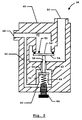
- the valve 38 comprises a valve housing 40 having integral therewith a spring housing 42 in which is housed a spring bias means 44.
- the valve housing 40 encloses a fluid duct which connects an externally accessible inlet 48 to an externally accessible outlet 50.
- An aperture 52 for the through flow of fluid is disposed within the duct 46 between the inlet 48 and the outlet 50 and is sealable by means of a first moveable plate 54 which is located directly in front of the outlet aperture 52 in the fluid flow direction through the valve 38, from inlet 48 to outlet 50 and is moveable to seal and unseal the aperture 54.
- the first plate 54 is mechanically connected to a second moveable plate 56 via a rigid rod 58 so that the two plates 54,56 can only move in concert.
- the first plate 54 is provided with a first surface 54' and the second plate 56 is provided with a smaller second surface 56' over which the fluid pressure may act.
- the second plate 56 is located within the spring housing 42 and is operably connected to the spring 44 such that a bias force, Fb', which is generated by the compression of the spring 44 is transmitted via the second plate 56 and the rod 58 to the first plate 54 to urge the plate 54 towards sealing the aperture 52.
- variable volume container 60 which is sealed at one end to the second plate 56 so as to vary its volume as the second plate 56 moves and encloses the spring 44.
- the interior of the container 60 is fluidly connected to the fluid duct 46 by means of a bypass duct 62. In this manner the second, smaller plate 56 is placed in pressure communication with fluid in the fluid duct 46, the pressure of which is to be regulated by the valve 38, only on one side of the plate 56.
- the second surface 56' of the plate 56 has an area A2' and is urged upwards when exposed to a fluid at a pressure, P', with a closing force F2' as given by substitution into equation (2).
- the same fluid pressure within the fluid duct 46 generates an opening force, F1', on the first plate 54 whose first surface 54' has an area A1' at a level given by substitution into equation (1).
- the valve 38 is to act as a PEEP valve operating at a pressure P'(PEEP) then the bias force, Fb', necessarily provided by the spring 44 is, from equation (4):
- Fb' (A1'-A2') ⁇ P'(PEEP)
- the required bias force, Fb' can be obtained by varying the compression of the spring 44 through rotating a threaded knob 64 attached to an end of the spring 44 either manually or automatically.
- FIG. 3 an embodiment of a patient breathing circuit 66 according to the present invention is shown.
- the presently illustrated breathing circuit 66 represents a circuit as is generally known in the art which has included therein a known PEEP valve.
- An inventive difference of the breathing circuit 66 of Fig. 3 is that the known PEEP valve is substituted for a PEEP valve according to the present invention, for example a valve 2,38 according to the above described exemplary embodiments. For this reason the breathing circuit 66 shall not be described in great detail.
- the breathing circuit 66 is shown to comprise a ventilator unit 68 to which ends of an inspiration gas line 70 and an expiration gas line 72 are connected for the transportation of gas respectively to and from an open end 74 of a patient tube 76, which open end 74 is intended in use to connect to the airways of a patient (not shown).
- One way valves 78, 80 are connected in-line in respective inspiration line 70 and expiration line 72 to ensure gas flows within the inspiration line 70 only in a direction towards the open end 74 and in the expiration line 72 only in a direction from the open end 74.
- a PEEP valve 2 according to the present invention is arranged in-line with the expiration line 72 with its inlet 12 connected to the expiration line 72 between the one way valve 80 and the ventilator 68 and its outlet 24 is connected via the expiration line 72 to the ventilator 68.
- the gas pressure within the expiration line 72 which will cause the valve 2 to open is controlled by current supplied by a control unit 84 (which may be incorporated within the ventilator 68) along leads 34 and is set so that the aperture 22 will remain unsealed until the pressure of the expiration gas falls to the PEEP level.
- a second relief valve 38 is incorporated in the inspiration line 70 and is arranged to act as a pressure release safety valve which operates to ensure that the pressure of inspiration gas supplied to the open end 74 does not exceed a predetermined safe maximum which may be set by adjusting the knob 64 (see Fig. 2) of the valve 38 to vary the extension of the spring bias 44 (see Fig. 2).
- a predetermined safe maximum which may be set by adjusting the knob 64 (see Fig. 2) of the valve 38 to vary the extension of the spring bias 44 (see Fig. 2).
- the inlet 48 of the valve 38 is connected (such as via a T-piece 86) to the inspiration line 70 with the outlet 50 venting to atmosphere (or a recovery system - not shown).
- the aperture 52 will remain sealed until the inspiration gas pressure within the valve 38 exceeds a threshold set at the safe maximum value. Until this threshold is exceeded the inspiration gas continues to flow from the ventilator 68, along the inspiration line 70 and to the open end 74 of the patient tube 76.
- valves 2 or 38 may be used in the inspiration line 70 and the expiration line 72 of the breathing circuit 66 or that the valves 2 and 38 may be swapped to provide the functionality described above with respect to Fig. 3 without departing from the invention as claimed. Additionally or alternatively a valve 2, 38 according to the present invention may be included in-line in the inspiration line 70 and arranged in a manner similar to that shown for valve 2 in the expiration line 72 of Fig. 3 to act as a lower pressure delimiter for gas supplied from the ventilator unit 68.
Landscapes
- Health & Medical Sciences (AREA)
- Engineering & Computer Science (AREA)
- Pulmonology (AREA)
- Life Sciences & Earth Sciences (AREA)
- General Health & Medical Sciences (AREA)
- Biomedical Technology (AREA)
- Heart & Thoracic Surgery (AREA)
- Hematology (AREA)
- Emergency Medicine (AREA)
- Animal Behavior & Ethology (AREA)
- Anesthesiology (AREA)
- Public Health (AREA)
- Veterinary Medicine (AREA)
- General Engineering & Computer Science (AREA)
- Mechanical Engineering (AREA)
- Safety Valves (AREA)
- Devices For Dispensing Beverages (AREA)
Applications Claiming Priority (2)
| Application Number | Priority Date | Filing Date | Title |
|---|---|---|---|
| SE0002805 | 2000-08-01 | ||
| SE0002805A SE0002805D0 (sv) | 2000-08-01 | 2000-08-01 | Pressure relief valve |
Publications (1)
| Publication Number | Publication Date |
|---|---|
| EP1177808A1 true EP1177808A1 (fr) | 2002-02-06 |
Family
ID=20280615
Family Applications (1)
| Application Number | Title | Priority Date | Filing Date |
|---|---|---|---|
| EP01111002A Withdrawn EP1177808A1 (fr) | 2000-08-01 | 2001-05-07 | Soupape de securité |
Country Status (4)
| Country | Link |
|---|---|
| US (1) | US20020017301A1 (fr) |
| EP (1) | EP1177808A1 (fr) |
| JP (1) | JP2002113106A (fr) |
| SE (1) | SE0002805D0 (fr) |
Cited By (4)
| Publication number | Priority date | Publication date | Assignee | Title |
|---|---|---|---|---|
| EP1400256A1 (fr) * | 2002-09-17 | 2004-03-24 | Anzai Medical Kabushiki Kaisha | Appareil de ventilation artificielle |
| CN103007408A (zh) * | 2012-11-28 | 2013-04-03 | 宁波圣宇瑞医疗器械有限公司 | 一种用于呼吸装置的调节阀 |
| CN103877658A (zh) * | 2012-12-21 | 2014-06-25 | 通用电气公司 | 一种释放阀组件 |
| WO2020249813A1 (fr) * | 2019-06-13 | 2020-12-17 | Palliare Limited | Système de contrôle de fuite pour système d'insufflation, et méthode destinée à réduire au minimum une fuite provenant d'un système d'insufflation |
Families Citing this family (27)
| Publication number | Priority date | Publication date | Assignee | Title |
|---|---|---|---|---|
| SE0200409D0 (sv) * | 2002-02-13 | 2002-02-13 | Siemens Elema Ab | Method of Controlling a Valve Element and Valve Assembly |
| GB2405799A (en) * | 2003-09-15 | 2005-03-16 | Vectura Ltd | Dry powder inhaler incorporating a valve which is opened and closed by pressurized gas |
| US9044027B2 (en) * | 2003-10-10 | 2015-06-02 | Euthanex Corporation | Method and apparatus for the euthanasia of animals |
| CN100383440C (zh) * | 2005-05-13 | 2008-04-23 | 广东正力精密机械有限公司 | 一种自动放气阀 |
| ES2372892T3 (es) * | 2007-03-08 | 2012-01-27 | Aerocrine Ab | Neumotacógrafo portátil para medir componentes del volumen espiratorio así como procedimiento para ello. |
| EP2173423B1 (fr) * | 2007-07-06 | 2017-12-20 | Maquet Critical Care AB | Valve expiratoire d'un appareil respiratoire anesthésique ayant un système auxiliaire de secours |
| CN101873875B (zh) * | 2007-09-26 | 2014-11-12 | 呼吸科技公司 | 用于在通气治疗中提供吸气和呼气流释放的方法和装置 |
| WO2009058557A2 (fr) * | 2007-10-12 | 2009-05-07 | Euthanix Corp. | Procédé et appareil pour euthanasier des animaux |
| US8302602B2 (en) | 2008-09-30 | 2012-11-06 | Nellcor Puritan Bennett Llc | Breathing assistance system with multiple pressure sensors |
| DE102010004424A1 (de) * | 2010-01-13 | 2011-07-14 | Dräger Medical GmbH, 23558 | Vorrichtung zum Druckausgleich an einer medizinischen Gasfördereinrichtung |
| US20110284007A1 (en) * | 2010-05-21 | 2011-11-24 | Pierre Peron | Positive pressure device |
| EP2389970A1 (fr) * | 2010-05-31 | 2011-11-30 | General Electric Company | Système de contrôle de la pression dans un circuit respiratoire |
| EP2431065B1 (fr) * | 2010-09-15 | 2020-04-22 | General Electric Company | Dispositif pour la ventilation des poumons |
| US9364624B2 (en) | 2011-12-07 | 2016-06-14 | Covidien Lp | Methods and systems for adaptive base flow |
| US9498589B2 (en) | 2011-12-31 | 2016-11-22 | Covidien Lp | Methods and systems for adaptive base flow and leak compensation |
| US9022031B2 (en) | 2012-01-31 | 2015-05-05 | Covidien Lp | Using estimated carinal pressure for feedback control of carinal pressure during ventilation |
| US8844526B2 (en) | 2012-03-30 | 2014-09-30 | Covidien Lp | Methods and systems for triggering with unknown base flow |
| US9492629B2 (en) | 2013-02-14 | 2016-11-15 | Covidien Lp | Methods and systems for ventilation with unknown exhalation flow and exhalation pressure |
| US9981096B2 (en) | 2013-03-13 | 2018-05-29 | Covidien Lp | Methods and systems for triggering with unknown inspiratory flow |
| US9808591B2 (en) | 2014-08-15 | 2017-11-07 | Covidien Lp | Methods and systems for breath delivery synchronization |
| US9950129B2 (en) | 2014-10-27 | 2018-04-24 | Covidien Lp | Ventilation triggering using change-point detection |
| US9925346B2 (en) | 2015-01-20 | 2018-03-27 | Covidien Lp | Systems and methods for ventilation with unknown exhalation flow |
| JP7114569B2 (ja) * | 2016-08-16 | 2022-08-08 | フィッシャー アンド ペイケル ヘルスケア リミテッド | 圧力調整弁 |
| US11324954B2 (en) | 2019-06-28 | 2022-05-10 | Covidien Lp | Achieving smooth breathing by modified bilateral phrenic nerve pacing |
| US12257437B2 (en) | 2020-09-30 | 2025-03-25 | Covidien Lp | Intravenous phrenic nerve stimulation lead |
| CN113368350B (zh) * | 2021-05-31 | 2023-12-19 | 福建智恒氢启健康科技有限公司 | 一种便携式氢氧疗养机 |
| CN120900070B (zh) * | 2025-10-11 | 2025-12-16 | 成都荣创医疗科技股份有限公司 | 一种自动补偿保压的儿科呼吸机供气机构 |
Citations (4)
| Publication number | Priority date | Publication date | Assignee | Title |
|---|---|---|---|---|
| US4367767A (en) * | 1980-12-04 | 1983-01-11 | Bear Medical Systems, Inc. | Servo-controlled gas pressure relief valve |
| US4823828A (en) * | 1987-05-28 | 1989-04-25 | Mcginnis Gerald E | Pressure relief valve |
| DD273982A1 (de) * | 1988-07-14 | 1989-12-06 | Medizin Labortechnik Veb K | Wegeventil |
| EP0911054A1 (fr) * | 1997-10-20 | 1999-04-28 | Siemens-Elema AB | Soupape |
-
2000
- 2000-08-01 SE SE0002805A patent/SE0002805D0/xx unknown
-
2001
- 2001-05-07 EP EP01111002A patent/EP1177808A1/fr not_active Withdrawn
- 2001-06-26 US US09/891,940 patent/US20020017301A1/en not_active Abandoned
- 2001-08-01 JP JP2001233684A patent/JP2002113106A/ja active Pending
Patent Citations (4)
| Publication number | Priority date | Publication date | Assignee | Title |
|---|---|---|---|---|
| US4367767A (en) * | 1980-12-04 | 1983-01-11 | Bear Medical Systems, Inc. | Servo-controlled gas pressure relief valve |
| US4823828A (en) * | 1987-05-28 | 1989-04-25 | Mcginnis Gerald E | Pressure relief valve |
| DD273982A1 (de) * | 1988-07-14 | 1989-12-06 | Medizin Labortechnik Veb K | Wegeventil |
| EP0911054A1 (fr) * | 1997-10-20 | 1999-04-28 | Siemens-Elema AB | Soupape |
Cited By (8)
| Publication number | Priority date | Publication date | Assignee | Title |
|---|---|---|---|---|
| EP1400256A1 (fr) * | 2002-09-17 | 2004-03-24 | Anzai Medical Kabushiki Kaisha | Appareil de ventilation artificielle |
| US7448381B2 (en) | 2002-09-17 | 2008-11-11 | Anzai Medical Kabushiki Kaisha | Respiration control apparatus |
| CN103007408A (zh) * | 2012-11-28 | 2013-04-03 | 宁波圣宇瑞医疗器械有限公司 | 一种用于呼吸装置的调节阀 |
| CN103877658A (zh) * | 2012-12-21 | 2014-06-25 | 通用电气公司 | 一种释放阀组件 |
| US9452275B2 (en) | 2012-12-21 | 2016-09-27 | General Electric Company | Detachable inspiratory relief valve |
| CN103877658B (zh) * | 2012-12-21 | 2017-01-04 | 通用电气公司 | 一种释放阀组件 |
| WO2020249813A1 (fr) * | 2019-06-13 | 2020-12-17 | Palliare Limited | Système de contrôle de fuite pour système d'insufflation, et méthode destinée à réduire au minimum une fuite provenant d'un système d'insufflation |
| US12558497B2 (en) | 2019-06-13 | 2026-02-24 | Palliare Limited | Leak control system for an insufflation system, and a method for minimising leakage from an insufflation system |
Also Published As
| Publication number | Publication date |
|---|---|
| JP2002113106A (ja) | 2002-04-16 |
| US20020017301A1 (en) | 2002-02-14 |
| SE0002805D0 (sv) | 2000-08-01 |
Similar Documents
| Publication | Publication Date | Title |
|---|---|---|
| EP1177808A1 (fr) | Soupape de securité | |
| US5063925A (en) | Controllable expiration valve arrangement for a ventilating apparatus | |
| US6415815B1 (en) | Pressure relief valve | |
| CN101253354B (zh) | 箱体歧管组件 | |
| CN105135014A (zh) | 用于负载调节器的内部泄放阀装置 | |
| EP0860175A2 (fr) | Ventilateur pour ventilation intensive et sa valve | |
| JPS61130677A (ja) | 流量制限弁と方法 | |
| IL31730A (en) | Valve arrangement,especially for use in anaesthetic gas supply systems | |
| EP1228781A3 (fr) | Appareil d'assistance respiratoire | |
| EP1273317B1 (fr) | Système de régulation du débit d'un fluide | |
| CA2681770C (fr) | Mecanisme de disque reglable pour regulateur a gaz | |
| CA2431871C (fr) | Electrorobinet de commande de debit | |
| WO1996019689A3 (fr) | Systeme de soupapes, notamment pour commandes pneumatiques | |
| WO2000079164A1 (fr) | Configuration de regulateur | |
| SI9700147A (sl) | Kombinacija aksialnega membranskega regulatorja z dušilko in krmilnim ventilom | |
| CN107532748A (zh) | 软节流阀 | |
| US7730885B2 (en) | Device for mixing anesthetic vapor with anesthetic gas | |
| US5875807A (en) | Flow control especially for instantaneous water heater | |
| US7121298B2 (en) | Reducer valve for pressurized gas | |
| WO2001059342A1 (fr) | Regulateur de pression de gaz hermetique | |
| US12578741B2 (en) | Pressure control valve | |
| JP2005172090A (ja) | 滅菌スチームトラップ装置 | |
| KR102590810B1 (ko) | 누설 방지 밸브 | |
| JP3513067B2 (ja) | ガス器具におけるガス流制御装置 | |
| JPS62116392A (ja) | 調整弁及びそれを備えた複動弁装置 |
Legal Events
| Date | Code | Title | Description |
|---|---|---|---|
| PUAI | Public reference made under article 153(3) epc to a published international application that has entered the european phase |
Free format text: ORIGINAL CODE: 0009012 |
|
| AK | Designated contracting states |
Kind code of ref document: A1 Designated state(s): AT BE CH CY DE DK ES FI FR GB GR IE IT LI LU MC NL PT SE TR Kind code of ref document: A1 Designated state(s): DE FR |
|
| AX | Request for extension of the european patent |
Free format text: AL;LT;LV;MK;RO;SI |
|
| 17P | Request for examination filed |
Effective date: 20020521 |
|
| AKX | Designation fees paid |
Free format text: DE FR |
|
| 17Q | First examination report despatched |
Effective date: 20030509 |
|
| STAA | Information on the status of an ep patent application or granted ep patent |
Free format text: STATUS: THE APPLICATION IS DEEMED TO BE WITHDRAWN |
|
| 18D | Application deemed to be withdrawn |
Effective date: 20030920 |