EP1178238B1 - Zweirohr-Stossdämpfer - Google Patents
Zweirohr-Stossdämpfer Download PDFInfo
- Publication number
- EP1178238B1 EP1178238B1 EP20010115578 EP01115578A EP1178238B1 EP 1178238 B1 EP1178238 B1 EP 1178238B1 EP 20010115578 EP20010115578 EP 20010115578 EP 01115578 A EP01115578 A EP 01115578A EP 1178238 B1 EP1178238 B1 EP 1178238B1
- Authority
- EP
- European Patent Office
- Prior art keywords
- shock absorber
- rod
- control cone
- axial bore
- twin
- Prior art date
- Legal status (The legal status is an assumption and is not a legal conclusion. Google has not performed a legal analysis and makes no representation as to the accuracy of the status listed.)
- Expired - Lifetime
Links
- 239000006096 absorbing agent Substances 0.000 title claims description 24
- 230000035939 shock Effects 0.000 title claims description 24
- 238000013016 damping Methods 0.000 claims description 14
- 239000012530 fluid Substances 0.000 claims description 2
- 230000001419 dependent effect Effects 0.000 description 1
- 238000011161 development Methods 0.000 description 1
- 230000018109 developmental process Effects 0.000 description 1
- 230000036316 preload Effects 0.000 description 1
Images
Classifications
-
- F—MECHANICAL ENGINEERING; LIGHTING; HEATING; WEAPONS; BLASTING
- F16—ENGINEERING ELEMENTS AND UNITS; GENERAL MEASURES FOR PRODUCING AND MAINTAINING EFFECTIVE FUNCTIONING OF MACHINES OR INSTALLATIONS; THERMAL INSULATION IN GENERAL
- F16F—SPRINGS; SHOCK-ABSORBERS; MEANS FOR DAMPING VIBRATION
- F16F9/00—Springs, vibration-dampers, shock-absorbers, or similarly-constructed movement-dampers using a fluid or the equivalent as damping medium
- F16F9/32—Details
- F16F9/44—Means on or in the damper for manual or non-automatic adjustment; such means combined with temperature correction
- F16F9/46—Means on or in the damper for manual or non-automatic adjustment; such means combined with temperature correction allowing control from a distance, i.e. location of means for control input being remote from site of valves, e.g. on damper external wall
- F16F9/466—Throttling control, i.e. regulation of flow passage geometry
-
- F—MECHANICAL ENGINEERING; LIGHTING; HEATING; WEAPONS; BLASTING
- F16—ENGINEERING ELEMENTS AND UNITS; GENERAL MEASURES FOR PRODUCING AND MAINTAINING EFFECTIVE FUNCTIONING OF MACHINES OR INSTALLATIONS; THERMAL INSULATION IN GENERAL
- F16F—SPRINGS; SHOCK-ABSORBERS; MEANS FOR DAMPING VIBRATION
- F16F9/00—Springs, vibration-dampers, shock-absorbers, or similarly-constructed movement-dampers using a fluid or the equivalent as damping medium
- F16F9/32—Details
- F16F9/50—Special means providing automatic damping adjustment, i.e. self-adjustment of damping by particular sliding movements of a valve element, other than flexions or displacement of valve discs; Special means providing self-adjustment of spring characteristics
- F16F9/512—Means responsive to load action, i.e. static load on the damper or dynamic fluid pressure changes in the damper, e.g. due to changes in velocity
Definitions
- the invention relates to a shock absorber, both as an oil and gas pressure damper, with a main damping valve and return openings on the damping piston mounted on a piston rod.
- the invention has for its object to provide a shock absorber on the Ausfederungs from outside the shock absorber can be influenced.
- a control cone is adjustable in the bypass opening and with this the cross-section of the bypass opening. This makes it possible in a simple manner, set from outside the shock absorber, the Glasdämpfungs characteristic.
- a twin-tube shock absorber which has a main damping valve and return openings on a damping piston mounted on a piston rod.
- the control cone is biased with a spring, wherein the force of the spring preload can be adjusted via an adjustment rod from outside the shock absorber.
- the position of the control cone is thus dependent on the pressure exerted on the control cone by the fluid pressure (see also JP 49 021 565).
- FR 2 418 390 a two-pipe shock absorber with an adjustable damping stage is disclosed, in which the position of a needle valve within a threaded adapter with an adjusting rod from outside the shock absorber is adjustable.
- JP 08 170 680 or in the FR 1 097 456 each show a shock absorber having a control cone which is provided within an axial bore of a threaded adapter.
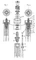
- Fig. 1 and 2 respectively in plan view and in axial section the piston with piston rod and adjustable tension damping, once with closed bypass opening and once with fully open bypass opening, and in between exploded the conventional parts of the main damping valve and the piston rod with threaded adapter and adjusting rod ,
- a threaded adapter 2 is screwed, which in turn carries the damping piston 3.
- the damping piston 3 is formed with the usual parts 4, the main damping valve.
- the threaded adapter 2 is located in the axial extension of the piston rod bore 5 has an axial bore 6, through which both holes 5 and 6, the adjusting rod 7 extends with control cone 8 at its lower end.
- the adjusting rod 7 is screwed with a Einstellgewinde 9 more or less deep into the axial bore 6 of the threaded adapter 2, between a position shown in Figure 1, in which the control cone 8 abuts against the outlet end of the axial bore 6 and closes the annular gap between the adjusting rod 7 and 6 axial bore , and a position according to Figure 2 with a maximum lifted control cone 8 and thus maximum bypass opening 13.
- the two end positions of the adjusting rod 7 are secured by end stops 10.
- the annular gap in the threaded adapter between the adjusting rod 7 and axial bore 6 is connected via an oil inlet bore 11 with the oil chamber of the shock absorber in combination.
- a seal 12 seals the piston rod bore 5 from the bypass opening in the threaded adapter 2.
- the adjusting rod 7 is from outside the twin-tube shock absorber (not shown) between the end positions of figures 1 and 2 adjustable to thereby change the bypass opening 13 and to influence the train damping characteristic.
Landscapes
- Engineering & Computer Science (AREA)
- General Engineering & Computer Science (AREA)
- Mechanical Engineering (AREA)
- Physics & Mathematics (AREA)
- Fluid Mechanics (AREA)
- Fluid-Damping Devices (AREA)
Description
- Die Erfindung betrifft einen Stoßdämpfer, sowohl als Öl- als auch als Gasdruckdämpfer, mit einem Hauptdämpfungsventil und Rücklauföffnungen an dem auf einer Kolbenstange montierten Dämpfungskolben.
- Es ist bekannt, bei einem Zweirohr-Stoßdämpfer eine Bypass-Regelung zum Verändern des Einfederungsverhaltens vorzusehen. Es ist auch bekannt, diese Bypass-Regelung von außerhalb des Stoßdämpfers einstellbar auszubilden. Das Ausfederungsverhalten des Stoßdämpfers ist dagegen konstruktiv vorgegeben und damit nicht nachträglich von außerhalb des Stoßdämpfers einstellbar.
- Der Erfindung liegt die Aufgabe zugrunde, einen Stoßdämpfer zu schaffen, auf dessen Ausfederungsverhalten von außerhalb des Stoßdämpfers Einfluss genommen werden kann.
- Diese Aufgabe wird mit einem Stoßdämpfer gemäß Anspruch 1 gelöst.
- Weiterbildungen der Erfindung sind in den Unteransprüchen beschrieben.
- Über eine Einstellstange, die sich zweckmäßig durch die hohlgebohrte Kolbenstange erstreckt, ist in der Bypass-Öffnung ein Steuerkonus und mit diesem der Querschnitt der Bypass-Öffnung einstellbar. Damit ist es in einfacher Weise möglich, von außerhalb des Stoßdämpfers die Zugdämpfungs-Kennlinie einzustellen.
- Im Stand der Technik ist gemäß der GB 694,544 ein Zweirohr-Stoßdämpfer bekannt, der ein Hauptdämpfungsventil und Rücklauföffnungen an einem auf einer Kolbenstange befestigten Dämpfungskolben aufweist. Der Steuerkonus ist mit einer Feder vorgespannt, wobei die Kraft der Federvorspannung über eine Einstellstange von außerhalb des Stoßdämpfers justiert werden kann. Die Position des Steuerkonus ist damit abhängig von dem auf den Steuerkonus durch das Fluid ausgeübten Druck (siehe ferner JP 49 021 565). Gemäß der FR 2 418 390 ist ein Zweirohr-Stoßdämpfer mit einer einstellbaren Dämpfungsstufe offenbart, in dem die Stellung eines Nadelventils innerhalb eines Gewindeadapters mit einer Einstellstange von außerhalb des Stoßdämpfers justierbar ist. Ferner ist in der JP 08 170 680 oder in der FR 1 097 456 jeweils ein Stoßdämpfer aufgezeigt, der einen Steuerkonus aufweist, der innerhalb einer Axialbohrung eines Gewindeadapters vorgesehen ist.
- Die Erfindung wird nachfolgend anhand beigefügter Zeichnungen näher erläutert. Es zeigen
- Fig. 1 und 2 jeweils in Draufsicht und im Axialschnitt den Kolben mit Kolbenstange und einstellbarer Zugdämpfung, einmal bei geschlossener Bypass-Öffnung und einmal bei voll geöffneter Bypass-Öffnung, und dazwischen in Explosionsdarstellung die konventionellen Teile des Hauptdämpfungsventils sowie die Kolbenstange mit Gewindeadapter und Einstellstange.
- Am unteren Ende der hohlgebohrten Kolbenstange 1 ist ein Gewindeadapter 2 eingeschraubt, der seinerseits den Dämpfungskolben 3 trägt. Im Dämpfungskolben 3 ist mit den üblichen Teilen 4 das Hauptdämpfungsventil ausgebildet. Im Gewindeadapter 2 befindet sich in axialer Verlängerung der Kolbenstangenbohrung 5 eine Axialbohrung 6, durch welche beide Bohrungen 5 und 6 sich die Einstellstange 7 mit Steuerkonus 8 an ihrem unteren Ende erstreckt. Die Einstellstange 7 ist mit einem Einstellgewinde 9 mehr oder minder tief in die Axialbohrung 6 des Gewindeadapters 2 einschraubbar, zwischen einer Stellung gemäß Figur 1, in welcher der Steuerkonus 8 gegen das Austrittsende der Axialbohrung 6 anliegt und den Ringspalt zwischen Einstellstange 7 und Axialbohrung 6 verschließt, und einer Stellung gemäß Figur 2 mit maximal abgehobenem Steuerkonus 8 und damit maximaler Bypass-Öffnung 13. Die beiden Endstellungen der Einstellstange 7 sind durch Endanschläge 10 gesichert. Der Ringspalt im Gewindeadapter zwischen Einstellstange 7 und Axialbohrung 6 steht über eine Öleinströmbohrung 11 mit dem Ölraum des Stoßdämpfers in Verbindung. Eine Dichtung 12 dichtet die Kolbenstangenbohrung 5 gegenüber der Bypass-Öffnung im Gewindeadapter 2 ab.
- Die Einstellstange 7 ist von außerhalb des Zweirohr-Stoßdämpfers (nicht gezeigt) zwischen den Endstellungen von Figuren 1 und 2 einstellbar, um dadurch die Bypass-Öffnung 13 zu ändern und auf die Zugdämpfungs-Kennlinie Einfluß zu nehmen.
Claims (4)
- Stoßdämpfer, sowohl als Öl- als auch als Gasdruckdämpfer, mit einem Hauptdämpfungsventil und Rücklauföffnungen an einem auf einer Kolbenstange (1) über einen Gewindeadapter (2) befestigten Dämpfungskolben (3) und mit einer einstellbaren Zugdämpfung,wobei der Gewindeadapter (2) eine eine Bypass-Öffnung (13) bildende Axialbohrung (6) aufweist, und wobei die einstellbare Zugdämpfung einen Steuerkonus (8) und eine Einstellstange (7) umfasst, wobei die Einstellstange (7) die Stellung des Steuerkonus (8) und mit diesem den Querschnitt der Bypass-Öffnung (13) von außerhalb des Stoßdämpfers einstellt; wobei die Axialbohrung (6) des Gewindeadapters (2) an der der Kolbenstange (1) abgewandten Seite des Dämpfungskolbens (3) ein Austrittsende aufweist, das einen Ausströmort des Fluids für die Zugstufe bildet,
dadurch gekennzeichnet, dass der Steuerkonus (8) am Austrittsende der Axialbohrung (6) des Gewindeadapters (2) vorgesehen ist, und dass der Stoßdämpfer als ein Zweirohr-Stoßdämpfer ausgebildet ist. - Stoßdämpfer nach Anspruch 1,
dadurch gekennzeichnet, dass der Steuerkonus (8) am Ende der Einstellstange (7) sitzt. - Stoßdämpfer nach Anspruch 1 oder 2,
dadurch gekennzeichnet, dass sich die Einstellstange (7) durch die hohlgebohrte Kolbenstange (1) erstreckt. - Stoßdämpfer nach einem der vorangehenden Ansprüche,
gekennzeichnet durch Endanschläge (10) zur Begrenzung des Einstellbereichs der Einstellstange nach beiden Richtungen.
Applications Claiming Priority (2)
| Application Number | Priority Date | Filing Date | Title |
|---|---|---|---|
| DE20013228U DE20013228U1 (de) | 2000-07-31 | 2000-07-31 | Zweirohr-Stossdämpfer |
| DE20013228U | 2000-07-31 |
Publications (3)
| Publication Number | Publication Date |
|---|---|
| EP1178238A2 EP1178238A2 (de) | 2002-02-06 |
| EP1178238A3 EP1178238A3 (de) | 2003-06-18 |
| EP1178238B1 true EP1178238B1 (de) | 2006-08-30 |
Family
ID=7944633
Family Applications (1)
| Application Number | Title | Priority Date | Filing Date |
|---|---|---|---|
| EP20010115578 Expired - Lifetime EP1178238B1 (de) | 2000-07-31 | 2001-06-28 | Zweirohr-Stossdämpfer |
Country Status (3)
| Country | Link |
|---|---|
| EP (1) | EP1178238B1 (de) |
| DE (2) | DE20013228U1 (de) |
| ES (1) | ES2267634T3 (de) |
Family Cites Families (8)
| Publication number | Priority date | Publication date | Assignee | Title |
|---|---|---|---|---|
| BE506125A (de) * | 1950-10-31 | |||
| DE910868C (de) * | 1952-09-07 | 1954-05-06 | Hemscheidt Maschf Hermann | Hydraulischer Teleskopschwingungsdaempfer, insbesondere fuer Kraftfahrzeuge |
| FR1097456A (fr) * | 1954-03-30 | 1955-07-06 | Amortisseur télescopique réglable extérieurement par l'axe de la tige de piston | |
| JPS4921565A (de) * | 1972-06-23 | 1974-02-26 | ||
| FR2418390A1 (fr) * | 1978-02-24 | 1979-09-21 | Bourcier Carbon Christian | Amortisseur hydraulique telescopique reglable perfectionne |
| DE7920645U1 (de) * | 1979-07-19 | 1979-10-25 | Stabilus Gmbh, 5400 Koblenz | Auslöseeinrichtung für das Blockierventil einer Gasfeder |
| JPS5817277A (ja) * | 1981-07-22 | 1983-02-01 | Kayaba Ind Co Ltd | 伸縮ロツク装置における開閉弁装置 |
| JP3198843B2 (ja) * | 1994-12-20 | 2001-08-13 | トヨタ自動車株式会社 | 減衰力可変式ショックアブソーバ |
-
2000
- 2000-07-31 DE DE20013228U patent/DE20013228U1/de not_active Expired - Lifetime
-
2001
- 2001-06-28 ES ES01115578T patent/ES2267634T3/es not_active Expired - Lifetime
- 2001-06-28 DE DE50110857T patent/DE50110857D1/de not_active Expired - Lifetime
- 2001-06-28 EP EP20010115578 patent/EP1178238B1/de not_active Expired - Lifetime
Also Published As
| Publication number | Publication date |
|---|---|
| DE50110857D1 (de) | 2006-10-12 |
| DE20013228U1 (de) | 2001-01-25 |
| ES2267634T3 (es) | 2007-03-16 |
| EP1178238A3 (de) | 2003-06-18 |
| EP1178238A2 (de) | 2002-02-06 |
Similar Documents
| Publication | Publication Date | Title |
|---|---|---|
| DE4223673C2 (de) | Druckbetätigte Ventilanordnung im kolben eines Stossdämpfers | |
| DE3712477C2 (de) | ||
| DE112016000579B4 (de) | Sekundäre dämpfungsanordnung für einen stossdämpfer | |
| DE19749356B4 (de) | Zweistufiger Stoßdämpfer mit hubabhängiger Dämpfung | |
| DE3932669C2 (de) | Hydraulischer Stoßdämpfer | |
| DE19948328B4 (de) | Schwingungsdämpfer mit zweistufiger Dämpfung | |
| DE19807211B4 (de) | Schwingungsdämpfer | |
| DE102012014583B4 (de) | Ventilstruktur eines Schwingungsdämpfers | |
| EP0207409B1 (de) | Ventilsystem für steurbare, hydraulische Schwingungsdämpfer | |
| DE102011004962B4 (de) | Stoßdämpfer | |
| DE112012004968B4 (de) | Stoßdämpfer | |
| DE19805957C2 (de) | Verstellbarer Stoßdämpfer | |
| DE102017111157B3 (de) | Regelbarer Schwingungsdämpfer | |
| WO2010023021A1 (de) | Verstellbares dämpfventil | |
| DE19901639B4 (de) | Druckabhängig reagierendes Ventil, insbesondere für einen Schwingungsdämpfer | |
| DE10028114A1 (de) | Schwingungsdämpfer | |
| DE102012215490A1 (de) | Stoßdämpfer | |
| DE102008014661A1 (de) | Dämpfkraft-Regulierstruktur von hydraulischem Stoßdämpfer | |
| EP0634577A1 (de) | 2-Wege-Einbauventil als Sitzventil | |
| DE112019000908T5 (de) | Dämpfungs-ventil und stoss-dämpfer | |
| DE4131532A1 (de) | Verstellbares daempfventil mittels eines elektrorheologischen steuermediums fuer einen schwingungsdaempfer | |
| DE1505478A1 (de) | Stufenlos verstellbarer Stossdaempfer,insbesondere fuer Kraftfahrzeuge | |
| DE3742099A1 (de) | Hydraulischer daempfer | |
| DE3922155A1 (de) | Magnetventil | |
| DE112021003611T5 (de) | Stossdämpfer |
Legal Events
| Date | Code | Title | Description |
|---|---|---|---|
| PUAI | Public reference made under article 153(3) epc to a published international application that has entered the european phase |
Free format text: ORIGINAL CODE: 0009012 |
|
| AK | Designated contracting states |
Kind code of ref document: A2 Designated state(s): AT BE CH CY DE DK ES FI FR GB GR IE IT LI LU MC NL PT SE TR |
|
| AX | Request for extension of the european patent |
Free format text: AL;LT;LV;MK;RO;SI |
|
| PUAL | Search report despatched |
Free format text: ORIGINAL CODE: 0009013 |
|
| AK | Designated contracting states |
Designated state(s): AT BE CH CY DE DK ES FI FR GB GR IE IT LI LU MC NL PT SE TR |
|
| AX | Request for extension of the european patent |
Extension state: AL LT LV MK RO SI |
|
| 17P | Request for examination filed |
Effective date: 20031127 |
|
| 17Q | First examination report despatched |
Effective date: 20040116 |
|
| AKX | Designation fees paid |
Designated state(s): BE DE ES GB NL |
|
| GRAP | Despatch of communication of intention to grant a patent |
Free format text: ORIGINAL CODE: EPIDOSNIGR1 |
|
| GRAS | Grant fee paid |
Free format text: ORIGINAL CODE: EPIDOSNIGR3 |
|
| GRAA | (expected) grant |
Free format text: ORIGINAL CODE: 0009210 |
|
| AK | Designated contracting states |
Kind code of ref document: B1 Designated state(s): BE DE ES GB NL |
|
| REG | Reference to a national code |
Ref country code: GB Ref legal event code: FG4D Free format text: NOT ENGLISH |
|
| GBT | Gb: translation of ep patent filed (gb section 77(6)(a)/1977) |
Effective date: 20060906 |
|
| REF | Corresponds to: |
Ref document number: 50110857 Country of ref document: DE Date of ref document: 20061012 Kind code of ref document: P |
|
| REG | Reference to a national code |
Ref country code: ES Ref legal event code: FG2A Ref document number: 2267634 Country of ref document: ES Kind code of ref document: T3 |
|
| PLBE | No opposition filed within time limit |
Free format text: ORIGINAL CODE: 0009261 |
|
| STAA | Information on the status of an ep patent application or granted ep patent |
Free format text: STATUS: NO OPPOSITION FILED WITHIN TIME LIMIT |
|
| 26N | No opposition filed |
Effective date: 20070531 |
|
| PGFP | Annual fee paid to national office [announced via postgrant information from national office to epo] |
Ref country code: BE Payment date: 20150618 Year of fee payment: 15 Ref country code: NL Payment date: 20150618 Year of fee payment: 15 |
|
| PG25 | Lapsed in a contracting state [announced via postgrant information from national office to epo] |
Ref country code: BE Free format text: LAPSE BECAUSE OF NON-PAYMENT OF DUE FEES Effective date: 20160630 |
|
| REG | Reference to a national code |
Ref country code: NL Ref legal event code: MM Effective date: 20160701 |
|
| PG25 | Lapsed in a contracting state [announced via postgrant information from national office to epo] |
Ref country code: NL Free format text: LAPSE BECAUSE OF NON-PAYMENT OF DUE FEES Effective date: 20160701 |
|
| PGFP | Annual fee paid to national office [announced via postgrant information from national office to epo] |
Ref country code: IT Payment date: 20190523 Year of fee payment: 16 Ref country code: GB Payment date: 20190619 Year of fee payment: 19 |
|
| PGFP | Annual fee paid to national office [announced via postgrant information from national office to epo] |
Ref country code: DE Payment date: 20200625 Year of fee payment: 20 |
|
| GBPC | Gb: european patent ceased through non-payment of renewal fee |
Effective date: 20200628 |
|
| PG25 | Lapsed in a contracting state [announced via postgrant information from national office to epo] |
Ref country code: GB Free format text: LAPSE BECAUSE OF NON-PAYMENT OF DUE FEES Effective date: 20200628 |
|
| REG | Reference to a national code |
Ref country code: DE Ref legal event code: R071 Ref document number: 50110857 Country of ref document: DE |
|
| REG | Reference to a national code |
Ref country code: ES Ref legal event code: FD2A Effective date: 20211103 |
|
| PG25 | Lapsed in a contracting state [announced via postgrant information from national office to epo] |
Ref country code: ES Free format text: LAPSE BECAUSE OF NON-PAYMENT OF DUE FEES Effective date: 20200629 |