EP1178254A2 - Ensemble de tuyau flexible - Google Patents
Ensemble de tuyau flexible Download PDFInfo
- Publication number
- EP1178254A2 EP1178254A2 EP01202737A EP01202737A EP1178254A2 EP 1178254 A2 EP1178254 A2 EP 1178254A2 EP 01202737 A EP01202737 A EP 01202737A EP 01202737 A EP01202737 A EP 01202737A EP 1178254 A2 EP1178254 A2 EP 1178254A2
- Authority
- EP
- European Patent Office
- Prior art keywords
- duct
- diameter
- assembly
- rigid
- inch
- Prior art date
- Legal status (The legal status is an assumption and is not a legal conclusion. Google has not performed a legal analysis and makes no representation as to the accuracy of the status listed.)
- Withdrawn
Links
- 230000003014 reinforcing effect Effects 0.000 claims abstract description 41
- 238000000034 method Methods 0.000 claims abstract description 24
- 230000008878 coupling Effects 0.000 claims abstract description 21
- 238000010168 coupling process Methods 0.000 claims abstract description 21
- 238000005859 coupling reaction Methods 0.000 claims abstract description 21
- 239000012530 fluid Substances 0.000 claims abstract description 20
- 238000005299 abrasion Methods 0.000 claims abstract description 6
- 239000000463 material Substances 0.000 claims description 29
- 230000002787 reinforcement Effects 0.000 claims description 16
- 239000000853 adhesive Substances 0.000 claims description 14
- 230000001070 adhesive effect Effects 0.000 claims description 14
- OKTJSMMVPCPJKN-UHFFFAOYSA-N Carbon Chemical compound [C] OKTJSMMVPCPJKN-UHFFFAOYSA-N 0.000 claims description 5
- 229920000271 Kevlar® Polymers 0.000 claims description 5
- 239000013536 elastomeric material Substances 0.000 claims description 4
- 239000002184 metal Substances 0.000 claims description 4
- 229910052751 metal Inorganic materials 0.000 claims description 4
- 229920000728 polyester Polymers 0.000 claims description 4
- 229910000831 Steel Inorganic materials 0.000 claims description 3
- 230000015572 biosynthetic process Effects 0.000 claims description 3
- 229910052799 carbon Inorganic materials 0.000 claims description 3
- 239000002131 composite material Substances 0.000 claims description 3
- 230000004044 response Effects 0.000 claims description 3
- 239000013464 silicone adhesive Substances 0.000 claims description 3
- 239000010959 steel Substances 0.000 claims description 3
- 229910002804 graphite Inorganic materials 0.000 claims description 2
- 239000010439 graphite Substances 0.000 claims description 2
- 239000004761 kevlar Substances 0.000 claims description 2
- 150000002739 metals Chemical class 0.000 claims description 2
- 239000004033 plastic Substances 0.000 claims description 2
- 229920003023 plastic Polymers 0.000 claims description 2
- 230000008569 process Effects 0.000 claims description 2
- 229920001169 thermoplastic Polymers 0.000 claims description 2
- 239000004416 thermosoftening plastic Substances 0.000 claims description 2
- 238000013461 design Methods 0.000 description 11
- 230000033001 locomotion Effects 0.000 description 6
- 239000011152 fibreglass Substances 0.000 description 5
- 229920001296 polysiloxane Polymers 0.000 description 4
- 239000004697 Polyetherimide Substances 0.000 description 3
- 230000009471 action Effects 0.000 description 3
- 229920001601 polyetherimide Polymers 0.000 description 3
- 239000007787 solid Substances 0.000 description 3
- 238000005452 bending Methods 0.000 description 2
- 238000010276 construction Methods 0.000 description 2
- 229920001971 elastomer Polymers 0.000 description 2
- 239000004744 fabric Substances 0.000 description 2
- 238000004519 manufacturing process Methods 0.000 description 2
- 150000002825 nitriles Chemical class 0.000 description 2
- 229920001084 poly(chloroprene) Polymers 0.000 description 2
- 238000009877 rendering Methods 0.000 description 2
- 230000008439 repair process Effects 0.000 description 2
- 239000012815 thermoplastic material Substances 0.000 description 2
- 229920000181 Ethylene propylene rubber Polymers 0.000 description 1
- 229920002449 FKM Polymers 0.000 description 1
- 229920000459 Nitrile rubber Polymers 0.000 description 1
- 230000002411 adverse Effects 0.000 description 1
- 229910052782 aluminium Inorganic materials 0.000 description 1
- XAGFODPZIPBFFR-UHFFFAOYSA-N aluminium Chemical compound [Al] XAGFODPZIPBFFR-UHFFFAOYSA-N 0.000 description 1
- 230000003466 anti-cipated effect Effects 0.000 description 1
- 238000013459 approach Methods 0.000 description 1
- 230000000712 assembly Effects 0.000 description 1
- 238000000429 assembly Methods 0.000 description 1
- 230000009172 bursting Effects 0.000 description 1
- 125000000484 butyl group Chemical group [H]C([*])([H])C([H])([H])C([H])([H])C([H])([H])[H] 0.000 description 1
- 229920005549 butyl rubber Polymers 0.000 description 1
- 230000001419 dependent effect Effects 0.000 description 1
- 239000000806 elastomer Substances 0.000 description 1
- HQQADJVZYDDRJT-UHFFFAOYSA-N ethene;prop-1-ene Chemical group C=C.CC=C HQQADJVZYDDRJT-UHFFFAOYSA-N 0.000 description 1
- 229920001973 fluoroelastomer Polymers 0.000 description 1
- 229920005560 fluorosilicone rubber Polymers 0.000 description 1
- 238000009434 installation Methods 0.000 description 1
- 238000012423 maintenance Methods 0.000 description 1
- 238000012986 modification Methods 0.000 description 1
- 230000004048 modification Effects 0.000 description 1
- 239000004814 polyurethane Substances 0.000 description 1
- 229920003225 polyurethane elastomer Polymers 0.000 description 1
- 230000035755 proliferation Effects 0.000 description 1
- 230000001681 protective effect Effects 0.000 description 1
- 239000012779 reinforcing material Substances 0.000 description 1
- 229920002631 room-temperature vulcanizate silicone Polymers 0.000 description 1
- 238000010008 shearing Methods 0.000 description 1
- 229920002379 silicone rubber Polymers 0.000 description 1
- 238000004513 sizing Methods 0.000 description 1
- 238000003466 welding Methods 0.000 description 1
Images

Classifications
-
- F—MECHANICAL ENGINEERING; LIGHTING; HEATING; WEAPONS; BLASTING
- F16—ENGINEERING ELEMENTS AND UNITS; GENERAL MEASURES FOR PRODUCING AND MAINTAINING EFFECTIVE FUNCTIONING OF MACHINES OR INSTALLATIONS; THERMAL INSULATION IN GENERAL
- F16L—PIPES; JOINTS OR FITTINGS FOR PIPES; SUPPORTS FOR PIPES, CABLES OR PROTECTIVE TUBING; MEANS FOR THERMAL INSULATION IN GENERAL
- F16L31/00—Arrangements for connecting hoses to one another or to flexible sleeves
Definitions
- the present invention relates generally to the forming of duct assemblies and more particularly to a duct assembly having an end or intermediate portion which is specifically tailored to the needs of a particular application.
- the end or intermediate portion may be relatively more flexible and self-forming than the adjoining portion or may have a protective covering to provide the hose assembly with a predetermined characteristic such as abrasion, tear or puncture resistance in a desired area.
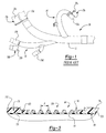
- Duct section 10 includes a body portion 12 and a plurality of branch portions 14.
- Body portion 12 and branch portions 14 are formed with relatively expensive tools and equipment according to a design model.
- the design model typically employs the nominal positions or 3-dimensional location 16 of the components 18 that are to be coupled to the duct section 10, as well as the structure of the device into which duct section 10 is attached, to determine the geometry of the body portion 12 and each of the branch portions 14.
- the design data for the duct section 10 that is developed from the design model is quite complex, with many curves, bends and branch portions 14 being formed in the duct section 10 throughout its length.
- the configuration of the duct section 10 frequently necessitates that it be fabricated in several component parts which are then coupled together via specialized fittings, clamps or welding. Those skilled in the art will readily understand that due to part-to-part variation between the component parts, as well as the variation in which they are assembled, the configuration of duct section 10 can vary widely from the design model. Complicating matters is that the actual positions 20 of the components 18 that are to be coupled to the duct section 10 frequently vary from their nominal position 16.
- One solution that has been proposed is to break the duct section 10 into a plurality of even shorter sub-sections which are coupled together during the installation of duct section 10 into a particular application.
- One drawback of the use of multiple duct sub-sections is that depending on the particular application, it can be difficult to couple the sub-sections together if the duct sub-sections are relatively inaccessible for servicing after they are located into the application.
- This solution is also relatively expensive, can adversely affect the overall reliability of the duct section, increase the frequency with which it must be serviced and add considerable weight to the duct section.
- a duct that is relatively easy and inexpensive to fabricate regardless of the complexity of its configuration.
- the duct should be easy to install and readily accommodate the variation that occurs from part-to-part and application-to-application. Furthermore, the duct should be easily tailored to the unique needs of an application.
- the present invention provides a duct assembly for coupling a pair of components in fluid connection.
- the duct assembly includes a first portion, a second portion and a support collar.
- the second portion is relatively more flexible than the first portion and in fluid connection with the first portion.
- the support collar is coupled to an outer perimeter of the second portion and abuts the first portion.
- the support collar is sized to prevent the formation of a stress riser at an intersection between the first and second portions to thereby render the intersection less susceptible to tearing in response to repeated flexing of the second portion.
- the present invention provides a duct assembly for coupling a pair of components in fluid connection.
- the duct assembly includes a duct portion and a sleeve portion.
- the sleeve portion is bonded to an exterior perimeter of the duct portion in a predetermined area of the duct portion and provides the predetermined area of the duct portion with a predetermined characteristic, such as abrasion and tear resistance.
- the present invention provides a method for forming a reinforced flexible duct assembly.
- the method includes the steps of providing a duct member; determining a diameter of the duct member; selecting a reinforcement member and a reinforcement pitch based on the diameter of the duct member; and bonding the reinforcement member to an exterior surface of the duct member in a helix such that a pitch of the helix is equal to the reinforcement pitch.
- the present invention provides a method for forming a hose assembly for coupling a plurality of components in fluid connection.
- the method includes the steps of forming a rigid duct structure and a flexible duct structure; and bonding the flexible duct structure to an end of the rigid duct structure to produce a clampless flexible joint which permits an end of the flexible duct structure opposite the rigid duct structure to be moved relative to the rigid duct structure.
- the present invention provides a method for forming a hose assembly for coupling a plurality of components in fluid connection.
- the method comprising the steps of forming a flexible duct structure from an elastomeric material; forming first and second rigid duct structures, the first and second rigid duct structures being formed to be relatively more rigid than the flexible duct structure; coupling the first rigid duct structure to a first end of the flexible duct structure; and coupling the second rigid duct structure to a second end of the flexible duct structure such that the flexible duct structure permits the first and second rigid duct structures to be moved relative to one another.
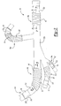
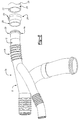
- Duct assembly 50 is shown to include a plurality of rigid duct structures 52, a plurality of flexible duct structures 54 and a plurality of elastomeric attachment sleeves 56.
- Each of the rigid duct structures 52 is formed from a material which is relatively more rigid than the flexible duct structure 54 to which it is adjacent.
- rigid duct structures 52a and 52b are relatively more rigid than flexible duct structure 54a.
- each of the rigid duct structures 52 are fabricated from metals, such as steel and aluminum, plastics and composites such as fiberglass, carbon, KEVLAR® and NEXTEL® .
- Each of the flexible duct structures 54 is positioned between an associated pair of rigid duct structures 52 to permit the shape of duct assembly 50 to be easily tailored to the needs of a particular application.
- the flexible duct structures 54 are illustrated to be bonded to one or more associated rigid duct structures 52 to produce a clampless flexible joint that joins the opposite ends of each of the flexible duct structures 54 to an associated one of the rigid duct structures 52.
- flexible duct structures 54b, 54c and 54d are helix reinforced structures 60 and flexible duct structures 54a and 54e are convoluted bellows structures 62.
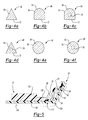
- each of the helix reinforced structures 60 is shown to include an inner liner or member 66, a reinforcing helix 68 and an outer member 70.
- inner member 66 and outer member 70 are formed from conventional elastomeric duct materials (i.e., uncured elastomeric impregnated composite fabrics), such as rubber, silicone, nitrile, butyl, ethylene propylene, neoprene, polyurethane, fluoro silicone and fluoro elastomers and reinforcing helix 68 is fabricated from a thermoplastic material such as polyetherimide, polyphenlsulfone or polyarylsulfone.
- Reinforcing helix 68 is bonded between inner and outer members 66 and 70, thereby reinforcing inner member 66 to guard against bursting, collapsing or kinking.
- the cross-section of reinforcing helix 68 preferably includes a flat base 72 as shown in Figures 4a through 4d but other shapes, such as those shown in Figures 4e and 4f may also be used.
- Reinforcing helix 68 may also have one or more hollow cavities 74 as illustrated in Figures 4c, 4d and 4f to reduce the weight and stiffness of duct assembly 50.
- Helix reinforced structure 60 is otherwise discussed in greater detail in commonly assigned U.S. Patent No. 6,000,435, the disclosure of which is hereby incorporated by reference as if fully set forth herein.
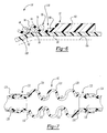
- the inner member 66 of flexible duct structure 54b is positioned to extend into the ends 78 and bonded to the inner walls 80 of rigid duct structures 52b and 52c.
- An adhesive material is applied to the exterior surface 82 of inner member 66 and/or to reinforcing helix 68 and reinforcing helix 68 is applied to the portion of the inner member 66 between rigid duct structures 52b and 52c.
- the size of the material forming reinforcing helix 68 i.e., the reinforcement member 84
- the pitch "p" of reinforcing helix 68 are related to the size of the flexible duct structure 54 in accordance with a second aspect of the present invention as shown, for example, in the table set forth below.
- Sizing reinforcement member 84 and setting the pitch "p" of reinforcing helix 68 to the reinforcement pitch set forth in the table, below permits flexible duct structure 54 to achieve a good balance of strength and flexibility without the need for experimentation to empirically derive the size of the material and pitch of the helix.
- the lay-up also includes a pair of support collars 90 constructed in accordance with a third aspect of the present invention. Support collars 90 are disposed between reinforcing helix 68 and each of the rigid duct structures 52b and 52c and coupled to the exterior surface 94 of the outer member 70.
- Each of the support collars 90 are preferably fabricated from a thermoplastic material such as polyetherimide, polyphenlsulfone or polyarylsulfone.
- the cross-section of the support collars 90 may be solid or hollow and may be identical in configuration to reinforcing helix 68. It is preferred, however, that each of the support collars 90 have a cross-section with a rounded top 96 and a flat base 72, such as the cross-sections shown in Figures 4b and 4c.
- the ends 78 of the rigid duct structures 52 include an end portion 100 which is smaller in diameter than a body portion 102 of the rigid duct structure 52. End portion 100 preferably has a height which is equal to the height of support collar 90 and a length which is equal to the pitch "p" of reinforcing helix 68.
- support collar 90 is operable for distributing loads associated with the movement of flexible duct structure 54 relative to rigid duct structure 52, whether the movement be caused from the bending of flexible duct structure 54 or exposure to a fluid pressure differential.
- the interior 106 of duct assembly 50 is exposed to a pressurized fluid, causing flexible duct structure 54 to bulge in an outward direction.
- Support collar 90 limits the amount by which the wall 108 of flexible duct structure 54 may rotate relative to rigid duct structure 52 and helps to spread the tensile and compressive forces associated with the bulging of the flexible duct structure 54 over a relatively larger area.
- Support collar 90 is therefore sized to prevent the formation of a stress riser at the intersection 110 between rigid duct structure 52 and flexible duct structure 54 to thereby render the intersection 110 less susceptible to tearing or shearing in response to repeated flexing of the flexible duct structure 54.
- FIG. 6 A similar condition is illustrated In Figure 6 wherein the interior 106 of duct assembly 50 is exposed to vacuum pressure, causing flexible duct structure 54 to bulge in an inward direction.
- support collar 90 limits the amount by which the wall 108 of flexible duct structure 54 may rotate relative to rigid duct structure 52 and helps to spread the tensile and compressive forces associated with the bulging of the flexible duct structure 54 over a relatively larger area.
- a similar condition is also experienced by flexible duct structure 54 when flexible duct structure 54 is bent relative to the longitudinal axis of rigid duct structure 52.
- support collar 90 is operable for rendering intersection 110 less susceptible to failures from the deformation of flexible duct structure 54 as a result of a differential fluid pressure as well as rendering intersection 110 less susceptible to failures from the movement or flexure of flexible duct structure 54 relative to rigid duct structure 52.
- each of the convoluted bellows structures 62 is shown to include a plurality of elastomeric convolutions 120, a pair of end portions 122 and a pair of external plies 124.
- Convoluted bellows structure 62 is formed from a suitable elastomer, such as silicone, viton, flourosilicone, nitrile or neoprene.
- the elastomeric material may also be coated or impregnated over a fabric such as fiberglass or kevlar, depending on various design criteria.
- Each of the end portions 122 is illustrated to be generally cylindrical in shape and sized to engage the end sections 128 of the rigid duct structures 52a and 52b.
- External plies 124 may be formed from a material such as fiberglass reinforced silicone and are sized to overlap a portion of one of the end portions 122 and portion of an associated one of the end sections 128, permitting the external plies 124 to secure the convoluted bellows structure 62 to an associated pair of rigid duct structures 52.
- the plurality of elastomeric convolutions 120 couple the end portions 122 together and are resilient enough to permit relative axial movement between rigid duct structures 52a and 52b.
- the convoluted bellows structures 62 are generally employed in relatively short lengths and are generally more flexible than the helix reinforced structures 60. Convoluted bellows structures 62 are typically employed to correct misalignment between the duct assembly 50 and another device (not shown), and/or to permit the length of the duct assembly 50 to be varied and/or to dampen vibrations which are transmitted through duct assembly 50.
- the number, shape and height of the convolutions 120 and length of the convoluted bellows structure 62 is dependent on various design criteria, such as the anticipated misalignment or desired variation in the length of duct assembly 50.
- the fluid (e.g., air) in duct assembly 50 may exert a load on convoluted bellows structure 62 which causes the convolutions 120 to expand outwardly, possibly restricting the flow of fluid through duct assembly 50 and/or permitting the convoluted bellows structure 62 to rub and abrade on another component and in severe cases, rupture.
- a reinforcing material such as a plurality of thermoplastic or metal reinforcing collars 132, may be incorporated into convoluted bellows structure 62 to locally control the expansion of the convolutions 120.
- each of the attachment sleeves 56 is illustrated to be bonded to an associated one of the rigid duct structures 52 and is employed where additional stiffness is required, as for example where the ends 150 of duct assembly 50 are clamped to another device.
- Each of the attachment sleeves 56 is fabricated in a multi-ply manner wherein one or more rigid layers 200 are wrapped around an inner flexible layer 202.
- the rigid layers 200 may be formed from a polyester impregnated fiberglass, for example, and the inner flexible layer 202 may be formed from an elastomeric material such as silicone.
- the silicone inner flexible layer 202 is heat resistant and operable for forming a gasket that contains pressurized fluids within duct assembly 50, while the polyester impregnated fiberglass rigid layers 200 is suitable for withstanding the dynamic loading and motions that are transmitted through attachment sleeve 56.
- duct assembly 50 it is preferred that a lay-up of the entire duct assembly 50 (i.e., the rigid duct structures 52 be coupled to their respective flexible duct structures 54 and attachment sleeves 56) and duct assembly 50 be co-cured in an oven or autoclave in a single cycle.
- each of the flexible duct structures 54 and attachment sleeves 56 may be pre-cured as necessary and subsequently bonded to one or more of the associated rigid duct structures 52.
- Forming duct assembly 50 with flexible duct structures 54 and attachment sleeves 56 is highly advantageous as compared with the duct structures of the prior art because the flexible duct structures 54 permit the rigid duct structures 52 to be fabricated in relatively straight sections, thereby reducing tooling and labor costs associated with the fabrication of duct assembly 50. Furthermore, as flexible duct structures 54 provide a comparatively large degree of latitude in the position of the ends 150 of duct assembly 50, the process of installing duct assembly 50 into an application is considerably easier and faster.
- duct assembly 50a is illustrated to be similar to duct assembly 50 in that it includes a flexible duct structure 54 and a plurality of rigid duct structures 52.
- duct assembly 50a includes a plurality of attachment sleeves 56a which have a beaded end portion 220 that is operable for engaging the inner diameter 222 of a coupling hose 224.
- a retaining ring 226 is slid along the outer surface 228 of coupling hose 224 until it passes over beaded end portion 220.
- retaining ring 226 provides anti-slip resistance to coupling hose 224, preventing coupling hose 224 from detaching from the beaded end portion 220 of hose assembly 50a.
- Pressurized fluid introduced into duct assembly 50a generates a detaching force causing coupling hose 224 and retaining ring 226 to separate from duct assembly 50a until a curved portion 230 of retaining ring 226 makes contact with beaded end portion 220.
- Additional detaching force then acts to squeeze retaining ring 226 and coupling hose 224 against beaded end portion 220, thereby creating a seal between coupling hose 224 and duct assembly 50a.
- Beaded end portion 220 and retaining ring 226 are discussed in greater detail in above-referenced U.S. Patent No. 6,000,435.
- duct assembly 50b is shown to include a duct structure 250 and a sleeve member 252.
- duct structure 250 is a helix reinforced structure 60 constructed in the manner discussed above and not necessarily coupled to a rigid duct structure 52.
- teachings of this aspect of the present invention may be applied to other types of duct structures including rigid duct structures 52. As such, the scope of this aspect of the present invention will not be limited to duct structures having a helix reinforced structure 60.
- Sleeve member 252 includes a hollow central cavity (not specifically shown) which is sized to receive helix reinforced structure 60.
- Sleeve member 252 is slid over duct structure 250 to a predetermined area of helix reinforced structure 60 and bonded to the exterior perimeter 256 of helix reinforced structure 60.
- the ends 258 of sleeve member 252 may be secured to a lay-up of helix reinforced structure 60 via several plies of material 260 that are bonded to sleeve member 252 and helix reinforced structure 60.
- hose assembly 50b is placed in an oven at an elevated temperature to permit the adhesive that bonds helix reinforced structure 60 together as well as adhesive that bonds sleeve member 252 to helix reinforced structure 60 to be simultaneously cured.
- Sleeve member 252 is operable for providing the portion of duct structure 250 to which it is coupled a predetermined one or more predetermined characteristics, such as abrasion resistance, puncture resistance or additional strength. If abrasion resistance is required, sleeve member 252 may be formed from a material such as polyester or KEVLAR® . If puncture resistance or additional strength is required, sleeve member 252 may be formed from a woven material, such as steel wire, carbon graphite or KEVLAR® or from a material such as NEXTEL® . If heat resistance or containment is required, sleeve member 252 may be formed from a material such as NEXTEL® .
- helix reinforced structure 60 is be pre-formed and cured prior to the application of sleeve member 252 to helix reinforced structure 60 and the curing of adhesive 270 which couples sleeve member 252 to helix reinforced structure 60.
- This situation is most likely to arise when duct structure 250 is in need of repair or reworking. In such situations, the repair/rework operation is frequently performed when the duct assembly 50b is partially installed in its operating environment and as such, it is frequently not possible to cure the adhesive in an oven.
- a silicone adhesive such as a room-temperature vulcanizing (RTV) silicone adhesive, may be employed to bond sleeve member 252 to duct structure 250.
- RTV room-temperature vulcanizing
Landscapes
- Engineering & Computer Science (AREA)
- General Engineering & Computer Science (AREA)
- Mechanical Engineering (AREA)
- Rigid Pipes And Flexible Pipes (AREA)
- Joints That Cut Off Fluids, And Hose Joints (AREA)
Applications Claiming Priority (2)
| Application Number | Priority Date | Filing Date | Title |
|---|---|---|---|
| US09/630,902 US6830076B1 (en) | 2000-08-02 | 2000-08-02 | Self-compensating hybrid combination ducts |
| US630902 | 2000-08-02 |
Publications (2)
| Publication Number | Publication Date |
|---|---|
| EP1178254A2 true EP1178254A2 (fr) | 2002-02-06 |
| EP1178254A3 EP1178254A3 (fr) | 2003-07-02 |
Family
ID=24529023
Family Applications (1)
| Application Number | Title | Priority Date | Filing Date |
|---|---|---|---|
| EP01202737A Withdrawn EP1178254A3 (fr) | 2000-08-02 | 2001-07-18 | Ensemble de tuyau flexible |
Country Status (2)
| Country | Link |
|---|---|
| US (1) | US6830076B1 (fr) |
| EP (1) | EP1178254A3 (fr) |
Cited By (1)
| Publication number | Priority date | Publication date | Assignee | Title |
|---|---|---|---|---|
| WO2008090236A1 (fr) * | 2007-01-24 | 2008-07-31 | Venair Iberica, S.A. | Dispositif pour l'absorption des vibrations applicable à des conduites métalliques de processus de fabrication |
Families Citing this family (18)
| Publication number | Priority date | Publication date | Assignee | Title |
|---|---|---|---|---|
| US8776836B2 (en) * | 2001-11-24 | 2014-07-15 | Ragner Technology Corporation | Linearly retractable pressure hose structure |
| US6964352B2 (en) * | 2003-04-23 | 2005-11-15 | Twin Bay Medical, Inc. | Valve for a refrigerator water dispenser |
| US20050224615A1 (en) * | 2004-04-01 | 2005-10-13 | Miller Lisa K | Flexible cable container payout tube |
| US20060091371A1 (en) * | 2004-10-28 | 2006-05-04 | Cox Charles R | CNC impact load deflector sleeve and removable collar for cable and post protection |
| US7878550B2 (en) | 2006-06-30 | 2011-02-01 | The Boeing Company | Apparatus, system, and method for joining and sealing conduits |
| DE102006054268A1 (de) * | 2006-11-17 | 2008-05-21 | Veritas Ag | Rohrförmiges Formteil |
| US9669593B2 (en) * | 2007-06-14 | 2017-06-06 | The Boeing Company | Light weight thermoplastic flex foam and hybrid duct system |
| US8136845B2 (en) * | 2007-12-21 | 2012-03-20 | The Boeing Company | Clamp tension compensating, self-sustaining cuff apparatus and method |
| US8061477B2 (en) * | 2008-08-20 | 2011-11-22 | The Boeing Company | Acoustic management of fluid flow within a duct |
| US20110042939A1 (en) * | 2009-08-24 | 2011-02-24 | Twist, Inc. | Swiveling Preconditioned Air Connector for Aircraft |
| US9909699B2 (en) * | 2011-03-17 | 2018-03-06 | Jay G. Bernhardt | Garden hose with spiral guard |
| US9005730B2 (en) | 2011-11-14 | 2015-04-14 | The Boeing Company | Aircraft interior panels and methods of panel fabrication |
| US10444051B2 (en) | 2017-01-09 | 2019-10-15 | Georg Fischer Signet, LLC | Ultrasonic sensor assembly and method of manufacture |
| US10254143B2 (en) * | 2017-01-13 | 2019-04-09 | Georg Fischer Signet Llc | Fluid-flow sensor assembly having reinforced body |
| US10605453B2 (en) * | 2017-01-24 | 2020-03-31 | Nortiz Corporation | Conduit and hot water supply system |
| US10620060B2 (en) | 2017-07-19 | 2020-04-14 | Georg Fischer Signet, LLC | Combined ultrasonic temperature and conductivity sensor assembly |
| US10302474B2 (en) | 2017-08-09 | 2019-05-28 | Georg Fischer Signet Llc | Insertion ultrasonic sensor assembly |
| US10837579B2 (en) * | 2018-08-31 | 2020-11-17 | Contitech Techno-Chemie Gmbh | Progressive flex geometry for distribution of dynamic forces within a hose bellows |
Citations (1)
| Publication number | Priority date | Publication date | Assignee | Title |
|---|---|---|---|---|
| US6000435A (en) | 1997-12-22 | 1999-12-14 | Mcdonnell Douglas Corporation | Reinforced hose and retainer ring assembly |
Family Cites Families (39)
| Publication number | Priority date | Publication date | Assignee | Title |
|---|---|---|---|---|
| US1579474A (en) * | 1925-08-26 | 1926-04-06 | William H Dempsey | Hose protector |
| US1786585A (en) * | 1927-11-28 | 1930-12-30 | Herbert E Walker | Device for holding looms on cables |
| US2185741A (en) * | 1938-07-05 | 1940-01-02 | Lloyd F Sorg | Hose attachment |
| US2700988A (en) * | 1951-06-27 | 1955-02-01 | Aeroquip Corp | Hose fitting |
| US3050087A (en) * | 1957-03-22 | 1962-08-21 | Porter Co Inc H K | Flexible hose |
| US3076737A (en) * | 1957-11-15 | 1963-02-05 | Fred T Roberts & Company | Corrugated annularly reinforced hose and method for its manufacture |
| US3060069A (en) * | 1959-10-23 | 1962-10-23 | Fred E Sindars | Insulating jacket for fluid lines and the like |
| US3135295A (en) * | 1961-11-09 | 1964-06-02 | Eugene H Ziebold | Bellows expansion unit utilizing support rings |
| FR1359919A (fr) * | 1963-03-22 | 1964-04-30 | Renault | Raccord de jonction pour tuyaux en matière plastique |
| DE1604418A1 (de) * | 1966-11-25 | 1970-09-10 | Merkel Asbest & Gummiwerke | Faltenbalg aus Kunststoff mit Metallummantelung |
| US3626988A (en) * | 1969-11-12 | 1971-12-14 | Resistoflex Corp | Unbonded cloth reinforced bellows and method of manufacture |
| US4098298A (en) * | 1973-12-14 | 1978-07-04 | Herbert Vohrer | Hose |
| DE2402524A1 (de) * | 1974-01-19 | 1975-07-31 | Kloeckner Humboldt Deutz Ag | Wellrohr |
| US4001918A (en) * | 1974-12-09 | 1977-01-11 | Stratoflex, Inc. | Guard retainer |
| GB1499769A (en) | 1975-05-14 | 1978-02-01 | Wood C | Flexible duct |
| US4033381A (en) | 1975-06-27 | 1977-07-05 | General Connectors Corporation | Hot air duct |
| US3992505A (en) * | 1975-08-18 | 1976-11-16 | The Gates Rubber Company | Method for producing curved elastomeric tubular articles |
| US4327776A (en) | 1975-11-10 | 1982-05-04 | Manville Service Corporation | Thin-walled metal duct having integral reinforced coupling ends |
| US4086665A (en) * | 1976-12-16 | 1978-05-02 | Thermo Electron Corporation | Artificial blood conduit |
| US4196031A (en) * | 1978-03-10 | 1980-04-01 | Titeflex Corporation | Method of making a preformed semirigid plastic hose wrapped with a wire spiral |
| CA1147272A (fr) | 1979-05-01 | 1983-05-31 | Rudolf J. Maas | Methode pour la separation du para-xylene |
| US4295496A (en) * | 1980-02-19 | 1981-10-20 | The Gates Rubber Company | Hose with internal insert member |
| US4615359A (en) | 1982-08-30 | 1986-10-07 | Affa Stephen N | Shroud for aircraft duct |
| US4564222A (en) | 1984-08-27 | 1986-01-14 | Hydrasearch Co., Inc. | Separable coupling for thin-walled flexible hose |
| US5388870A (en) | 1987-06-23 | 1995-02-14 | Proprietary Technology, Inc. | Apparatus for and method of attaching hoses and tubes to a fitting |
| US4966202A (en) * | 1988-11-14 | 1990-10-30 | Dayco Products, Inc. | Shape retention hose construction |
| JPH02179213A (ja) | 1988-12-27 | 1990-07-12 | Shiro Kanao | 耐圧螺旋波形管 |
| US5062457A (en) * | 1989-05-05 | 1991-11-05 | Mcdonnell Douglas Corporation | Corrugated air hose assembly |
| US5143409A (en) * | 1989-08-30 | 1992-09-01 | Titeflex Corporation | Stress relief device |
| US5031982A (en) | 1990-05-23 | 1991-07-16 | Hughes Aircraft Company | Flexible payout duct |
| US5112088A (en) | 1990-10-10 | 1992-05-12 | Stainless Steel Products, Inc. | Duct joint link assembly |
| US5469892A (en) * | 1992-04-14 | 1995-11-28 | Itt Automotive, Inc. | Corrugated polymeric tubing having at least three layers with at least two respective layers composed of polymeric materials dissimilar to one another |
| DE9319879U1 (de) * | 1993-12-23 | 1994-03-17 | Ems-Inventa AG, Zürich | Sequentiell Coextrudierte Kühlflüssigkeitsleitung |
| US5466230A (en) * | 1994-06-09 | 1995-11-14 | Cordis Corporation | Catheter sheath introducer with strain relief |
| DE19632756C2 (de) * | 1996-08-14 | 2002-02-07 | Stenflex Rudolf Stender Gmbh | Einrichtung zum Ausgleich der Bewegung zweier miteinander verbundener Rohre mit wenigstens zweilagig ausgebildetem Balgkörper |
| US6050300A (en) | 1998-09-11 | 2000-04-18 | Karl Weiss Hoch-Tief - Und Rohrleitungsbau Gmbh & Co. | Method and an apparatus for lining a pipe or duct |
| US20030075228A1 (en) * | 2000-06-22 | 2003-04-24 | Tippett Stephen W. | Flexible duct and its method of fabrication |
| US20020179169A1 (en) * | 2001-06-04 | 2002-12-05 | Shanfelt Donald Y. | Disposable sewer hose |
| US6769452B2 (en) * | 2001-11-20 | 2004-08-03 | Dqp, Llc | Leak-free flexible conduit |
-
2000
- 2000-08-02 US US09/630,902 patent/US6830076B1/en not_active Expired - Lifetime
-
2001
- 2001-07-18 EP EP01202737A patent/EP1178254A3/fr not_active Withdrawn
Patent Citations (1)
| Publication number | Priority date | Publication date | Assignee | Title |
|---|---|---|---|---|
| US6000435A (en) | 1997-12-22 | 1999-12-14 | Mcdonnell Douglas Corporation | Reinforced hose and retainer ring assembly |
Cited By (1)
| Publication number | Priority date | Publication date | Assignee | Title |
|---|---|---|---|---|
| WO2008090236A1 (fr) * | 2007-01-24 | 2008-07-31 | Venair Iberica, S.A. | Dispositif pour l'absorption des vibrations applicable à des conduites métalliques de processus de fabrication |
Also Published As
| Publication number | Publication date |
|---|---|
| US6830076B1 (en) | 2004-12-14 |
| EP1178254A3 (fr) | 2003-07-02 |
Similar Documents
| Publication | Publication Date | Title |
|---|---|---|
| US6830076B1 (en) | Self-compensating hybrid combination ducts | |
| US6196763B1 (en) | Connection system for hoses, expansion joints and actuators | |
| US20220356900A1 (en) | Composite drive shafts | |
| EP2041465B1 (fr) | Appareil, système et procédé de raccordement et d'étanchéification de conduits | |
| JP5236936B2 (ja) | 可撓性管継手 | |
| US7347456B2 (en) | Sleeve for joining and sealing conduits | |
| JP4367734B2 (ja) | 管路の内張り材 | |
| US8157469B2 (en) | Composite structural member and method for producing the same | |
| JP4964706B2 (ja) | 管継手 | |
| US4518018A (en) | Reinforced formed hose | |
| US4240653A (en) | Flexible expansion joint | |
| JP2001159478A (ja) | 可とう伸縮管及び可とう伸縮継手 | |
| JP2009036225A (ja) | 管継手 | |
| WO1997018408A2 (fr) | Construction de soufflet en sandwich | |
| WO2014003545A1 (fr) | Brides intégralement renforcées | |
| JP7712541B2 (ja) | 配管継手 | |
| JP3981419B2 (ja) | 埋設可撓継手およびその製造方法 | |
| JP2005001335A (ja) | 外形波形状の可撓管の製造方法 | |
| EP4345326A1 (fr) | Arbre d'entraînement composite flexible | |
| JP3651692B2 (ja) | 異径ゴム配管継手及びその製造方法 | |
| WO2010101872A1 (fr) | Procédé de fabrication d'un tube fluoropolymère pourvu d'un habillage | |
| JP3842853B2 (ja) | 地震対応型偏心ホ−スおよびその製造方法 | |
| JP2024084596A (ja) | 流体圧アクチュエータ | |
| GB2413976A (en) | Manufacture of pipes | |
| JPS6334391A (ja) | エラストマ−ホ−ス用網目付ニップルとその製造方法 |
Legal Events
| Date | Code | Title | Description |
|---|---|---|---|
| PUAI | Public reference made under article 153(3) epc to a published international application that has entered the european phase |
Free format text: ORIGINAL CODE: 0009012 |
|
| AK | Designated contracting states |
Kind code of ref document: A2 Designated state(s): AT BE CH CY DE DK ES FI FR GB GR IE IT LI LU MC NL PT SE TR |
|
| AX | Request for extension of the european patent |
Free format text: AL;LT;LV;MK;RO;SI |
|
| PUAL | Search report despatched |
Free format text: ORIGINAL CODE: 0009013 |
|
| AK | Designated contracting states |
Designated state(s): AT BE CH CY DE DK ES FI FR GB GR IE IT LI LU MC NL PT SE TR |
|
| AX | Request for extension of the european patent |
Extension state: AL LT LV MK RO SI |
|
| AKX | Designation fees paid | ||
| REG | Reference to a national code |
Ref country code: DE Ref legal event code: 8566 |
|
| STAA | Information on the status of an ep patent application or granted ep patent |
Free format text: STATUS: THE APPLICATION IS DEEMED TO BE WITHDRAWN |
|
| 18D | Application deemed to be withdrawn |
Effective date: 20040201 |