EP1178275A2 - Spülkammer - Google Patents
Spülkammer Download PDFInfo
- Publication number
- EP1178275A2 EP1178275A2 EP01115689A EP01115689A EP1178275A2 EP 1178275 A2 EP1178275 A2 EP 1178275A2 EP 01115689 A EP01115689 A EP 01115689A EP 01115689 A EP01115689 A EP 01115689A EP 1178275 A2 EP1178275 A2 EP 1178275A2
- Authority
- EP
- European Patent Office
- Prior art keywords
- purge
- gases
- purge chamber
- chamber according
- materials
- Prior art date
- Legal status (The legal status is an assumption and is not a legal conclusion. Google has not performed a legal analysis and makes no representation as to the accuracy of the status listed.)
- Withdrawn
Links
Images
Classifications
-
- F—MECHANICAL ENGINEERING; LIGHTING; HEATING; WEAPONS; BLASTING
- F27—FURNACES; KILNS; OVENS; RETORTS
- F27B—FURNACES, KILNS, OVENS OR RETORTS IN GENERAL; OPEN SINTERING OR LIKE APPARATUS
- F27B9/00—Furnaces through which the charge is moved mechanically, e.g. of tunnel type; Similar furnaces in which the charge moves by gravity
- F27B9/06—Furnaces through which the charge is moved mechanically, e.g. of tunnel type; Similar furnaces in which the charge moves by gravity heated without contact between combustion gases and charge; electrically heated
- F27B9/10—Furnaces through which the charge is moved mechanically, e.g. of tunnel type; Similar furnaces in which the charge moves by gravity heated without contact between combustion gases and charge; electrically heated heated by hot air or gas
-
- F—MECHANICAL ENGINEERING; LIGHTING; HEATING; WEAPONS; BLASTING
- F24—HEATING; RANGES; VENTILATING
- F24F—AIR-CONDITIONING; AIR-HUMIDIFICATION; VENTILATION; USE OF AIR CURRENTS FOR SCREENING
- F24F9/00—Use of air currents for screening, e.g. air curtains
-
- F—MECHANICAL ENGINEERING; LIGHTING; HEATING; WEAPONS; BLASTING
- F27—FURNACES; KILNS; OVENS; RETORTS
- F27B—FURNACES, KILNS, OVENS OR RETORTS IN GENERAL; OPEN SINTERING OR LIKE APPARATUS
- F27B9/00—Furnaces through which the charge is moved mechanically, e.g. of tunnel type; Similar furnaces in which the charge moves by gravity
- F27B9/30—Details, accessories or equipment specially adapted for furnaces of these types
- F27B9/3005—Details, accessories or equipment specially adapted for furnaces of these types arrangements for circulating gases
- F27B9/3011—Details, accessories or equipment specially adapted for furnaces of these types arrangements for circulating gases arrangements for circulating gases transversally
-
- F—MECHANICAL ENGINEERING; LIGHTING; HEATING; WEAPONS; BLASTING
- F24—HEATING; RANGES; VENTILATING
- F24F—AIR-CONDITIONING; AIR-HUMIDIFICATION; VENTILATION; USE OF AIR CURRENTS FOR SCREENING
- F24F11/00—Control or safety arrangements
- F24F11/0001—Control or safety arrangements for ventilation
- F24F2011/0002—Control or safety arrangements for ventilation for admittance of outside air
- F24F2011/0004—Control or safety arrangements for ventilation for admittance of outside air to create overpressure in a room
-
- F—MECHANICAL ENGINEERING; LIGHTING; HEATING; WEAPONS; BLASTING
- F27—FURNACES; KILNS; OVENS; RETORTS
- F27D—DETAILS OR ACCESSORIES OF FURNACES, KILNS, OVENS OR RETORTS, IN SO FAR AS THEY ARE OF KINDS OCCURRING IN MORE THAN ONE KIND OF FURNACE
- F27D1/00—Casings; Linings; Walls; Roofs
- F27D1/18—Door frames; Doors, lids or removable covers
- F27D1/1858—Doors
- F27D2001/1875—Hanging doors and walls
Definitions
- This invention relates to a purge chamber according to the features of claim 1.
- U.S. Patent 4,992,044 discloses a furnace for high temperature treatment of semiconductor wafers utilizing a scavenger arrangement for controlling gas flow.
- U.S. Patent 5,118,286 discloses a method and an apparatus for controlling gas flow patterns and avoiding the mixing of spent reactant gases with ambient air in the treatment of semiconductor wafers.
- U.S. Patent 5,645,417 discloses a thermal treatment of silicon wafers in a thermal processing furnace tube wherein the inner surface has a plurality of dimples thereon to promote a more turbulent flow of gases and a more uniform reaction across the surface of the wafers.
- the above and other objects are achieved in accordance with the present invention, which comprises a purge chamber for providing a controlled gaseous atmosphere for the treatment of materials.
- the purge chamber comprises a housing having an entrance end and an exit end, means for conveying materials therethrough, gas inlets and outlets, and internal gas barriers to provide a controlled flow of gases within the housing.
- a first gas barrier and a second gas barrier may be positioned respectively near the entrance end and the exit end to inhibit the entry of unwanted gases and to define a purge region having a controlled flow of gases therethrough.
- the gas barriers are flexible physical barriers, preferably extending across the full width of the purge chamber and suspended from the upper portion of thereof. The gas barriers are flexible to allow the passage of material being conveyed through the chamber.
- the gas barriers are in the form of flapper doors, spanning the width of the chamber and hingedly suspended from a supporting rack near the top of the purge chamber.
- the door may be pushed up by the moving materials allowing the materials to pass.
- the gas barriers may be in the form of flexible strips, for example, plastic strips, or chains, or thin strips of metal foil, or the like.
- the strips may be arranged in multiple staggered rows and suspended from the upper region of the chamber, and sufficiently flexible to be pushed aside by the materials passing through and able to return to their original vertical orientation after the materials have passed.
- the gas barrier at the entry end and the exit end of the purge region aid in the maintenance of a slight positive pressure therein.
- additional gas barriers may be present to further control the flow of purge gases and define additional purge regions within the purge chamber.
- the gas barriers that is, flapper doors, flexible strips, or the like, are suspended from a removable frame mounted at the top of the purge chamber, so that the number and location of the doors, or gas barriers, can be conveniently modified to adjust to various process requirements.
- the frame may be supported on tracks or on hangers located in the upper portion of the interior of the purge chamber.
- At least one purge gas inlet and at least one purge gas outlet are Positioned within the purge region, that is between the first and second gas barriers, to provide a cross-flow of selected gases to purge and replace the gases within the purge region.
- positive pressure gas inlets are preferably positioned adjacent to the first and second gas barriers to provide a positive pressure at each end and act as a barrier to entry of unwanted gases from outside of the purge region.
- the purge chamber of this invention may be operated as a batch unit for the gaseous treatment of materials.
- the purge chamber is provided with a means for conveying materials being treated through the chamber in a continuous fashion.
- the purge chamber may be of various sizes and shapes, the preferred shape being of rectangular cross-section with a height substantially less than the width, to enhance the cross-flow of gas.
- the length may vary considerably. In general, the longer the chamber, the more complete the gas purging that will take place.
- the purge chamber may be operated as a "stand alone" unit for the gaseous treatment of materials or as an appendage or attachment unit for a furnace or other apparatus.
- the entrance end and the exit end have means such as flanges for attachment to a furnace either at the entrance of the furnace, for a pre-treatment of the materials to be processed, or at the exit end of the furnace for a post-treatment, or both.
- the transport means e. g. moving belt, etc. may be cooperatively connected to transport mechanism within the furnace for continuous transport of the materials through the chamber and through the furnace.
- the purge chamber may be operated at various temperatures.
- the operating temperature will typically be between about room temperature and about 200° C.
- Various materials of construction may be employed, including for example, steel, graphite, plastic or the like, depending on the temperature and other process conditions to be applied.
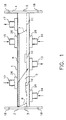
- the purge chamber of the present invention includes a housing 1 having a flange 2 at entry end 3 and flange 4 at exit end 5. Within the chamber, flapper door 6, near entry end 3, and flapper door 7, near exit end 5, are hingedly suspended from supporting rack 8.
- the flapper doors define a purge region 9 wherein the gaseous environment is controlled.
- a cross-flow of purge gas may enter through inlet 12 and exit through outlet 13.
- a positive pressure inlet 14 provides a positive pressure in the region near entry 3 to inhibit the entry of unwanted air or other gases. The gas entering through inlet 14 may exit through outlet 13 and through flapper door 6 and entry 3.
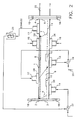
- Inlet 15 and inlet 16 provide for the entry of gases to create a positive pressure near the exit end 5 to inhibit the entry of unwanted gases through the exit end 5. Gases entering through inlets 15 and 16 may exit primarily through outlet 17 as well as exit 5 and will serve to create a positive pressure within the purge region 9 at flapper door 7. When the purge chamber is attached to the entrance of a furnace (Fig. 2), outlet 17 will further serve to exhaust any unwanted gases that may enter through exit 5 from the furnace.
- the inlets such as inlets 12, 14, 15, and 16 may be provided with inner surfaces having multiple rows of precision cut slots 26 through which entering gases are passed to evenly distribute the gas across the chamber and sized to increase flow velocities to improve purging efficiencies.
- Slots 26 may be arranged in various patterns or configurations such as staggered parallel rows or in an angled herringbone configuration and may be positioned within the gas inlet or as a part of purge chamber housing.
- the purge chamber of this invention may be operated independently as a chamber for the gaseous treatment of material, or may be operated cooperatively with a furnace or other unit for further treatment of the materials. It may, for example, be attached to the entrance of a kiln or furnace for pretreatment of materials to be further heat treated, or at the exit of such a furnace or kiln for a gaseous post treatment of materials that have been passed through the kiln or furnace. In such case, conveyor means 11 may be continuous within the purge chamber(s) and the furnace. Various attachment means may be used, including flanges, such as flanges 2 and 4 by means of bolts through bolt holes 18.
- a furnace treatment may involve treatment with gases that might tend to expand into the purge chamber through exit end 5 and contaminate the atmosphere within the purge chamber. Such gases may be exhausted through exhaust outlet 17.
- the purge chamber of the present invention may include means for recycling the gases employed in the purge chamber treatment as well as gases from an attached furnace.
- purge gases entering the chamber through inlet 12 through line 20 may first be routed through eductor 19 to combine with all or a portion of the gases exiting from outlet 13. Exiting gases may be treated if necessary before being recycled.
- the gaseous treatment in the purge chamber is used to remove moisture from the atmosphere, the exiting gases may be dried by passing through a condenser 21, or other moisture removing treatment before being recycled to the purge chamber.
- gases entering from an attached furnace, such as furnace 25, may be similarly and recycled into the purge chamber.
- furnace treatment of some electronic components may require heating in a humidified atmosphere and a portion of the humidified gas from attached furnace 25 may enter the purge chamber through exit 5.
- such humidified gases may be exhausted through outlet 17 and passed through condenser 21 before being recycled through eductor 22 to inlet 14.
Landscapes
- Engineering & Computer Science (AREA)
- Mechanical Engineering (AREA)
- General Engineering & Computer Science (AREA)
- Chemical & Material Sciences (AREA)
- Combustion & Propulsion (AREA)
- Furnace Details (AREA)
- Furnace Charging Or Discharging (AREA)
- Waste-Gas Treatment And Other Accessory Devices For Furnaces (AREA)
- Treating Waste Gases (AREA)
- Tunnel Furnaces (AREA)
- Cleaning In General (AREA)
Applications Claiming Priority (2)
| Application Number | Priority Date | Filing Date | Title |
|---|---|---|---|
| US632880 | 1990-12-24 | ||
| US09/632,880 US6328558B1 (en) | 2000-08-04 | 2000-08-04 | Purge chamber |
Publications (2)
| Publication Number | Publication Date |
|---|---|
| EP1178275A2 true EP1178275A2 (de) | 2002-02-06 |
| EP1178275A3 EP1178275A3 (de) | 2003-12-03 |
Family
ID=24537335
Family Applications (1)
| Application Number | Title | Priority Date | Filing Date |
|---|---|---|---|
| EP01115689A Withdrawn EP1178275A3 (de) | 2000-08-04 | 2001-07-05 | Spülkammer |
Country Status (6)
| Country | Link |
|---|---|
| US (1) | US6328558B1 (de) |
| EP (1) | EP1178275A3 (de) |
| JP (1) | JP2002090072A (de) |
| KR (1) | KR20020012117A (de) |
| CN (1) | CN1337558A (de) |
| TW (1) | TW509772B (de) |
Families Citing this family (3)
| Publication number | Priority date | Publication date | Assignee | Title |
|---|---|---|---|---|
| US7514650B2 (en) * | 2005-12-08 | 2009-04-07 | Despatch Industries Limited Partnership | Continuous infrared furnace |
| JP4589942B2 (ja) * | 2007-05-29 | 2010-12-01 | エスペック株式会社 | 気体処理ユニット |
| WO2009117693A2 (en) * | 2008-03-21 | 2009-09-24 | Brooks Automation, Inc. | Method of reclaiming and storing a valuable process gas |
Family Cites Families (5)
| Publication number | Priority date | Publication date | Assignee | Title |
|---|---|---|---|---|
| US3778221A (en) * | 1969-02-26 | 1973-12-11 | Allegheny Ludlum Ind Inc | Annealing furnace and method for its operation |
| US4238122A (en) * | 1979-03-12 | 1980-12-09 | Allegheny Ludlum Steel Corporation | Apparatus for annealing steel |
| US4397451A (en) * | 1981-06-10 | 1983-08-09 | Chugai Ro Kogyo Co., Ltd. | Furnace for the heat treatment of scale-covered steel |
| JPS6127485A (ja) * | 1984-07-17 | 1986-02-06 | 中外炉工業株式会社 | 連続式雰囲気熱処理炉 |
| JPH11186363A (ja) * | 1997-12-24 | 1999-07-09 | Shin Etsu Handotai Co Ltd | 半導体製造装置 |
-
2000
- 2000-08-04 US US09/632,880 patent/US6328558B1/en not_active Expired - Lifetime
-
2001
- 2001-07-05 EP EP01115689A patent/EP1178275A3/de not_active Withdrawn
- 2001-07-09 CN CN01122832A patent/CN1337558A/zh active Pending
- 2001-07-11 JP JP2001211110A patent/JP2002090072A/ja active Pending
- 2001-07-12 KR KR1020010042128A patent/KR20020012117A/ko not_active Abandoned
- 2001-07-16 TW TW090117371A patent/TW509772B/zh not_active IP Right Cessation
Also Published As
| Publication number | Publication date |
|---|---|
| CN1337558A (zh) | 2002-02-27 |
| US6328558B1 (en) | 2001-12-11 |
| KR20020012117A (ko) | 2002-02-15 |
| JP2002090072A (ja) | 2002-03-27 |
| TW509772B (en) | 2002-11-11 |
| EP1178275A3 (de) | 2003-12-03 |
Similar Documents
| Publication | Publication Date | Title |
|---|---|---|
| RU2116600C1 (ru) | Охладитель для охлаждения материала, состоящего из макрочастиц | |
| US6267587B1 (en) | Thermal curing oven and thermal curing process | |
| CA1067692A (en) | Oven for a procession of containers | |
| EP0980642B9 (de) | Verfahren und vorrichtung zum behandeln von plattenförmigem gut, insbesondere von leiterplatten | |
| US11035016B2 (en) | System and method for improving quench air flow | |
| CN101874188A (zh) | 用于对产品进行热处理的隧道窑 | |
| JPH03125897A (ja) | 酸素濃度極低下雰囲気炉 | |
| KR20080032092A (ko) | 개선된 유동 조건을 이용한, 결합제의 연속 촉매적 제거를위한 장치 및 방법 | |
| US6328558B1 (en) | Purge chamber | |
| KR101430566B1 (ko) | 컨베이어 시스템, 복합 시스템 및 금속 야금학적 방법의결합 방법 | |
| ITMI981984A1 (it) | Dispositivo per il trattamento termico di pezzi | |
| US4285668A (en) | Pressurized gas seal for furnace atmosphere containment | |
| HK1041042A1 (en) | Continuous pusher furnace having traveling gas barrier | |
| JP5075827B2 (ja) | コンディショニングされた空気流により、細長い食品を処理するための装置 | |
| JP7065240B1 (ja) | 連続加熱炉およびそれを用いた被処理物の加熱処理方法 | |
| US5800774A (en) | Heat treating furnace and method | |
| US3957479A (en) | Glass treating furnace | |
| US3930831A (en) | Furnace for heat treating glass sheet material | |
| EP3444547B1 (de) | Lebensmittelgefrieranlage und zugehöriges verfahren zur abfuhr von gefriergas | |
| JPH0136906Y2 (de) | ||
| RU2082701C1 (ru) | Способ термовлажностной обработки, преимущественно блочных бетонных изделий | |
| JP3060572B2 (ja) | 連続式加熱装置 | |
| JPH06273070A (ja) | 連続炉における炉内冷却構造 | |
| JPH03249118A (ja) | 鋼材の熱処理炉 | |
| JPH03249120A (ja) | 鋼材の熱処理炉 |
Legal Events
| Date | Code | Title | Description |
|---|---|---|---|
| PUAI | Public reference made under article 153(3) epc to a published international application that has entered the european phase |
Free format text: ORIGINAL CODE: 0009012 |
|
| 17P | Request for examination filed |
Effective date: 20010712 |
|
| AK | Designated contracting states |
Kind code of ref document: A2 Designated state(s): AT BE CH CY DE DK ES FI FR GB GR IE IT LI LU MC NL PT SE TR |
|
| AX | Request for extension of the european patent |
Free format text: AL;LT;LV;MK;RO;SI |
|
| PUAL | Search report despatched |
Free format text: ORIGINAL CODE: 0009013 |
|
| AK | Designated contracting states |
Kind code of ref document: A3 Designated state(s): AT BE CH CY DE DK ES FI FR GB GR IE IT LI LU MC NL PT SE TR |
|
| AX | Request for extension of the european patent |
Extension state: AL LT LV MK RO SI |
|
| RIC1 | Information provided on ipc code assigned before grant |
Ipc: 7F 24F 9/00 B Ipc: 7F 27B 9/10 B Ipc: 7H 01L 21/00 B Ipc: 7C 30B 25/14 B Ipc: 7F 27D 7/00 A |
|
| STAA | Information on the status of an ep patent application or granted ep patent |
Free format text: STATUS: THE APPLICATION IS DEEMED TO BE WITHDRAWN |
|
| 18D | Application deemed to be withdrawn |
Effective date: 20040203 |