EP1178337A2 - Dispositif de fabrication d'un réseau dans une fibre à longue période insensible à la polarisation - Google Patents
Dispositif de fabrication d'un réseau dans une fibre à longue période insensible à la polarisation Download PDFInfo
- Publication number
- EP1178337A2 EP1178337A2 EP01117469A EP01117469A EP1178337A2 EP 1178337 A2 EP1178337 A2 EP 1178337A2 EP 01117469 A EP01117469 A EP 01117469A EP 01117469 A EP01117469 A EP 01117469A EP 1178337 A2 EP1178337 A2 EP 1178337A2
- Authority
- EP
- European Patent Office
- Prior art keywords
- fiber
- laser beam
- ultraviolet laser
- ultraviolet
- long period
- Prior art date
- Legal status (The legal status is an assumption and is not a legal conclusion. Google has not performed a legal analysis and makes no representation as to the accuracy of the status listed.)
- Withdrawn
Links
Images



Classifications
-
- G—PHYSICS
- G02—OPTICS
- G02B—OPTICAL ELEMENTS, SYSTEMS OR APPARATUS
- G02B6/00—Light guides; Structural details of arrangements comprising light guides and other optical elements, e.g. couplings
- G02B6/02—Optical fibres with cladding with or without a coating
- G02B6/02057—Optical fibres with cladding with or without a coating comprising gratings
- G02B6/02076—Refractive index modulation gratings, e.g. Bragg gratings
- G02B6/0208—Refractive index modulation gratings, e.g. Bragg gratings characterised by their structure, wavelength response
- G02B6/021—Refractive index modulation gratings, e.g. Bragg gratings characterised by their structure, wavelength response characterised by the core or cladding or coating, e.g. materials, radial refractive index profiles, cladding shape
- G02B6/02109—Refractive index modulation gratings, e.g. Bragg gratings characterised by their structure, wavelength response characterised by the core or cladding or coating, e.g. materials, radial refractive index profiles, cladding shape having polarization sensitive features, e.g. reduced photo-induced birefringence
-
- G—PHYSICS
- G02—OPTICS
- G02B—OPTICAL ELEMENTS, SYSTEMS OR APPARATUS
- G02B6/00—Light guides; Structural details of arrangements comprising light guides and other optical elements, e.g. couplings
- G02B6/02—Optical fibres with cladding with or without a coating
- G02B6/02057—Optical fibres with cladding with or without a coating comprising gratings
- G02B6/02076—Refractive index modulation gratings, e.g. Bragg gratings
- G02B6/02123—Refractive index modulation gratings, e.g. Bragg gratings characterised by the method of manufacture of the grating
- G02B6/02142—Refractive index modulation gratings, e.g. Bragg gratings characterised by the method of manufacture of the grating based on illuminating or irradiating an amplitude mask, i.e. a mask having a repetitive intensity modulating pattern
-
- G—PHYSICS
- G02—OPTICS
- G02B—OPTICAL ELEMENTS, SYSTEMS OR APPARATUS
- G02B6/00—Light guides; Structural details of arrangements comprising light guides and other optical elements, e.g. couplings
- G02B6/02—Optical fibres with cladding with or without a coating
- G02B6/02057—Optical fibres with cladding with or without a coating comprising gratings
- G02B6/02076—Refractive index modulation gratings, e.g. Bragg gratings
- G02B6/0208—Refractive index modulation gratings, e.g. Bragg gratings characterised by their structure, wavelength response
- G02B6/02085—Refractive index modulation gratings, e.g. Bragg gratings characterised by their structure, wavelength response characterised by the grating profile, e.g. chirped, apodised, tilted, helical
- G02B6/02095—Long period gratings, i.e. transmission gratings coupling light between core and cladding modes
Definitions
- the present invention relates generally to an optical communication, and in particular to a device for fabricating a long period fiber grating for the optical communication.
- a long period fiber grating composing an optical transmission system couples optical signals having a specific wavelength band in a cladding mode in the fiber, and passes optical signals having a different wavelength band.
- the long period fiber grating has been used as a fiber filter such as a non-reflecting band rejection filter and band-pass filter, an optical sensor, and a gain flattener for erbium-doped amplifier.
- a method for fabricating the long period fiber grating is based on the principle that 'germanium-doped optical fiber is photosensitive to ultraviolet light' in pp.647-649 of APPL. PHYS. Lett. Vol. 32, 'Photosensitivity in optical fiber wave guides : Application to reflection filter fabrication' suggested by K. O. Hill et. al. and published in 1978.
- the representative method for fabricating the long period fiber grating is ultraviolet irradiation using 'side writing' in pp.823-825 of Opt. Lett. Vol. 14, 'Formation of Bragg gratings in optical fibers by transverse holographic method' suggested by G. Meltz et. al. and published in 1989.
- FIG. 1 is a structure diagram illustrating a conventional device for fabricating a long period fiber grating.
- the conventional device 100 for fabricating the long period fiber grating includes a ultraviolet laser 110 for irradiating a ultraviolet laser beam, a lens 120 for adjusting a focus of the ultraviolet laser beam irradiated from the ultraviolet laser 110, an amplitude mask 130 for selectively passing the ultraviolet laser beam from the lens 120, and a fixing unit 140 for fixing both ends of a fiber (f) where the long period grating is formed by the ultraviolet laser beam from the amplitude mask 130.
- the ultraviolet laser beam is asymmetrically irradiated on one side of the fiber, and a refractive index of the core of the fiber is anisotropically varied due to a polarization status of the ultraviolet laser beam, to cause birefringence in the fiber.
- the birefringence due to the polarization of the ultraviolet laser beam has been disclosed in detail in a treatise of T. Since, p.2100 to p.2105 of 'Journal of the optical society of America B' in 1994.
- the long period fiber grating requires more variations of the refractive index than the fiber Bragg grating by 10 times, and thus has serious variations of the refractive index due to the polarization status of the ultraviolet laser beam, namely high polarization dependence.
- the polarization dependence of the long period fiber grating results in PDL (Polarization Dependent Loss) and PMD (Polarization Mode Dispersion), thereby deteriorating a property of the long period fiber grating as an optical communication device.
- an object of the present invention to provide a device for fabricating a polarization insensitive long period fiber grating which can reduce a property loss due to birefringence resulting from a polarization status of a ultraviolet laser beam.
- a device having the features of claim 1.
- a mirror for reflecting the ultraviolet laser beam from the amplitude mask to the outer circumferential surface of the fiber. This can reduce a property loss due to birefringence generated when ultraviolet light is irradiated merely to one side of a fiber.
- FIG. 2 is a structure diagram illustrating a device for fabricating a polarization insensitive long period fiber grating in accordance with a first embodiment of the present invention.
- the device 200 for fabricating the polarization insensitive long period fiber grating includes a ultraviolet laser 210 for irradiating a ultraviolet laser beam, a ultraviolet polarizer 220 for converting a polarization status of the ultraviolet laser beam into a linear polarization status in parallel to a longitudinal direction of a fiber (f), a lens 230 for adjusting a focus of the ultraviolet laser beam from the ultraviolet polarizer 220, an amplitude mask 240 for selectively passing the ultraviolet laser beam from the lens 230, and a mount 250 having a pair of fixing units 250a, 250b for fixing both ends of the fiber (f), so that the outer circumferential surface of the fiber (f) can be exposed to the ultraviolet laser beam from the amplitude mask 240.
- the polarization status of the ultraviolet laser beam irradiated to generate variations of a refractive index of the fiber is the linear polarization status vertical to the longitudinal direction of the fiber
- the birefringence is remarkably increased in the fiber.
- the polarization status of the ultraviolet laser beam is the linear polarization status in parallel to the longitudinal direction of the fiber, the birefringence is decreased.
- the ultraviolet polarizer 220 converts the polarization status of the ultraviolet laser beam irradiated from the ultraviolet laser 210 into the linear polarization status in parallel to the longitudinal direction of the fiber (f).
- the ultraviolet laser beam from the ultraviolet polarizer 220 is irradiated on the fiber in the linear polarization status, to reduce the birefringence in an axial direction of the fiber (f).
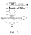
- FIG. 3 is a structure diagram illustrating a device for fabricating a polarization insensitive long period fiber grating in accordance with a second embodiment of the present invention.
- the device 300 for fabricating the polarization insensitive long period fiber grating includes a ultraviolet laser 310 for irradiating a ultraviolet laser beam, a ultraviolet polarizer 320 for converting a polarization status of the ultraviolet laser beam into a linear polarization status in parallel to a longitudinal direction of a fiber (f), a lens 330 for adjusting a focus of the ultraviolet laser beam from the ultraviolet polarizer 320, an amplitude mask 340 for selectively passing the ultraviolet laser beam from the lens 330, and a mount 350 having a fixing unit 350a for fixing one end of the fiber (f), and a twisting unit 350b for twisting the other end of the fiber (f), so that the outer circumferential surface of the fiber (f) can be exposed to the ultraviolet laser beam from the amplitude mask 340.
- the device 300 for fabricating the polarization insensitive long period fiber grating in accordance with the second embodiment of the present invention converts the polarization status of the ultraviolet laser beam into the linear polarization status by using the ultraviolet polarizer 320.
- one end of the fiber (f) is fixed and the other end thereof is twisted, differently from the first embodiment fixing both ends of the fiber.
- the fixing unit 350a of the mount 350 fixes one end of the fiber (f)
- the twisting unit 350b holding the other end of the fiber (f) is rotated by a predetermined angle, and the ultraviolet laser beam is irradiated on the fiber (f) in the linear polarization status.
- the fiber (f) is twisted, to reduce the birefringence generated when the ultraviolet laser beam is irradiated merely to one side of the fiber (f).
- FIG. 4 is a structure diagram illustrating a device for fabricating a polarization insensitive long period fiber grating in accordance with a third embodiment of the present invention.
- the device 400 for fabricating the polarization insensitive long period fiber grating includes a ultraviolet laser 410 for irradiating a ultraviolet laser beam, a ultraviolet polarizer 420 for converting a polarization status of the ultraviolet laser beam into a linear polarization status in parallel to a longitudinal direction of a fiber (f), a lens 430 for adjusting a focus of the ultraviolet laser beam from the ultraviolet polarizer 420, an amplitude mask 440 for selectively passing the ultraviolet laser beam from the lens 430, and a mount 450 having a pair of rotating units 350a, 350b for rotating both ends of the fiber (f) in a predetermined direction, so that the outer circumferential surface of the fiber (f) can be exposed to the ultraviolet laser beam from the amplitude mask 440.
- the device 400 for fabricating the polarization insensitive long period fiber grating in accordance with the third embodiment of the present invention converts the polarization status of the ultraviolet laser beam into the linear polarization status by using the ultraviolet polarizer 420.
- both ends of the fiber (f) are rotated, differently from the first embodiment fixing both ends of the fiber and the second embodiment twisting the other end of the fiber.
- the fiber (f) mounted on both rotating units 450a, 450b of the mount 450 is rotated in uniform acceleration, and the ultraviolet laser beam is irradiated on the fiber (f) in the linear polarization status. Accordingly, the fiber (f) is rotated in the uniform acceleration, and thus the outer circumferential surface of the fiber (f) is evenly exposed to the ultraviolet laser beam, to reduce the birefringence resulting from asymmetric irradiation of the ultraviolet laser beam when the ultraviolet laser beam is irradiated merely to one side of the fiber.
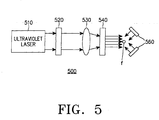
- FIG. 5 is a structure diagram illustrating a device for fabricating a polarization insensitive long period fiber grating in accordance with a fourth embodiment of the present invention.
- the device 500 for fabricating the polarization insensitive long period fiber grating includes a ultraviolet laser 510 for irradiating a ultraviolet laser beam, a ultraviolet polarizer 520 for converting a polarization status of the ultraviolet laser beam into a linear polarization status in parallel to a longitudinal direction of a fiber (f), a lens 530 for adjusting a focus of the ultraviolet laser beam from the ultraviolet polarizer 520, an amplitude mask 540 for selectively passing the ultraviolet laser beam from the lens 530, and at least one mirror 560 for reflecting the ultraviolet laser beam from the amplitude mask 540 to the outer circumferential surface of the fiber (f).
- the device 500 for fabricating the polarization insensitive long period fiber grating further includes a mount (not shown) for holding both ends of the fiber (f), so that the outer circumferential surface of the fiber (f) can be exposed to the ultraviolet laser beam from the amplitude mask 540.
- the device for fabricating the polarization insensitive long period fiber grating in accordance with the fourth embodiment of the present invention further includes the mirror 560 for irradiating the ultraviolet laser beam to both sides of the fiber (f).
- the mirror 560 reflects the ultraviolet laser beam having the linear polarization status from the amplitude mask 540 to be irradiated on the other side of the fiber (f), thus reducing the birefringence of the fiber due to asymmetric exposure to the ultraviolet laser beam.
- the device for fabricating the polarization insensitive long period fiber grating adjusts the polarization status of the ultraviolet laser beam irradiated on the fiber in the linear polarization status, and thus reduces the birefringence in the axial direction of the fiber. As a result, a property loss of the long period fiber grating is prevented.
- the device for fabricating the polarization insensitive long period fiber grating evenly irradiates the ultraviolet laser beam to both sides of the fiber, and thus decreases the birefringence of the fiber due to the geometrical asymmetry.
Landscapes
- Physics & Mathematics (AREA)
- General Physics & Mathematics (AREA)
- Optics & Photonics (AREA)
- Engineering & Computer Science (AREA)
- Manufacturing & Machinery (AREA)
- Optical Fibers, Optical Fiber Cores, And Optical Fiber Bundles (AREA)
- Lasers (AREA)
- Diffracting Gratings Or Hologram Optical Elements (AREA)
Applications Claiming Priority (2)
| Application Number | Priority Date | Filing Date | Title |
|---|---|---|---|
| KR2000045196 | 2000-08-04 | ||
| KR1020000045196A KR100342532B1 (ko) | 2000-08-04 | 2000-08-04 | 편광 무의존성 장주기 광섬유 격자 제조 장치 |
Publications (2)
| Publication Number | Publication Date |
|---|---|
| EP1178337A2 true EP1178337A2 (fr) | 2002-02-06 |
| EP1178337A3 EP1178337A3 (fr) | 2004-03-03 |
Family
ID=19681708
Family Applications (1)
| Application Number | Title | Priority Date | Filing Date |
|---|---|---|---|
| EP01117469A Withdrawn EP1178337A3 (fr) | 2000-08-04 | 2001-07-19 | Dispositif de fabrication d'un réseau dans une fibre à longue période insensible à la polarisation |
Country Status (4)
| Country | Link |
|---|---|
| US (1) | US6501881B2 (fr) |
| EP (1) | EP1178337A3 (fr) |
| JP (1) | JP2002098843A (fr) |
| KR (1) | KR100342532B1 (fr) |
Cited By (2)
| Publication number | Priority date | Publication date | Assignee | Title |
|---|---|---|---|---|
| CN102830464A (zh) * | 2012-09-05 | 2012-12-19 | 哈尔滨工程大学 | 一种基于单模-多模光纤光栅的双重滤波微结构分束器 |
| CN112698441A (zh) * | 2021-02-02 | 2021-04-23 | 深圳大学 | 一种可调控双折射的光纤光栅制备方法及制备装置 |
Families Citing this family (15)
| Publication number | Priority date | Publication date | Assignee | Title |
|---|---|---|---|---|
| US6614959B1 (en) * | 2000-07-27 | 2003-09-02 | Ciena Corporation | Methods of writing apodized fiber gratings and associated apparatuses |
| EP1345050A4 (fr) * | 2000-11-28 | 2005-10-12 | Fujikura Ltd | Procede et dispositif de fabrication d'un reseau de fibres optiques, reseau de fibres optiques, module optique et systeme de communication optique |
| US20030121289A1 (en) * | 2002-01-02 | 2003-07-03 | Benda John A. | Long period fiber Bragg gratings written with alternate side IR laser illumination |
| US7010195B2 (en) * | 2002-03-15 | 2006-03-07 | Fitel Usa Corp. | Fiber optic grating with tunable polarization dependent loss |
| US20040101240A1 (en) * | 2002-11-21 | 2004-05-27 | 3M Innovative Properties Company | Method to reduce birefringence and polarization mode dispersion in fiber gratings |
| JP2005055508A (ja) * | 2003-08-05 | 2005-03-03 | Fujikura Ltd | グレーティング型光部品製造方法、グレーティング型光部品製造装置、グレーティング型光部品製造方法又はグレーティング型光部品製造装置を用いて作製された光部品 |
| US20060159394A1 (en) * | 2005-01-19 | 2006-07-20 | Victor Grubsky | Method of and apparatus for manufacturing fiber grating devices |
| KR100813613B1 (ko) * | 2006-08-08 | 2008-03-17 | 광주과학기술원 | 광섬유 격자를 제조하는 방법과 장치, 및 이에 따른 광섬유격자가 형성된 광섬유 |
| CN103969741B (zh) * | 2014-05-11 | 2017-03-22 | 中国科学技术大学 | 一种正交错位光纤光栅的刻写装置和刻写方法 |
| CN104635295B (zh) * | 2015-03-17 | 2018-01-09 | 武汉烽理光电技术有限公司 | 一种在线光纤光栅制备系统 |
| KR102095216B1 (ko) * | 2018-05-29 | 2020-03-31 | 한국광기술원 | 대구경 광섬유 브래그 격자 형성장치 및 방법 |
| CN112059404B (zh) * | 2020-09-07 | 2021-07-27 | 中国科学院西安光学精密机械研究所 | 一种超细单晶光纤包层加工方法及系统 |
| WO2022165960A1 (fr) * | 2021-02-02 | 2022-08-11 | 深圳大学 | Procédé de fabrication de réseau de fibres et dispositif de fabrication capable de réguler la biréfringence |
| EP4305473A4 (fr) * | 2021-03-08 | 2024-08-28 | Teraxion Inc. | Réseau de bragg en volume dans un milieu en vrac cylindrique |
| CN114185129B (zh) * | 2022-02-15 | 2022-05-10 | 深圳奥斯诺导航科技有限公司 | 一种倾斜光栅偏振滤波器的刻写方法 |
Family Cites Families (12)
| Publication number | Priority date | Publication date | Assignee | Title |
|---|---|---|---|---|
| US5327515A (en) * | 1993-01-14 | 1994-07-05 | At&T Laboratories | Method for forming a Bragg grating in an optical medium |
| EP0635736A1 (fr) * | 1993-07-19 | 1995-01-25 | AT&T Corp. | Procédé pour former, dans des milieux optiques des perturbations d'indice de refraction avec biréfringence reduite |
| US5559907A (en) * | 1994-02-17 | 1996-09-24 | Lucent Technologies Inc. | Method of controlling polarization properties of a photo-induced device in an optical waveguide and method of investigating structure of an optical waveguide |
| US5604829A (en) * | 1995-04-17 | 1997-02-18 | Hughes Aircraft Company | Optical waveguide with diffraction grating and method of forming the same |
| GB2316760A (en) * | 1996-08-23 | 1998-03-04 | Univ Southampton | Fabricating optical waveguide gratings |
| US6414764B1 (en) * | 1996-12-02 | 2002-07-02 | Francois Ouellette | Ring interferometer configuration for writing gratings |
| WO1998029770A1 (fr) * | 1996-12-30 | 1998-07-09 | D-Star Technologies, Inc. | Formation par ultraviolet proche d'un reseau a indice de refraction au moyen d'un masque de phase |
| US5912999A (en) * | 1997-10-02 | 1999-06-15 | Minnesota Mining And Manufacturing Company | Method for fabrication of in-line optical waveguide index grating of any length |
| KR100265794B1 (ko) * | 1997-12-08 | 2000-09-15 | 윤종용 | 주기가 조절가능한 진폭 마스크 및 이를 이용한 장주기 격자 필터 제조장치 |
| JP3869121B2 (ja) * | 1998-06-26 | 2007-01-17 | 古河電気工業株式会社 | ファイバグレーティングの形成方法 |
| AU763596B2 (en) * | 1998-08-19 | 2003-07-24 | Samsung Electronics Co., Ltd. | Apparatus for manufacturing long-period fiber gratings and apparatus for manufacturing two-band long-period fiber gratings using the same |
| KR100315672B1 (ko) * | 1999-12-28 | 2001-11-29 | 윤종용 | 진폭 마스크를 이용한 절족화된 광섬유 격자의 제작 방법 |
-
2000
- 2000-08-04 KR KR1020000045196A patent/KR100342532B1/ko not_active Expired - Fee Related
-
2001
- 2001-07-19 EP EP01117469A patent/EP1178337A3/fr not_active Withdrawn
- 2001-07-27 JP JP2001228573A patent/JP2002098843A/ja active Pending
- 2001-07-30 US US09/917,975 patent/US6501881B2/en not_active Expired - Lifetime
Cited By (2)
| Publication number | Priority date | Publication date | Assignee | Title |
|---|---|---|---|---|
| CN102830464A (zh) * | 2012-09-05 | 2012-12-19 | 哈尔滨工程大学 | 一种基于单模-多模光纤光栅的双重滤波微结构分束器 |
| CN112698441A (zh) * | 2021-02-02 | 2021-04-23 | 深圳大学 | 一种可调控双折射的光纤光栅制备方法及制备装置 |
Also Published As
| Publication number | Publication date |
|---|---|
| JP2002098843A (ja) | 2002-04-05 |
| US20020031302A1 (en) | 2002-03-14 |
| US6501881B2 (en) | 2002-12-31 |
| KR100342532B1 (ko) | 2002-06-28 |
| EP1178337A3 (fr) | 2004-03-03 |
| KR20020011724A (ko) | 2002-02-09 |
Similar Documents
| Publication | Publication Date | Title |
|---|---|---|
| Grobnic et al. | Fiber Bragg gratings with suppressed cladding modes made in SMF-28 with a femtosecond IR laser and a phase mask | |
| US6009222A (en) | Optical fibre and optical fibre grating | |
| US5016967A (en) | Multi-core optical waveguide Bragg grating light redirecting arrangement | |
| EP0507889B1 (fr) | Filtre de discrimination de mode spatial transversal integre pour guide d'ondes optique | |
| US6501881B2 (en) | Device for fabricating polarization insensitive long period fiber grating | |
| US5883990A (en) | Low transmission loss optical fiber having a grating | |
| KR100282993B1 (ko) | 복잡한 스펙트럼 성형 응용을 위한 광신호 성형 장치 | |
| WO2000042459A1 (fr) | Reseau de diffraction pour fibre optique, procede de production correspondant et filtre pour fibre optique | |
| EP0850430A1 (fr) | Dispositifs de couplage optiques rendus selectifs pour la longueur d'onde, grace a un reseau | |
| US10605982B2 (en) | Multicore optical fiber with a core and a common cladding having a higher refractive index than the core, fiber Bragg grating, and method for manufacturing fiber Bragg grating | |
| US6233381B1 (en) | Photoinduced grating in oxynitride glass | |
| US6084996A (en) | Broadband long-period gratings | |
| GB2316761A (en) | Chirped optical fibre grating | |
| EP1333299A2 (fr) | Fibre optique et réseau de diffraction incliné dans une fibre optique | |
| CN112840255B (zh) | 倾斜光纤光栅 | |
| Haggans et al. | Narrow-depressed cladding fiber design for minimization of cladding mode losses in azimuthally asymmetric fiber Bragg gratings | |
| JPH1138238A (ja) | 長周期グレーティングを備えた光ファイバ及びその製造方法 | |
| US6766080B2 (en) | Optical waveguide type defraction grating device and a method of manufacturing thereof | |
| US6549706B2 (en) | Photoinduced grating in oxynitride glass | |
| Paschotta | Fiber bragg gratings | |
| US6915042B2 (en) | Slanted Bragg grating optical fiber and process for manufacturing such a fiber | |
| KR100377388B1 (ko) | 중첩된 장주기 광섬유 격자 제조 장치 | |
| JP3717307B2 (ja) | 光ファイバ型光部品 | |
| JP2001356221A (ja) | 光ファイバに書き込まれたグレーティングの偏波モード分散の補償 | |
| JPH095544A (ja) | 光ファイバグレーティング |
Legal Events
| Date | Code | Title | Description |
|---|---|---|---|
| PUAI | Public reference made under article 153(3) epc to a published international application that has entered the european phase |
Free format text: ORIGINAL CODE: 0009012 |
|
| 17P | Request for examination filed |
Effective date: 20010719 |
|
| AK | Designated contracting states |
Kind code of ref document: A2 Designated state(s): AT BE CH CY DE DK ES FI FR GB GR IE IT LI LU MC NL PT SE TR |
|
| AX | Request for extension of the european patent |
Free format text: AL;LT;LV;MK;RO;SI |
|
| PUAL | Search report despatched |
Free format text: ORIGINAL CODE: 0009013 |
|
| AK | Designated contracting states |
Kind code of ref document: A3 Designated state(s): AT BE CH CY DE DK ES FI FR GB GR IE IT LI LU MC NL PT SE TR |
|
| AX | Request for extension of the european patent |
Extension state: AL LT LV MK RO SI |
|
| RIC1 | Information provided on ipc code assigned before grant |
Ipc: 7G 02B 6/12 B Ipc: 7G 02B 6/34 B Ipc: 7G 02B 6/16 B Ipc: 7G 02B 6/293 A |
|
| 17Q | First examination report despatched |
Effective date: 20040521 |
|
| AKX | Designation fees paid |
Designated state(s): DE FR GB |
|
| STAA | Information on the status of an ep patent application or granted ep patent |
Free format text: STATUS: THE APPLICATION IS DEEMED TO BE WITHDRAWN |
|
| 18D | Application deemed to be withdrawn |
Effective date: 20051103 |