EP1178346A2 - Polarisierender Lichtstrahl-Kombinierer sowie Vorrichtungen mit polarisierenden Lichtstrahl-Kombinierern - Google Patents
Polarisierender Lichtstrahl-Kombinierer sowie Vorrichtungen mit polarisierenden Lichtstrahl-Kombinierern Download PDFInfo
- Publication number
- EP1178346A2 EP1178346A2 EP01114609A EP01114609A EP1178346A2 EP 1178346 A2 EP1178346 A2 EP 1178346A2 EP 01114609 A EP01114609 A EP 01114609A EP 01114609 A EP01114609 A EP 01114609A EP 1178346 A2 EP1178346 A2 EP 1178346A2
- Authority
- EP
- European Patent Office
- Prior art keywords
- prisms
- light
- light beam
- beam combiner
- prism
- Prior art date
- Legal status (The legal status is an assumption and is not a legal conclusion. Google has not performed a legal analysis and makes no representation as to the accuracy of the status listed.)
- Withdrawn
Links
Images




Classifications
-
- H—ELECTRICITY
- H04—ELECTRIC COMMUNICATION TECHNIQUE
- H04N—PICTORIAL COMMUNICATION, e.g. TELEVISION
- H04N1/00—Scanning, transmission or reproduction of documents or the like, e.g. facsimile transmission; Details thereof
- H04N1/46—Colour picture communication systems
- H04N1/48—Picture signal generators
- H04N1/486—Picture signal generators with separate detectors, each detector being used for one specific colour component
- H04N1/488—Picture signal generators with separate detectors, each detector being used for one specific colour component using beam-splitters
-
- G—PHYSICS
- G02—OPTICS
- G02B—OPTICAL ELEMENTS, SYSTEMS OR APPARATUS
- G02B27/00—Optical systems or apparatus not provided for by any of the groups G02B1/00 - G02B26/00, G02B30/00
- G02B27/28—Optical systems or apparatus not provided for by any of the groups G02B1/00 - G02B26/00, G02B30/00 for polarising
- G02B27/283—Optical systems or apparatus not provided for by any of the groups G02B1/00 - G02B26/00, G02B30/00 for polarising used for beam splitting or combining
Definitions
- the invention relates to a polarizing light beam combiner according to the Preamble of claim 1 and devices with polarizing light beam combiners according to claims 9 and 10.
- DE 41 32 025 C2 describes a device for deflecting a light beam, which a prism rotatably mounted with respect to an axis of rotation, a mirror surface and a reflective surface which is dependent on the angle of incidence of the light beam Has reflection and transmission properties, known.
- the prism consists of an inlet prism and an outlet prism together, these two prisms being essentially in relation to the axis of rotation add to a symmetrical mass distribution.
- the inlet prism has a light entry surface running transversely to the axis of rotation for the incident light beam and the outlet prism essentially one direction light exit surface for the deflected light beam on.
- the reflective surface is at the, transverse to the axis of rotation, opposite interfaces of inlet prism and outlet prism arranged.
- the arrangement of the reflection surface and mirror surface hit such that in the direction of the axis of rotation through the light entry surface passing light beam depending on the angle of incidence either from the Reflecting surface reflected on the mirror surface or by the reflecting surface is let through to the mirror surface.
- that of the mirror surface coming light beam either through the reflective surface to the light exit surface transmitted or from the reflection surface to the light exit surface reflected.
- a polarizing cube-shaped light beam combiner known from a pair of prisms cemented together on the diagonals. in this connection the prisms are precisely polished and bonded to minimize wavefront destruction to ensure. This combiner is especially for the Use with focused beams, experiments with pulsed lasers or for polarization cleaning for lasers in multimode operation with high power predestined.
- Such combiners are used, for example, in laser beam scanners, such as in US Pat US 5,233,188, DE-OS 196 21 138 or US 5,122,659 described used.
- semiconductor lasers are used via polarizing light beam combiners united into parallel rays, by means of which a surface is scanned.
- DE-OS 196 21 138 describes an optical scan or Scanning device in which the light of several laser diodes is transmitted through a beam composer is united.
- US 5,122,659 describes a radiation image reading device for stimulated phosphor foils, for increasing the Light intensity laser beams can be added using a beam combiner.
- the prisms are constructed and arranged in such a way that that the planes of the light entry and exit surfaces are not parallel Form surfaces. It is often also beneficial if these planes are not vertical stand on each other. As a result, back reflections occur only to a very small extent on.
- the laser beam and light entry surface are advantageously arranged such that that the laser beam no longer strikes the light entry surface perpendicularly, so that primary back reflections do not run back into the laser light source, so that again no disturbance of the stable laser emission occurs.
- the fluctuations in intensity of the light emitting surface of the second polygon prism emerging combined laser light reduced to almost zero because no or at least almost no disturbing interference effects on plane-parallel ones Surfaces occur.
- the interference effects are also called so-called Etalon effect and can be referred to as interference by simple words Reflections on edges are explained.
- Opposing surfaces through which light passes are advantageous or where light is reflected, not parallel to each other.
- the prisms triangular prisms the light exit surface of a triangular prism not parallel to the light entry surface of the other triangular prism is arranged.
- the triangular prisms along the respective hypotenuse surfaces are joined together, with opposing ones Leg surfaces of the triangular prisms are not of the same length. in principle it is sufficient if two opposing leg surfaces are of different lengths and are not arranged in parallel. This automatically ensures that the other two opposite leg surfaces are not parallel.
- the leg surfaces are of each triangular prism the same length. To ensure that opposite Leg surfaces do not run parallel to each other, must be in in this case the triangular prisms will be different. The length of the thigh surfaces of a triangular prism must not match the length of the leg surfaces of the other triangular prism.
- Any prisms can be used instead of triangular prisms.
- the Invention can equally well be advantageous for prisms with the base of a Quadrilaterals, pentagons or any polygons can be used.
- a multilayer dielectric film is arranged, whereby a on the Light-emitting surfaces of the two prisms, monochromatic, unpolarized light leaves the pair of prisms polarized at the light exit surface, the polarization rate is almost 100%.
- both will be Light entry surfaces of the prisms with coherent light, in particular laser light, irradiated.
- this is the light entry surface of the first prism illuminating light before hitting this light entry surface by a Half wave plate passes through.
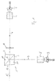
- Light beam combiner 1 schematically shows an embodiment of the polarizing according to the invention
- Light beam combiner 1 shown.
- the light beam combiner 1 is assigned by two light sources 2, 3 in the form of lasers each with Optics 4, 5 irradiated.
- the dash-dotted lines 6, 7 show the Beam path from the respective laser 2, 3 to the polarizing according to the invention
- the two laser light beams 6, 7 strike the respective light entry surfaces 8, 9 of the two triangular prisms 10, 11.
- the two triangular prisms 10, 11 are on their surface assigned to the respective hypotenuse, which are described below is called the hypotenuse surface, cemented together.
- a multilayer dielectric Film 13 arranged so that when irradiating the polarizing light beam combiner with, for example, monochromatic, unpolarized Light this film to a polarization that ultimately comes from the light beam combiner escaping light leads.
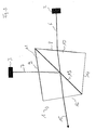
- Light beam combiner 1 shown in two-dimensional form.
- the polarizing light beam combiner 1 from two triangular prisms 10, 11, which at their respective Hypotenuse surfaces are connected to one another along a cementing line.
- the two triangular prisms 10, 11 have the legs shown in FIG. 2 surfaces assigned to the triangles, which in the following are called leg surfaces be designated.
- the second triangular prism 11 both leg surfaces through the light entry surface 9 and the light exit surface 12 formed.
- the leg surfaces of the first triangular prism 10 through the light entry surface 8 and one not previously designated Leg surface 14 formed.
- the angle ⁇ of the respective triangular prism is 10, 11 between the mutually associated leg surface pairs 8, 14 or 9. 10 not equal to 90 °.
- This choice of angle of ⁇ compared to the known polarizing light beam combiner cubes have the advantage that on the one hand intensity fluctuations minimized after interference due to interference effects and annoying back reflections of the polarization optics with regard to a stable Laser emission can be eliminated.
- FIG 3 is a schematic representation of an inventive, polarizing Light beam combiner 1 'shown according to a second embodiment.
- This light beam combiner 1 ' differs from the light beam combiner 1 according to the first embodiment only in that the Triangular prisms 10, 11 are made up of right triangles. by virtue of the different leg lengths of opposite leg surfaces the light entry and exit surfaces are nevertheless not parallel.
- Another embodiment, not shown, would be one of two isosceles Triangular combiner. Every triangular prism would have to do this 10, 11 have two leg surfaces 9, 12, 8.1, of equal length, the respective length of the leg surfaces of the triangular prisms is different.
- Another possible embodiment is a completely irregular Triangles of existing combiners.
- the light beam combiner 1 shows a further polarizing light beam combiner according to the invention 1 "according to a fifth exemplary embodiment.
- the light beam combiner 1 are the prisms 10, 11 in turn joined together along side 13, however, is the base of the prism 11 formed as a triangle and the base of the prism 10 as a square.
- the light beam combiner fulfills 1 "according to the fifth exemplary embodiment the same requirements as the two light beam combiners 1 and 1 'according to the first two embodiments, i. H. that the planes of at least one light entry surface 8, 9 and opposite Light exit surface 12 Include angles not equal to 0 ° with each other.
- FIG. 5 shows a further exemplary embodiment of a polarizing device according to the invention Beam combination 1 '' 'shown.
- This light beam combiner 1 '' ' consists of a triangular prism 10 and a square prism 11.
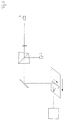
- FIG. 6 now shows a device for reading out a stimulable phosphor sheet 17 shown.
- a laser light merging according to 1 described above of course each of the above Light beam combiner according to the invention can be used.
- a stimulating Phosphor film 17 is that of the two light sources 2, 3 in the form of laser light combined light beam 15 through a movable mirror 18, such as one Vibration mirror or a polygon, deflected onto the phosphor film 17.
- a movable mirror 18, such as one Vibration mirror or a polygon deflected onto the phosphor film 17.
- the combined light beam or laser beam 15 along the scanning direction B deflected and caused a stimulation of the phosphor sheet 17.
- a transport device guides the phosphor film in the direction of arrow A, so that by the interaction of the scanning direction B and the transport direction A read out the complete stimulable Phosphor film 17 is possible.
- Slow scan transport device crystallized out.
- the radiation generated during the stimulation is transmitted through an optical fiber 19 passed to a photomultiplier 20 and that generated on the photomultiplier 20 Output signal fed to a computer 21 for evaluation.
- the inventive light beam combiner explained in detail above also in a device for exposing photosensitive material be used.
- a device for exposing photosensitive material is shown schematically in FIG. 7.
- This device has, for example, three color lasers 30 to 32 the colors red, green and blue.
- the light of the bottom is in Fig.
- Color laser 30 - such as red light - deflected by a mirror 33 by means of a Light beam combiner 34 according to the invention with the green light of the color laser 31 combined and the resulting red and green laser light beam in turn by means of a light beam combiner 35 according to the invention with the Blue light of the color laser 32 combined and the light beam now resulting 36 via a movable mirror 37, for example an oscillating mirror or a polygon, through a lens 38 onto a photosensitive material 39 directed.
- An F-theta lens has been found to be particularly suitable as the lens 38 exposed.
- the two light beam combiners can according to the embodiments 2 to 5 may be formed. Of course there is also a combination of two, four or more light beams possible.
Landscapes
- Physics & Mathematics (AREA)
- Engineering & Computer Science (AREA)
- Multimedia (AREA)
- Signal Processing (AREA)
- General Physics & Mathematics (AREA)
- Optics & Photonics (AREA)
- Optical Elements Other Than Lenses (AREA)
- Polarising Elements (AREA)
Abstract
Description
- Fig. 1
- eine schematische Darstellung einer Laserlichtzusammenführung mit einem ersten Ausführungsbeispiel eines erfindungsgemäßen polarisierenden Lichtstrahl-Kombinierers,
- Fig. 2
- eine schematische Darstellung des erfindungsgemäßen polarisierenden Lichtstrahl-Kombinierers gemäß dem ersten Ausführungsbeispiel,
- Fig. 3
- eine schematische Darstellung des erfindungsgemäßen polarisierenden Lichtstrahl-Kombinierers gemäß einem zweiten Ausführungsbeispiel;
- Fig. 4
- eine schematische Darstellung des erfindungsgemäßen polarisierenden Lichtstrahl-Kombinierers gemäß einem dritten Ausführungsbeispiel;
- Fig. 5
- eine schematische Darstellung des erfindungsgemäßen polarisierenden Lichtstrahl-Kombinierers gemäß einem vierten Ausführungsbeispiel:
- Fig. 6
- eine schematische Darstellung einer Vorrichtung zum Auslesen einer stimulierbaren Phosphorfolie mit einem erfindungsgemäßen polarisierbaren Lichtstrahl-Kombinierer; und
- Fig. 7
- eine schematische Darstellung einer Vorrichtung zum Belichten von lichtempfindlichem Material mit zwei erfindungsgemäßen, polarisierenden Lichtstrahl-Kombinierern.
Claims (17)
- Polarisierender Lichtstrahl-Kombinierer (1) zum Addieren von Laserstrahlen mit wenigstens zwei aneinandergefügten Prismen (10, 11), wobei ein Prisma (10) eine Lichteintrittsfläche (8) und ein Prisma (11) sowohl eine Lichteintrittsfläche (9) als auch eine Lichtaustrittsfläche (12) aufweist, dadurch gekennzeichnet, daß die Prismen derart aufgebaut und angeordnet sind, daß die Ebenen von wenigstens einer Lichteintrittsfläche (8, 9) und gegenüberliegender Lichtaustrittsfläche (12) Winkel ungleich 0° miteinander einschließen.
- Polarisierender Lichtstrahl-Kombinierer (1) nach Anspruch 1, dadurch gekennzeichnet, daß die Prismen (10, 11) zwei entlang der jeweiligen Hypotenusenflächen (13) aneinandergefügte Dreiecksprismen sind, wobei gegenüberliegende Schenkelflächen (9, 14) und/oder (8, 12) der Dreiecksprismen ungleich lang sind.
- Polarisierender Lichtstrahl-Kombinierer (1) nach Anspruch 2, dadurch gekennzeichnet, daß die Dreiecksprismen (10, 11) identisch aufgebaut und spiegelsymmetrisch zur Hypotenusenfläche (13) angeordnet sind.
- Polarisierender Lichtstrahl-Kombinierer (1) nach Anspruch 1, dadurch gekennzeichnet, daß jedes der Dreiecksprismen (10, 11) zwei gleich lange Schenkelflächen (9, 12; 8, 14) aufweist, wobei die jeweilige Länge der Schenkelflächen der Dreiecksprismen unterschiedlich ist.
- Polarisierender Lichtstrahl-Kombinierer (1) nach Anspruch 1, dadurch gekennzeichnet, daß die Prismen (10, 11) entlang einer Seite (13) aneinandergefügte Prismen sind, wobei die Grundfläche wenigstens eines Prismas ein Vieleck ist.
- Polarisierender Lichtstrahl-Kombinierer (1) nach einem der vorhergehenden Ansprüche 1 bis 5, dadurch gekennzeichnet, daß die Prismen (10, 11) verkittet sind.
- Polarisierender Lichtstrahl-Kombinierer (1) nach einem der Ansprüche 1 bis 5, dadurch gekennzeichnet, daß zwischen den Prismen (10, 11) ein mehrschichtiger dielektrischer Film angebracht ist.
- Polarisierender Lichtstrahl-Kombinierer (1) nach einem der Ansprüche 1 bis 5, dadurch gekennzeichnet, daß sich zwischen den Prismen ein Luftspalt befindet.
- Vorrichtung zum Auslesen einer stimulierbaren Phosphorfolie (17) mit mehreren Laserlichtquellen (2, 3), einem polarisierenden Lichtstrahl-Kombinierer (1) zum Addieren der Laserstrahlen, einem beweglichen Spiegel (18) zum Führen des Laserstrahls über die und zum Anregen der Phosphorfolie, einer Lichtleiter-Anordnung (19) zum Sammeln der von der angeregten Phosphorfolie emittierten Strahlung, einem Photomultiplier und einer Bildverarbeitungseinheit, dadurch gekennzeichnet, daß der polarisierende Lichtstrahl-Kombinierer (1) zwei aneinandergefügte Prismen (10, 11) aufweist, wobei ein Prisma (10) eine Lichteintrittsfläche (8) und ein Prisma (11) sowohl eine Lichteintrittsfläche (9) als auch eine Lichtaustrittsfläche (12) aufweist und daß die Prismen derart aufgebaut und angeordnet sind, daß wenigstens eine Lichteintrittsfläche (8, 9) und die gegenüberliegende Lichtaustrittsfläche (12) nicht parallel sind.
- Vorrichtung zum Belichten von lichtempfindlichem Material (39) mit mehreren Laserlichtquellen (2, 3), wobei das Licht der Laserlichtquellen mittels polarisierender Lichtstrahl-Kombinierer (1) zusammenführbar ist, und mit einem beweglichen Spiegel (37) und einer Abbildungsoptik zum Führen des zusammengeführten Laserstrahls über das lichtempfindliche Material (39), dadurch gekennzeichnet, daß die polarisierenden Lichtstrahl-Kombinierer (1) zwei aneinandergefügte Prismen (10, 11) aufweisen, wobei ein Prisma (10) eine Lichteintrittsfläche (8) und ein Prisma (11) sowohl eine Lichteintrittsfläche (9) als auch eine Lichtaustrittsfläche (12) aufweist und daß die Prismen derart aufgebaut und angeordnet sind, daß wenigstens eine Lichteintrittsfläche (8, 9) und die gegenüberliegende Lichtaustrittsfläche (12) nicht parallel sind.
- Vorrichtung nach Anspruch 9 oder 10, dadurch gekennzeichnet, daß die Prismen (10, 11) zwei entlang der jeweiligen Hypotenusenflächen (13) aneinandergefügte Dreiecksprismen sind, wobei gegenüberliegende Schenkelflächen (9, 14) und/oder (8, 12) der Dreiecksprismen ungleich lang sind.
- Vorrichtung nach Anspruch 11, dadurch gekennzeichnet, daß die Dreiecksprismen (10, 11) identisch aufgebaut und spiegelsymmetrisch zur Hypotenusenfläche (13) angeordnet sind.
- Vorrichtung nach Anspruch 9 oder 10, dadurch gekennzeichnet, daß jedes der Dreiecksprismen (10, 11) zwei gleich lange Schenkelflächen (9, 12; 8, 14) aufweist, wobei die jeweilige Länge der Schenkelflächen der Dreiecksprismen unterschiedlich ist.
- Vorrichtung nach Anspruch 9 oder 10, dadurch gekennzeichnet, daß die Prismen (10, 11) entlang einer Seite (13) aneinandergefügte Prismen sind, wobei die Grundfläche wenigstens eines Prismas ein Vieleck ist.
- Vorrichtung nach Anspruch 9 oder 10, dadurch gekennzeichnet, daß die Prismen (10, 11) verkittet sind.
- Vorrichtung nach Anspruch 9 oder 10, dadurch gekennzeichnet, daß zwischen den Prismen (10, 11) ein mehrschichtiger dielektrischer Film angebracht ist.
- Vorrichtung nach Anspruch 9 oder 10, dadurch gekennzeichnet, daß sich zwischen den Prismen ein Luftspalt befindet.
Applications Claiming Priority (2)
| Application Number | Priority Date | Filing Date | Title |
|---|---|---|---|
| DE10037947 | 2000-08-03 | ||
| DE2000137947 DE10037947A1 (de) | 2000-08-03 | 2000-08-03 | Polarisierender Lichtstrahl-Kombinierer sowie Vorrichtungen mit polarisierenden Lichtstrahl-Kombinierern |
Publications (2)
| Publication Number | Publication Date |
|---|---|
| EP1178346A2 true EP1178346A2 (de) | 2002-02-06 |
| EP1178346A3 EP1178346A3 (de) | 2004-03-24 |
Family
ID=7651248
Family Applications (1)
| Application Number | Title | Priority Date | Filing Date |
|---|---|---|---|
| EP01114609A Withdrawn EP1178346A3 (de) | 2000-08-03 | 2001-06-19 | Polarisierender Lichtstrahl-Kombinierer sowie Vorrichtungen mit polarisierenden Lichtstrahl-Kombinierern |
Country Status (2)
| Country | Link |
|---|---|
| EP (1) | EP1178346A3 (de) |
| DE (1) | DE10037947A1 (de) |
Cited By (2)
| Publication number | Priority date | Publication date | Assignee | Title |
|---|---|---|---|---|
| CN102195231A (zh) * | 2011-03-28 | 2011-09-21 | 中国科学院西安光学精密机械研究所 | 用于高功率半导体激光器的功率扩展器 |
| EP3236308A1 (de) * | 2016-04-19 | 2017-10-25 | LIMO Patentverwaltung GmbH & Co. KG | Laservorrichtung |
Family Cites Families (7)
| Publication number | Priority date | Publication date | Assignee | Title |
|---|---|---|---|---|
| GB1141599A (en) * | 1965-07-02 | 1969-01-29 | Ibm | Polarized light separator |
| US5235444A (en) * | 1988-08-26 | 1993-08-10 | U.S. Philips Corporation | Image projection arrangement |
| US5194980A (en) * | 1992-05-29 | 1993-03-16 | Eastman Kodak Company | Thresholded, high power laser beam scanning system |
| US5539578A (en) * | 1993-03-02 | 1996-07-23 | Olympus Optical Co., Ltd. | Image display apparatus |
| US5716122A (en) * | 1994-08-25 | 1998-02-10 | Nikon Corporation | Optical apparatus using polarizing beam splitter |
| US5982541A (en) * | 1996-08-12 | 1999-11-09 | Nationsl Research Council Of Canada | High efficiency projection displays having thin film polarizing beam-splitters |
| US6052231A (en) * | 1998-01-21 | 2000-04-18 | International Business Machines Corporation | Beam dividing elements permitting projection of an image with high contrast |
-
2000
- 2000-08-03 DE DE2000137947 patent/DE10037947A1/de not_active Ceased
-
2001
- 2001-06-19 EP EP01114609A patent/EP1178346A3/de not_active Withdrawn
Cited By (6)
| Publication number | Priority date | Publication date | Assignee | Title |
|---|---|---|---|---|
| CN102195231A (zh) * | 2011-03-28 | 2011-09-21 | 中国科学院西安光学精密机械研究所 | 用于高功率半导体激光器的功率扩展器 |
| CN102195231B (zh) * | 2011-03-28 | 2014-03-12 | 中国科学院西安光学精密机械研究所 | 用于高功率半导体激光器的功率扩展器 |
| EP3236308A1 (de) * | 2016-04-19 | 2017-10-25 | LIMO Patentverwaltung GmbH & Co. KG | Laservorrichtung |
| JP2017194686A (ja) * | 2016-04-19 | 2017-10-26 | リモ パテントフェルヴァルトゥング ゲーエムベーハー ウント コー.カーゲーLIMO Patentverwaltung GmbH & Co.KG | レーザ装置 |
| RU2654993C1 (ru) * | 2016-04-19 | 2018-05-23 | Лимо Патентфервальтунг Гмбх Унд Ко. Кг | Лазерное устройство |
| US10254552B2 (en) | 2016-04-19 | 2019-04-09 | LIMO GmbH | Laser array |
Also Published As
| Publication number | Publication date |
|---|---|
| DE10037947A1 (de) | 2002-02-21 |
| EP1178346A3 (de) | 2004-03-24 |
Similar Documents
| Publication | Publication Date | Title |
|---|---|---|
| DE502007012156C5 (de) | Vorrichtung zur strahlformung | |
| DE69132049T3 (de) | Hochleistungs-lichtquelle | |
| DE69119317T2 (de) | Lasergenerator | |
| DE69611245T2 (de) | Diodengepumpter, fasergekoppelter laser mit depolarisiertem pumpstrahl | |
| DE69731148T2 (de) | Festkörperlaserverstärker | |
| DE69115169T2 (de) | Vorrichtung zum Mischen von Licht aus Halbleiterlasern. | |
| DE112005001847B4 (de) | Verfahren und Vorrichtung zur Bildung eines kristallisierten Films | |
| DE102017205889B4 (de) | Optische Anordnung und Verfahren zur Laserinterferenzstrukturierung einer Probe | |
| DE4124311A1 (de) | Anordnung zur kohaerenzreduktion und strahlformung eines laserstrahls | |
| DE2802417A1 (de) | Abtastvorrichtung | |
| DE2413423C2 (de) | Verfahren zum Einschreiben in bzw. Auslesen aus einem beweglichen optischen Informationsträger und Vorrichtung zur Durchführung des Verfahrens | |
| DE3726375A1 (de) | Laserdruckeinrichtung mit einer vorrichtung zur kombination mehrerer lichtstrahlen | |
| DE112015003430T5 (de) | Halbleiter-Laservorrichtung | |
| EP3236308B1 (de) | Laservorrichtung | |
| DE102016211339A1 (de) | Laserlinienprojektor zur Reduktion von Granulation | |
| DE68916136T2 (de) | Laservorrichtungen und Lasersystem mit diesen Vorrichtungen. | |
| DE69018759T2 (de) | Optisches Abtastgerät. | |
| DE2814476A1 (de) | Interferometer mit einer spule aus einem einmode-wellenleiter | |
| DE102006050155B4 (de) | Anordnungen zur Formung von Laserstrahlen | |
| DE10215162A1 (de) | Strahlteilervorrichtung bzw. Laserrastermikroskop | |
| DE2505774B2 (de) | Justiervorrichtung für eine Laseranordnung aus einem Leistungslaser und einem Justierlaser | |
| EP1178346A2 (de) | Polarisierender Lichtstrahl-Kombinierer sowie Vorrichtungen mit polarisierenden Lichtstrahl-Kombinierern | |
| DE102020205849B4 (de) | Anordnung optischer Elemente für die Ausbildung von Strukturmustern | |
| DE102004045914B4 (de) | Verfahren und Vorrichtung zur Überlagerung von Strahlenbündeln | |
| EP0457024A2 (de) | Laserleistungsmessung |
Legal Events
| Date | Code | Title | Description |
|---|---|---|---|
| PUAI | Public reference made under article 153(3) epc to a published international application that has entered the european phase |
Free format text: ORIGINAL CODE: 0009012 |
|
| AK | Designated contracting states |
Kind code of ref document: A2 Designated state(s): AT BE CH CY DE DK ES FI FR GB GR IE IT LI LU MC NL PT SE TR |
|
| AX | Request for extension of the european patent |
Free format text: AL;LT;LV;MK;RO;SI |
|
| PUAL | Search report despatched |
Free format text: ORIGINAL CODE: 0009013 |
|
| AK | Designated contracting states |
Kind code of ref document: A3 Designated state(s): AT BE CH CY DE DK ES FI FR GB GR IE IT LI LU MC NL PT SE TR |
|
| AX | Request for extension of the european patent |
Extension state: AL LT LV MK RO SI |
|
| RIC1 | Information provided on ipc code assigned before grant |
Ipc: 7H 04N 1/48 B Ipc: 7H 04N 1/04 B Ipc: 7G 02B 27/28 A |
|
| 17P | Request for examination filed |
Effective date: 20040924 |
|
| AKX | Designation fees paid |
Designated state(s): AT BE CH CY DE DK ES FI FR GB GR IE IT LI LU MC NL PT SE TR |
|
| RAP1 | Party data changed (applicant data changed or rights of an application transferred) |
Owner name: AGFA-GEVAERT HEALTHCARE GMBH |
|
| STAA | Information on the status of an ep patent application or granted ep patent |
Free format text: STATUS: THE APPLICATION IS DEEMED TO BE WITHDRAWN |
|
| 18D | Application deemed to be withdrawn |
Effective date: 20060419 |