EP1178426A2 - Medizinisches Datenverwaltungssystem - Google Patents
Medizinisches Datenverwaltungssystem Download PDFInfo
- Publication number
- EP1178426A2 EP1178426A2 EP01118637A EP01118637A EP1178426A2 EP 1178426 A2 EP1178426 A2 EP 1178426A2 EP 01118637 A EP01118637 A EP 01118637A EP 01118637 A EP01118637 A EP 01118637A EP 1178426 A2 EP1178426 A2 EP 1178426A2
- Authority
- EP
- European Patent Office
- Prior art keywords
- patient
- display
- data
- image
- managing system
- Prior art date
- Legal status (The legal status is an assumption and is not a legal conclusion. Google has not performed a legal analysis and makes no representation as to the accuracy of the status listed.)
- Withdrawn
Links
- 238000007689 inspection Methods 0.000 claims abstract description 13
- 230000006870 function Effects 0.000 description 4
- 230000015654 memory Effects 0.000 description 3
- 238000003384 imaging method Methods 0.000 description 2
- 238000000034 method Methods 0.000 description 2
- 230000003287 optical effect Effects 0.000 description 2
- 238000013518 transcription Methods 0.000 description 1
- 230000035897 transcription Effects 0.000 description 1
Images




Classifications
-
- G—PHYSICS
- G16—INFORMATION AND COMMUNICATION TECHNOLOGY [ICT] SPECIALLY ADAPTED FOR SPECIFIC APPLICATION FIELDS
- G16H—HEALTHCARE INFORMATICS, i.e. INFORMATION AND COMMUNICATION TECHNOLOGY [ICT] SPECIALLY ADAPTED FOR THE HANDLING OR PROCESSING OF MEDICAL OR HEALTHCARE DATA
- G16H10/00—ICT specially adapted for the handling or processing of patient-related medical or healthcare data
- G16H10/60—ICT specially adapted for the handling or processing of patient-related medical or healthcare data for patient-specific data, e.g. for electronic patient records
-
- G—PHYSICS
- G16—INFORMATION AND COMMUNICATION TECHNOLOGY [ICT] SPECIALLY ADAPTED FOR SPECIFIC APPLICATION FIELDS
- G16H—HEALTHCARE INFORMATICS, i.e. INFORMATION AND COMMUNICATION TECHNOLOGY [ICT] SPECIALLY ADAPTED FOR THE HANDLING OR PROCESSING OF MEDICAL OR HEALTHCARE DATA
- G16H40/00—ICT specially adapted for the management or administration of healthcare resources or facilities; ICT specially adapted for the management or operation of medical equipment or devices
- G16H40/60—ICT specially adapted for the management or administration of healthcare resources or facilities; ICT specially adapted for the management or operation of medical equipment or devices for the operation of medical equipment or devices
- G16H40/63—ICT specially adapted for the management or administration of healthcare resources or facilities; ICT specially adapted for the management or operation of medical equipment or devices for the operation of medical equipment or devices for local operation
Definitions
- the present invention relates to a medical data managing system for managing data on a patient.
- a patient received in a hospital waits his (her) turn to be examined in a waiting room.
- the patient is called by name and is informed that his (her) turn comes, he (she) enters a consulting room to be examined.
- a large number of patients wait for an examination, a long time is taken for waiting.
- a personal computer is used to sequentially display, on a display, the time that each patient is received.
- the hospital a doctor and a receptionist
- the hospital can grasp the waiting situation of the patients.
- the hospital can grasp the waiting situation of patients but the patients cannot know it.
- the invention is characterized by having the following arrangement.
- Fig. 1 shows a structure of a medical data managing system for collectively managing and processing patient data, such as image data, inspection (measured) data, medical examination data on others obtained by a medical apparatus.
- An ophthalmologic apparatus is usedas the medical apparatus in the present embodiment.
- Personal computers 1a and 1b for managing patient data are put in a consulting room 120a and a reception room 120b.
- a medical data managing software 10 is recorded (installed) in nonvolatile memories (not shown) of the personal computers 1a and 1b.
- the personal computer 1b provided in the reception room 120b is used as a server for recording the patient data
- the personal computer 1a provided in the consulting room 120a is used as a terminal.
- the personal computer 1a and the personal computer 1b are connected to each other through a LAN cable and various data stored on the server side (personal computer 1b) can be managed on the terminal side (personal computer 1a).
- the medical apparatus (a fundus camera 20 and a slit lamp 30 in the embodiment) is connected to the personal computer 1a.
- An imaging system such as a CCD camera, a digital camera (not shown) or the like for capturing (obtaining) images is preliminarily provided to each of the fundus camera 20 and the slit lamp 30, so that image data obtained by each imaging system is inputted into the personal computer 1a, and the personal computer 1b via the input section 5.
- Reference numerals 2a and 2b designate displays for which a general purposed display, such as a LCD or CRT monitor, can be used.
- the displays 2a and 2b are connected to the personal computers 1a and 1b, respectively.
- a display 2c for displaying waiting situation information of the patients is put in the waiting room for waiting the medical examination, and is connected to the personal computer 1b.
- Reference numeral 3 denotes a CCD camera which is connected to the personal computer 1b and provided in a corner of the waiting room 120c to capture the whole waiting room.
- the image of the waiting room 120c is displayed on displays 2a and 2b by using the software 10. This will be described below in detail.
- Reference numeral 4 denotes a card reader for reading a hospital identification card (not shown) which records personal data such as code (number) for recognizing a patient. By passing the hospital identification card through the card reader 4, a patient is received. While the card reader is used in the embodiment, it is not restricted but a device capable of carrying out a work for receiving the patient may be used. For example, in the case that personal data are bar code, a device for reading the bar code may be used. Moreover, the receiving work may be carried out through manual input by using a keyboard even if such a device is not used.
- an operation screen for managing the patient data is displayed on the display 2a (2b).
- the operation screen is mainly made up of four processing screens.
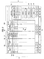
- the operation screens are respectively shown in Figs. 2 to 5, and each of them will be explained.
- a patient list screen is first displayed on the display 2a (2b) (see Fig. 2).
- This screen serves as a main screen with which indication of a list of already registered patients, search for a patient, and receipt (registration) of a new patient, and the like can be executed.
- the list of registered patients is indicated in order as a patient 50a, a patient 50b .... in a display column 50.
- a respective patient folder is prepare and the patient data is recorded in nonvolatile memories (not shown) of the personal computer 1b.
- a folder 12a for the patient 50a and a folder 12b for the patient 50b have been prepared, respectively.
- a vertical row (a column) is provided, which includes a button (icon) group 51 for searching a registered patient, a registration button (icon) 52 for new registration, an open (disclosure) button (icon) 53 for retrieving details of individual patient data, and a display button (icon) 55 for displaying the image from the camera 3 on the screen.
- a cursor mark 110 shown on the display 2a (2b) is moved onto a desired button (icon) with using the mouse (not shown), and then a button on the mouse is clicked.
- a button group 51 includes a display condition selection button (icon) 51a for changing display conditions in a display column 50. By using (clicking) a pull-down button (icon) on the right endof the button 51a, the display conditions can be selected.
- a display condition selection button (icon) 51a for changing display conditions in a display column 50.
- the display conditions can be selected from “all patients” for displaying all registered patients, “received” for displaying only received patients (unexamined patients), “all coming patients” for displaying coming patients, “inspected” for displaying only tested (inspected) patients and “examined” for displaying only examined patients.
- the reference numeral 51b denotes a status button for specifying the status of a patient (received, inspected, examined and finished).
- An item column for patient data displayed on the display column 50 includes a code column 56a indicating a registration number (code number) of a patient, a name column 56b indicating a name of a patient, a status column 56c indicating the status of a patient (received, inspected, examined, finished), and an elapsed time column 56d indicating a time elapsed after a patient is received.
- the elapsed time column 56d displays the time elapsed after the reception time in the embodiment, it is preferable that such information as to indicate the waiting time of a patient, for example, a reception time should be displayed.
- shortcut button (icon) group 100 is provided so that 12 pieces of shortcut buttons (icons) 100-a to 100-l can be used.
- the shortcut buttons (icons) provided in this embodiment include a button (icon) 100a for movement to the main screen, a button (icon) 100b for displaying the patient list, abutton (icon) 100c for inputting image data from the fundus camera 20, a button (icon) 100d for inputting image data from the slit lamp 30, abutton (icon) 100e for displaying, in a thumbnail fashion, all image data stored in the Queue folder (not shown), and a button (icons) 100f for outputting selected image data using the printer (not shown) .
- no task is assigned to the remaining buttons (icons) 100-g to 100-l.
- a menu bar 54 is displayed, which contains items of "File”, “Patient”, “Measure”, “Set”, and “Help”, and main functions (such as switch of a displayed screen) may be selected and used via this menu bar 54.
- Fig. 3 shows a screen with which a new patient is registered, or registered patient data is displayed.
- This registration screen can be displayed upon operation of the button 52 or the button 53 shown in Fig. 2.
- buttons (icons) are displayed in a hierarchical structure view (tree view 84), which respectively identify collected medical data such as image data obtained till now and measured data, and their stored contents or conditions are visually grasped.
- a patient data registration screen 60 is used to register a new patient.
- Input items of the patient data are "Name”, “Phonetic transcription”, “Sex”, “Birthday”, “Code”, “Day of first medical examination”, “Address”, “Tel. No.” and the like.
- Reference numeral 61 designates an OK button (icon) for executing registration
- 62 is a cancel button (icon) for canceling registration.
- Fig. 4 shows an image input (capture) screen with which patient's eye image data obtained by the fundus camera 20 or the slit lamp 30 is input (captured) into the PC 1b (1a).
- Reference numeral 70 designates a main image box, in which a latest inputted image is shown largely.
- 71 is a thumbnail indication box, in which the inputted images are displayed sequentially as thumbnail images 70a, 70b.
- Reference numeral 73 designates a set button (icon) group for setting data of eye examination, such as date of eye examination, designation of right or left eye, an image format and image capture mode, with respect to the inputted image.
- the image of patient's eye is inputted from the ophthalmologic apparatus (the fundus camera 20 or the slit lamp 30) by clicking an input button (icon) 74.
- the input operation for the image data may be carried out using a joystick or a foot switch (both not shown) provided in the ophthalmologic apparatus other than the use of the input button 74.
- Reference numeral 75 is a finish button (icon) for finishing the image input operation, and returning to the latest previous operation screen.
- Fig. 5 shows an image storage screen in which the image data stored in the folder is displayed.
- a hierarchical structure view (tree view 84) in date order or in item order (a fundus image, a slit image, etc.).
- a radio button 85 may be used to alter the hierarchical structure.
- a button (icon) for example, a fundus image button (icon) 84a
- the image data corresponding to the selected button (icon) is displayed as thumbnails 88a, 88b in the screen 80.
- buttons (icons) set in a date selection tool bar 81 for selecting a date of an image to be displayed, a kind selection tool bar 82 for selecting a kind of an image to be displayed, and a control tool bar 83 for designating a displaying condition such as a left or right eye, maybe selectively used to select a thumbnail image to be displayed on the display screen 80.
- Reference numeral 86 is an output button (icon) for outputting the thumbnail image displayed on the display screen 80 (for usage other than the image data to be used in the software 10). Beside the output button 86, a button (icon) 86a for a pulling down menu is provided, and by clicking the button 86a, the output type (form) may be set variously.
- the software 10 in the personal computers 1a and 1b is started up and the "all coming patients" is selected through the button 51a, so that a main screen (patient list screen) is displayed (see Fig. 2).
- a hospital identification card brought by a patient is passed through the card reader 4 in the reception room 120b so that the reception of the patient in the software 10 is completed.
- each data on the code, name and state (status) of the patient are displayed on each item column of the display column 50.
- a status column 56c for the patient passing the hospital identification card through the card reader 4.
- an elapsed time (hour, minute, second) based on a time (reception) that the hospital identification card is passed through the card reader 4 is displayed on an elapsed time column 56d.
- the elapsed time is measured by utilizing a clock function in the personal computer 1a (1b) and is updated at any time.
- a display 2c put in the waiting room 120c always displays only the name of a patient, the state of the patient (received, inspected, examined) and the elapsed time based on a program of the software 10 (see Fig. 7). Consequently, the patient waiting in the waiting room can see the display 2c to easily confirm the numbers of inspected and examined patients and the number of patients waiting for an examination before a certain patient.
- a reference number for the order of passage can be given to the patient after passing the hospital identification card and displayed on the display 2c in place of the name of the patient in order to protect privacy, for example.
- the patient called for an inspection enters the consulting room 120a and is inspected by using a fundus camera 20 and a slit lamp 30.
- a work is carried out on the image input screen (see Fig. 4) and the image storage screen (see Fig. 5) to input image data on the patient to the personal computer 1b.
- a doctor or a receptionist selects the inspected patient through the screen 50 and sets the state of the patient to the "inspected" by using the button 51b.
- An examination is carried out for the inspected patient based on the image data inputted during the inspection. Similarly, the state of the examined patient is set to "examined” by using the button 51b. The elapsed time for the patient thus inspected and examined through the button 51b is displayed as 0 in the display column.
- the software 10 in the embodiment is programmed such that the patient data displayed in the display column 50 is updated every one minute. If the state of the patient is changed on the personal computer 1a side, the state of the patient in the display column 50 which is displayed on the personal computer 1b side is also changed during the update of the display column 50. Accordingly, if the state of the patient is changed through one of the personal computers, the contents of the change are reflected in the state of the patient displayed on all the displays (2a, 2b, 2c) during the update.
- the "finished” is selected through the button 51b.
- the patient for which the “finished” is selected is not displayed on the display 50 until the "all patients” is selected through the button 51a.
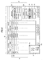
- an image window 57 appears in a top screen (first screen) on the display 2b when the button 55 on the main screen (see Fig. 2) is clicked in the personal computer 1b (see Fig. 6).
- the image of the waiting room 120c captured by the camera 3 is displayed on the window 57 in real time.
- the same operation is carried out so that the window 57 can be displayed, and the image of the waiting room 120c can be displayed in real time through the personal computer 1b.
- the software 10 is programmed so that the window 57 is always displayed on the top screen. Consequently, even if the operation screen of the software 10 is changed, the window 57 can always be seen on the first screen. To close the window 57, a button 57a is clicked or the button 55 is clicked again.
- a cursor 110 should be moved to a corner portion 57b by using a mouse and should be moved while dragging the corner portion 57b.
- the size of the whole window 57 can be varied optionally without changing an aspect display ratio.
- a portion other than the corner portion 57b of the window 57 can be moved to an optional portion in the screen by dragging.
- an image in the window 57 may be further displayed largely.
- Figs. 8A and 8B are schematic views showing the state in which the image of the window 57 is changed from normal display to enlarged display.
- any portion in the window 57 is designated (clicked) through the cursor 110.
- the designated portion is largely displayed over the whole window 57 by a predetermined range (for example, 100 x 100 pixels) by setting the designated position as the center of the window 57 as shown in Fig. 8B.
- a zoom displaying method is preferably carried out in software (digital zoom).
- a CCD camera having an optical zoom function and driving system for turning in vertical and transverse directions may be prepared as the camera 3.
- the camera 3 is driven and controlled in the vertical and transverse directions through the personal computer 1a (1b) such that the designated portion is set to be the center of the window 57.
- the optical zoom is carried out so that the enlarged display can be obtained on the window 57 with a predetermined magnification.
- the enlarged display is carried out by using the mouse through the cursor 110 displayed on the display, it is not restricted but the enlarged display can be designated through a keyboard or a joy stick, for example.
- a doctor can simply grasp the situation of waiting patients in another room. Furthermore, the patients waiting in the waiting room can also grasp the waiting situation easily.
Landscapes
- Health & Medical Sciences (AREA)
- Engineering & Computer Science (AREA)
- Epidemiology (AREA)
- General Health & Medical Sciences (AREA)
- Medical Informatics (AREA)
- Primary Health Care (AREA)
- Public Health (AREA)
- Measuring And Recording Apparatus For Diagnosis (AREA)
- Medical Treatment And Welfare Office Work (AREA)
Applications Claiming Priority (2)
| Application Number | Priority Date | Filing Date | Title |
|---|---|---|---|
| JP2000240355A JP2002049691A (ja) | 2000-08-03 | 2000-08-03 | 医療情報管理システム |
| JP2000240355 | 2000-08-03 |
Publications (1)
| Publication Number | Publication Date |
|---|---|
| EP1178426A2 true EP1178426A2 (de) | 2002-02-06 |
Family
ID=18731726
Family Applications (1)
| Application Number | Title | Priority Date | Filing Date |
|---|---|---|---|
| EP01118637A Withdrawn EP1178426A2 (de) | 2000-08-03 | 2001-08-02 | Medizinisches Datenverwaltungssystem |
Country Status (3)
| Country | Link |
|---|---|
| US (1) | US20020019750A1 (de) |
| EP (1) | EP1178426A2 (de) |
| JP (1) | JP2002049691A (de) |
Families Citing this family (13)
| Publication number | Priority date | Publication date | Assignee | Title |
|---|---|---|---|---|
| JP4244735B2 (ja) * | 2003-07-02 | 2009-03-25 | カシオ計算機株式会社 | 薬局データ処理システム |
| JP2006318218A (ja) * | 2005-05-12 | 2006-11-24 | Fujitsu Ltd | 診察待順位回答装置および診察待順位回答プログラム |
| JP2010055338A (ja) * | 2008-08-28 | 2010-03-11 | Jimu Create:Kk | 受付処理システム |
| DE102010014114B4 (de) * | 2010-04-07 | 2024-03-07 | Carl Zeiss Meditec Ag | Ophthalmologisches Gerät mit Abbildungsmodi für Justier- und Messaufgaben |
| JP5691817B2 (ja) * | 2011-05-12 | 2015-04-01 | 富士ゼロックス株式会社 | 情報処理装置及び情報処理プログラム |
| AU2014268310A1 (en) * | 2013-05-24 | 2015-12-17 | Boston Scientific Neuromodulation Corporation | Systems and methods for managing medical services |
| JP6668715B2 (ja) * | 2015-12-02 | 2020-03-18 | 株式会社ニデック | 診療支援システム |
| US20210151175A1 (en) * | 2019-11-19 | 2021-05-20 | GE Precision Healthcare LLC | Systems and methods indicating pending information for patients |
| JP7483415B2 (ja) * | 2020-03-06 | 2024-05-15 | 京セラ株式会社 | プログラム、方法、および、端末、ならびに、システム |
| WO2021199215A1 (ja) * | 2020-03-30 | 2021-10-07 | 株式会社Peco | 動物患者の状態管理システム |
| JP6967167B1 (ja) * | 2021-02-17 | 2021-11-17 | 株式会社ハッピースマイル | 情報処理装置、情報処理方法、プログラム及び情報処理システム |
| JP2023000589A (ja) * | 2021-06-18 | 2023-01-04 | コニカミノルタ株式会社 | 情報処理システム、情報処理装置、制御方法、および制御プログラム |
| JP7830054B2 (ja) * | 2021-08-27 | 2026-03-16 | フクダ電子株式会社 | 警告スコア出力システム及び警告スコア出力方法 |
-
2000
- 2000-08-03 JP JP2000240355A patent/JP2002049691A/ja active Pending
-
2001
- 2001-08-02 EP EP01118637A patent/EP1178426A2/de not_active Withdrawn
- 2001-08-03 US US09/920,764 patent/US20020019750A1/en not_active Abandoned
Also Published As
| Publication number | Publication date |
|---|---|
| JP2002049691A (ja) | 2002-02-15 |
| US20020019750A1 (en) | 2002-02-14 |
Similar Documents
| Publication | Publication Date | Title |
|---|---|---|
| US7059721B2 (en) | Medical data processing method and medical data processing system | |
| CN101685376B (zh) | 医用图像阅片装置及光标移动方法 | |
| US20020019750A1 (en) | Medical data managing system | |
| JP2002200066A (ja) | 画像表示制御装置 | |
| US20060238546A1 (en) | Comparative image review system and method | |
| JP3345438B2 (ja) | 医用情報システム | |
| US9270890B2 (en) | Apparatus for managing medicine administering process, and control program therefor | |
| US20200038136A1 (en) | Medical instrument displays and medical instrument display programs | |
| JP2010182018A (ja) | 医用画像表示システム及びその画像表示方法 | |
| US20020059315A1 (en) | Medical data processing method and medical data processing system | |
| JP4202461B2 (ja) | 医用画像表示装置 | |
| JP5228845B2 (ja) | 画像表示装置 | |
| JP3540611B2 (ja) | 内視鏡画像ファイリングシステム | |
| JP2004070942A (ja) | 画像ファイリング装置 | |
| EP1287781B1 (de) | Bilddatenspeicherungssystem und -methode für endoskopische Bilder | |
| JP4460311B2 (ja) | カルテ作成装置及びプログラム | |
| JP5044159B2 (ja) | 操作支援システム及び該システムを搭載する医用診断装置 | |
| JP5659792B2 (ja) | 画像作成装置、画像表示装置、画像作成方法、及び画像表示方法 | |
| JP4291289B2 (ja) | 電子カルテ表示装置、電子カルテシステム、電子カルテ表示方法及び電子カルテ表示プログラム | |
| JP4802487B2 (ja) | 医療支援システム | |
| JP2001120499A (ja) | 内視鏡画像表示装置 | |
| JP5120231B2 (ja) | 画像表示装置 | |
| JP5014250B2 (ja) | プロジェクト管理情報分析用画面生成装置、プロジェクト管理情報分析用画面生成方法、プロジェクト管理情報分析用画面生成プログラム、および電子カルテ情報分析用画面生成装置 | |
| JP2003190083A (ja) | 内視鏡画像ファイリング装置 | |
| JP2004145428A (ja) | 医療業務進捗状況入力支援システム |
Legal Events
| Date | Code | Title | Description |
|---|---|---|---|
| PUAI | Public reference made under article 153(3) epc to a published international application that has entered the european phase |
Free format text: ORIGINAL CODE: 0009012 |
|
| AK | Designated contracting states |
Kind code of ref document: A2 Designated state(s): AT BE CH CY DE DK ES FI FR GB GR IE IT LI LU MC NL PT SE TR |
|
| AX | Request for extension of the european patent |
Free format text: AL;LT;LV;MK;RO;SI |
|
| STAA | Information on the status of an ep patent application or granted ep patent |
Free format text: STATUS: THE APPLICATION IS DEEMED TO BE WITHDRAWN |
|
| 18D | Application deemed to be withdrawn |
Effective date: 20070301 |