EP1178864B1 - Machine pour le formage de tole - Google Patents
Machine pour le formage de tole Download PDFInfo
- Publication number
- EP1178864B1 EP1178864B1 EP01917079A EP01917079A EP1178864B1 EP 1178864 B1 EP1178864 B1 EP 1178864B1 EP 01917079 A EP01917079 A EP 01917079A EP 01917079 A EP01917079 A EP 01917079A EP 1178864 B1 EP1178864 B1 EP 1178864B1
- Authority
- EP
- European Patent Office
- Prior art keywords
- sheet metal
- roller
- metal forming
- forming machine
- feed
- Prior art date
- Legal status (The legal status is an assumption and is not a legal conclusion. Google has not performed a legal analysis and makes no representation as to the accuracy of the status listed.)
- Expired - Lifetime
Links
Images


Classifications
-
- B—PERFORMING OPERATIONS; TRANSPORTING
- B21—MECHANICAL METAL-WORKING WITHOUT ESSENTIALLY REMOVING MATERIAL; PUNCHING METAL
- B21D—WORKING OR PROCESSING OF SHEET METAL OR METAL TUBES, RODS OR PROFILES WITHOUT ESSENTIALLY REMOVING MATERIAL; PUNCHING METAL
- B21D17/00—Forming single grooves in sheet metal or tubular or hollow articles
- B21D17/04—Forming single grooves in sheet metal or tubular or hollow articles by rolling
Definitions
- the invention relates to a sheet metal forming machine, comprising one machine frame, a first one on the machine frame first roll axis rotatably mounted rolling tool, a second, rotatable about a second roll axis and with the first roll tool interacting rolling tool, which in one Delivery bearing is rotatably mounted, which in turn opposite the machine frame transverse to the first roll axis by means of a Feed drive is movable and lockable, so that a Infeed position of the second rolling tool relative to the first Rolling tool is adjustable, and a rolling drive for at least one of the roll axes.
- Such a sheet metal forming machine is known from DE-C-843 536 known, for example, manual operation of the infeed drive and manual adjustment of the roller drive intended.
- the invention is therefore based on the object of a sheet metal forming machine to improve the generic type in such a way that it is as easy to operate as possible.
- This task is the beginning of a sheet metal forming machine described type according to the invention solved in that the Infeed drive as position controllable by a control Delivery drive is formed, by means of which the second Rolling tool can be moved into predefined delivery positions is that the roller drive is designed as a controllable roller drive is and that with the control roll axis positions Roll axes are detectable and roll axis positions and delivery positions are interlinkable.
- Such a sheet metal forming machine provides that the Control assigns delivery positions to the roll axis positions and stores this as a data record in a memory.
- the memory records for at least stores a forming cycle of a workpiece.
- a particularly comfortable and particularly user-friendly Solution provides that the data records in the course of a manually controlled, with the sheet metal forming machine in one Workpiece actually performed by the forming cycle Control are detectable.
- This solution has the advantage that the user of the sheet metal forming machine through a first workpiece conventionally manual setting of the roll axis positions and the delivery positions can reshape and at the same time reshaping the assignment of delivery positions via the learning mode and can save roll axis positions, so that for subsequent forming of workpieces of the same type then the forming is controlled by the controller can.
- a particularly advantageous solution provides that with the Control in a forming mode a controlled forming a Workpiece is feasible, in which the control by Reading the stored data the saved assignment of the Delivery positions to the roller axis stations by activation of the feed drive realized automatically.
- the operator can set the maximum speed in simply specify the machining of the workpiece observe and can always visualize the forming process check while controlling the individual roll axis positions then automatically assigns the delivery items.
- the control has a speed limit mode in which the maximum possible with the control in the forming mode Speed of the roll axis movement deviates from that manually definable speed of the roll axis movement is adjustable.
- the Control automatically influences the roll axis movement and can reduce the speed of the roll axis movement.
- transition to such a speed limit mode can always occur, for example, when a Infeed movement should take place by the infeed drive.
- a particularly advantageous form of implementation Speed limit mode provides that the Control the maximum possible speed of the roll axis movement the maximum possible speed of the infeed movement so that the assignment of delivery item and The roll axis position is maintained.
- the assignment could, for example, by separate data records where the information about the roll axis movement are assigned to the roll axis positions.
- a particularly favorable solution provides that the Information about roll axis movements in the data records comprehensive the roll axis positions and the delivery positions are included.
- a particularly favorable embodiment provides that control in the speed limit mode a change in the direction of movement of the roll axis movement Speed of the roll axis movement according to a predetermined History reduced to zero and then again according to a predetermined course in the reverse Direction increases.
- the control works particularly expediently when it based on information associated with future roll axis positions enters speed limit mode and thus, so to speak, "foresighted” according to the future settings to be carried out already the speed adapts to the roll axis movement.
- Such a sheet metal forming machine is preferably a so-called beading machine trained.
- Feed drive arranged on a projection of the head part, so that the cantilever of the headboard be sufficiently stable must, in particular to carry the feed drive and to absorb the necessary forces.
- a further solution according to the invention is therefore the task to improve a sheet metal forming machine according to the preamble of claim 19, that the headboard is structurally advantageous and simple can be.
- a sheet metal forming machine according to the upper limit of claim 19 is known from DE-C-843 536.
- This task is covered in a sheet metal forming machine one machine frame, a first one on the machine frame Roll axis rotatably mounted rolling tool, a second around a second roll axis rotatable and with the first roll tool interacting rolling tool, which in one Delivery bearing is rotatably mounted, which in turn opposite the machine frame transverse to the first roll axis by means of a Feed drive is movable and lockable, so that a Infeed position of the second rolling tool relative to the first Rolling tool is adjustable, and a rolling drive for at least one of the roll axes, where the machine frame has a stand with one has this arranged head part, in the head part the first rolling tool is rotatable about the first rolling axis is stored and the delivery warehouse for the second rolling tool is arranged in the head part, according to the invention solved in that the delivery bearing on a The end area facing the rolling tools is located in the head part extending arm is mounted and that the feed drive outside a cantilever of the head part on the machine frame is arranged and
- the arm creates movement for the delivery warehouse too the possibility for the delivery of the delivery warehouse required forces essentially outside the cantilever of the headboard over the machine frame.
- a particularly favorable solution provides that the arm Part of a lever mechanism that can be driven by the feed drive which is a constructively particularly favorable option creates the forces acting on the delivery warehouse outside transfer the cantilever to the machine frame.
- lever gear is over a bearing axis is mounted on the machine frame, which in Distance from the rolling tools is arranged.
- a particularly favorable arrangement of the bearing axis provides that this is arranged in the base of the head part, so that those transferred from the bearing axis to the machine frame Tractive forces in an area of the stand supported by the stand Headboard, namely the base, act and therefore a simple one Stabilization of the bearing axis bearing relative to Stand is possible.
- lever gear sees that this includes a second arm on which the Infeed drive works.
- the second arm of the lever gear can basically be in extend any direction. To be as compact as possible Type of sheet metal forming machines according to the invention received, it is preferably provided that the second arm extends towards the stand.
- Sheet metal forming machine provides that the feed drive over a reduction gear acts on the arm. Has this solution the advantage that sufficient with already low drive power great forces for the movement of the delivery warehouse can be generated, so that in particular the possibility consists of using an electric motor.
- the reduction gear can be of various types and Be trained.
- One possibility would be the reduction gear trained as a conventional gear transmission. However, it is particularly cheap, especially around apply great forces when the reduction gear is on Wedge gear includes.
- Such a wedge gear can be a spindle gear, for example or be an eccentric gear.
- a special one favorable solution provides that the wedge gear Cam gear is.
- Such a cam mechanism can be used constructively realize particularly simple means if that Cam gear has a cam, which on a cam follower arranged on the lever gear acts.
- the cam mechanism is designed so that the cam on the cam follower in the sense of a Infeed of the second rolling tool onto the first rolling tool acts so that the cam gear the required great force for the delivery of the second rolling tool on the can generate first rolling tool.
- the lever gear a has elastic energy storage, which in the sense of a Moving the second rolling tool relative to the first rolling tool opposite to the infeed direction at first Arm works.
- the lever gear can in principle be of any complexity, on the one hand the first arm and on the other hand the second Arm are arranged.
- a particularly simple constructive The solution provides that the lever mechanism has an angle lever comprising the first arm and the second arm and with the first arm in the headboard and with the second arm extends in the stand.
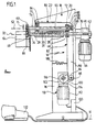
- the head part 18 is firmly connected to the stand 16 and points from its above the stand 16 arranged base 20 a laterally above the stand 16th projection 22 extending beyond.
- first tool shaft 30 is above the End 28 of the bearing sleeve 24 with a front end 34 over and carries a first rolling tool 40, which is non-rotatable is connected to the first tool shaft 30.
- first tool shaft 30 extends through the Bearing sleeve 24 through and thus also through the projection 22nd and the base 20 of the head portion 18 through and on one of the Cantilever 22 opposite side over the stand 16 and the head part 18 out to a rear end 36, which by a drive designated as a whole by 42, preferably an electric drive motor 44 with a Reduction gear 46, can be driven.
- first tool shaft 30 also carries an intermediate pinion 48, which in the region of the base 20 of the head part 18 between the bearing sleeve 24 and the rear end 36 is arranged and with which a second tool shaft 50 is drivable, the one on the stand 16 opposite Side of the first tool shaft 30 is and around second roll axis 52 is rotatable.
- the second tool shaft 50 also extends over the Cantilever 22 of the head portion 18 and carries on front end 54, a second rolling tool 60, which with the first rolling tool 40 in the sense of rolling sheet metal processing of a workpiece 64 interacts, for example to provide the workpiece 64 with a bead 66.
- the second tool shaft 50 also extends into the Head part 18 and through the projection 22 to the base 20 and ends in the base 20 area a rear end 56.
- the second tool shaft 50 is rotatably supported on the one hand by a in the area of the rear end 56 arranged rear side opposite the machine frame 10 pivotally mounted pivot bearing 68 and a near the front end 54 arranged delivery bearing 70, which in Distance from the second rolling tool 60, preferably arranged approximately over the end region 28 of the bearing sleeve 24 is.
- a drive is close to driving the second tool shaft 50 the rear pivot bearing 68, preferably immediately next to this, arranged intermediate pinion 72 is provided, which is in direct engagement with the intermediate pinion 48 stands.
- the drive 42 first drives the first tool shaft 30 and via the intermediate pinions 48 and 72 driving derived from the first tool shaft 30 the second tool shaft 50.
- first arm 80 of a lever gear designated 82 provided, which at a front end 84 delivery bearings arranged in the projection 22 of the head part 18 70 carries and starting from its front end 84 the projection 22 to the base 20 of the head part 18th extends. That arranged in the area of a rear end 86 the rear pivot bearing 68 for the second tool shaft 50 is either independently pivotable on the machine frame 10 stored or held at the rear end 86 and with the Arm 80 swiveling. Furthermore, the first arm 80 is in the area of the rear end 86 about a pivot axis 88 by means of journals 89 in the area of the base 20 of the head part 18 on the machine frame 10 pivoted.
- the pivot axis 88 is preferably close to the rear Pivot bearing 68 and the intermediate pinion 72, preferably right next to these or enforces them, so that the pivoting movement of the first arm 80 about the pivot axis 88 to reach different delivery positions of the second rolling tool 60 so that the intermediate pinion 72 always remains in engagement with the intermediate pinion 48 and thus always the rotational movement of the second tool shaft 50 coupled with the rotational movement of the first tool shaft 30 remains.
- the lever gear 82 further includes a rigid with the first Arm 80 connected second arm 90, which is based on whose rear end 86 extends in the direction of the foot part 12 and is preferably arranged within the stand 16 and at its end 94 facing away from the pivot axis 88 a curve follower 96 in the form of a rotatable on an axis 99 stored role.
- the curve follower 96 lies at one by one relative to the Stand 16 fixed axis of rotation 98 rotatable with respect to the stator 16 mounted cam 100 one which is located radially outside of the axis of rotation 98 and is spiral to the axis of rotation 98 extending trajectory 102 carries, so that accordingly the rotational position of the cam 100 of the cam followers 96 at different distances from the axis of rotation 98 is positionable.
- the cam plate 100 is included as a whole 110 designated feed drive, which preferably has an electric motor 112 and a transmission 114.
- the second arm 90 is by means of an elastic Energy storage 116, which acts on the one hand on the stand 16 and on the other hand always on the second arm 90 by an elastic Force is applied to curve follower 96 on the trajectory 102 is present.
- the cam 100 by the feed drive 110th rotated the distance of the curve follower 96 from the Axis of rotation 98 can be varied and thus the second arm 90 is due its pivotability about the pivot axis 88 compared to the Machine frame 10 pivotable, resulting in the simultaneous
- the first arm 80 can also be pivoted to the machine frame 10, in particular relative to the head part 18, results.
- the curve follower 96 is now relative to the cam 100 arranged that an increase in the distance of the curve follower 96 from the axis of rotation 98 to a delivery of the Feed bearing 70 leads in the direction of the first roll axis 32, that is to a delivery of the second rolling tool 60 in Direction of the first rolling tool 40.
- the first arm 80 and the second arm 90 are of the Lever gear 82 each consisting of two cheek parts 80a and 80b or 90a and 90b, between which the delivery bearing 70 and the rear pivot bearing 68 of the second tool shaft 50 lie and each in turn on the bearing pin 89a and 89b on the machine frame 10 in the area of the base 20 of the Headboard are stored. Furthermore, the cheek parts 90a and 90b connected by an axis 99, on which the curve follower 96 is rotatably supported.
- a controller designated as a whole with 120 is provided, which, as shown in Fig. 3, a central processor 122, with which on the one hand a controller 124 for the Infeed drive 110 and on the other hand a controller 126 for the Roll drive 42 controllable.
- the positioning drive 110 is a position transmitter 128 assigned and the roller drive 42, a position transmitter 130, the can also be queried via the central processor 122.
- the central processor 122 are also external Foot switch 132 the desired speed for the rolling movement, that is, predeterminable and for the roller drive 42 a manual control panel 134, for example shown in FIG. 4, by means of a manually adjustable via a rotary knob 136 Encoder 138 the delivery position of the second rolling tool 60. Furthermore, a switch field 140 is provided, which one Switch 142 for switching between two opposite ones Direction of rotation of the roller drive 42, a switch 144 to switch between fast and slow running of the Roller drive 42 and two switches 146 and 148 for retraining from manual mode to learning mode or manual mode operation of the delivery positions controlled by the controller 120, as explained in detail below.
- the central processor 122 has a memory 150 assigned in which data records 152 can be stored, in which individual roll axis positions R, delivery positions Z and movement direction information BR of the roll axis movement assigned.
- an exemplary workpiece becomes 64 processed in a forming cycle, whereby by the Foot switch 132 and the one adjustable by switch 144 slow motion mode with the individual roll axis positions approached at low speed and additionally with the encoder 138 manually set the desired delivery positions so that the central processor 122 in the Is able, on the one hand via the position transmitter 130 and the Position encoder 128 the roll axis positions and the delivery positions in addition to information about the direction of movement to detect the roll axis movement and in the memory 150 as data records 152.
- the central processor 122 can now execute in the memory 150 the data records 152 correspond to the respective roll axis positions R assigned delivery positions Z and the corresponding Determine direction of movement BR so that the central processor 122 is able to control the feed drive 110 in such a way that the second rolling tool 60 in the corresponding Roll axis positions R in the stored feed positions Z stands and also the roller drive 42 in the desired Direction of movement BR runs.
- Such a forming cycle is shown in FIG. 5, for example shown.
- the infeed position Z1 assigned to the roll axis position R0 approached.
- the roll axis drive 42 of the central processor 122 started and at the same time the Feed drive 110 controlled so that in the roll axis position R1 the second rolling tool 60 in the delivery position Z2 stands.
- the roller axle drive is in this infeed position 42 continued to operate until the roll axis position R2.
- control is activated again of the feed drive 110, in such a way that when reached the roll axis position R3 has reached the infeed position Z3.
- the roll axis drive continues in this infeed position Z3 42 controlled, up to a roll axis position R4 and starting with the roll axis position R4 being reached Feed drive 110 driven again so that the When the roll axis position R5 is reached the delivery position Z4 is reached.
- the roll axis position R5 controlled simultaneously by the central processor 122 Change of direction of movement BR0 of the roll axis drive so that this moves in the reverse direction BR1 again until the roll axis position R6 is reached.
- the roll axis position R6 After the roll axis position R6 has been reached, another takes place Control the feed drive 110 so that when the Roll axis position R7 the infeed position Z5 is reached.
- a speed limit mode is provided which the Speed of the roll axis movement deviates from that of Foot switch 132 provided maximum speed changed, if the central processor 122 due to the known Response times of the feed drive 110 recognize that the delivery positions Z stored in the data records 152 at the corresponding roll axis positions cannot be reached can.
- the central processor 122 the speed of the roller drive 42 so far that the speed of the infeed movement can follow the individual roll axis positions and thus the maintain correspondence corresponding to records 152 can be.
- the central processor 122 preferably works Records 152 look ahead, that is, if a certain roll axis position RX has already been reached by the central processor 122 records 152 are analyzed, the future roll axis positions correspond to RX + ⁇ , so that a forward-looking decision can be made as to whether a Reduction of the speed of the roller drive 42 deviating from that specified by foot switch 132 maximum speed is required to complete the mapping the delivery positions Z to the roll axis positions R upright to receive or in a future roll axis position R to be able to reverse the direction of what inevitably a reduction in the speed of the Roll axis movement to zero and subsequent acceleration requires.
- the speed limit mode is preferred designed to limit the Speed corresponding to a central processor 122 predetermined fixed value takes place.
Landscapes
- Engineering & Computer Science (AREA)
- Mechanical Engineering (AREA)
- Bending Of Plates, Rods, And Pipes (AREA)
- Powder Metallurgy (AREA)
- Diaphragms For Electromechanical Transducers (AREA)
- Press Drives And Press Lines (AREA)
- Mechanical Treatment Of Semiconductor (AREA)
- Golf Clubs (AREA)
- Winding Of Webs (AREA)
Claims (32)
- Dispositif pour le formage de tôles comprenant un bâti de machine (10), un premier outil de roulage (40) placé sur le bâti de machine (10) de manière à pouvoir tourner autour d'un premier axe de roulage (32), un deuxième outil de roulage (60) placé de manière à pouvoir tourner autour d'un deuxième axe de roulage (52) et coopérant avec le premier outil de roulage (40) qui est placé de manière à pouvoir tourner sur un palier d'avance (70) qui, de son côté, peut être déplacé et fixé par rapport au bâti de machine (10) transversalement à un premier axe de roulage (32) au moyen d'un entraínement d'avance (110) de telle sorte qu'une position d'avance (Z) du deuxième outil de roulage (60) peut être ajustée par rapport au premier outil de roulage (40), et un entraínement de roulage (42) pour au moins d'un des axes de roulage (32, 52),
caractérisé en ce que l'entraínement d'avance (110) est conformé comme un entraínement d'avance dont la position peut être commandée par une commande (120) et au moyen duquel le deuxième outil de roulage (60) peut être déplacé dans des positions d'avance (Z) définies au préalable, en ce que l'entraínement de roulage (42) est confirmé comme un entraínement de roulage pouvant être commandé et ce qu'avec la commande (120), les positions (R) des axes de roulage (32, 52) peuvent être détectées, et les positions (R) des axes de roulage et les positions d'avance (Z) peuvent être liées ensemble. - Machine pour le formage de tôles selon la revendication 1, caractérisée en ce que la commande (120) coordonne des positions d'avance (Z) aux positions (R) des axes de roulage et stocke celles-ci comme blocs de données (152) dans une mémoire (150).
- Machine pour le formage de tôles selon la revendication 2, caractérisée en ce que des blocs de données (152) pour au moins un cycle de formage d'une pièce à usiner (64) peuvent être stockés dans la mémoire (150).
- Machine pour le formage de tôles selon une des revendications précédentes, caractérisée en ce que la commande (120) enregistre dans un mode d'apprentissage une coordination de positions d'avance (Z) avec les positions (R) des axes de roulage.
- Machine pour le formage de tôles selon la revendication 4, caractérisée en ce que la coordination de positions d'avance (Z) et de positions (R) des axes de roulage peut être enregistrée par la commande (120) au cours d'un cycle de formage commandé manuellement, exécuté effectivement avec la machine pour le formage de tôles sur une pièce à usiner (64).
- Machine pour le formage de tôles selon une des revendications précédentes, caractérisée en ce qu'avec la commande (120) dans un mode de formage, un formage commandé d'une pièce à usiner (64) peut être exécuté, dans lequel la commande (120) realise automatiquement, en lisant les données stockées, la coordination mémorisée des positions d'avance (Z) avec les positions des axas de roulage (R) en commandant l'entraínement d'avance (110).
- Machine pour le formage de tôles selon la revendication 6, caractérisée en ce que dans le mode de formage, la vitesse maximale du mouvement des axes de roulage peu être prédéterminée manuellement lors du formage.
- Machine pour le formage de tôles selon la revendication 6 ou 7, caractérisée en ce que la commande (120) dispose d'un mode de limitation de la vitesse dans lequel avec la commande (120) dans le mode de formage, la vitesse maximale possible du mouvement des axes de roulage peut être réglée de manière à être différente de la vitesse manuellement prédéterminée du mouvement des axes de roulage.
- Machine pour le formage de tôles selon la revendication 8, caractérisée en ce que la commande (120) passe dans le mode de limitation de la vitesse, quand un mouvement d'avance doit avoir lieu.
- Machine pour le formage de tôles selon la revendication 8 ou 9, caractérisée en ce que la commande (120) dans le mode de limitation de la vitesse adapte la vitesse maximale possible du mouvement des axes de roulage à la vitesse maximale possible du mouvement d'avance de telle manière que la coordination de la position d'avance (Z) et de la position (R) des axes de roulage soit maintenue.
- Machine pour le formage de tôles selon une des revendications précédentes, caractérisée en ce que des informations (BR) sur le mouvement des axes de roulage peuvent être mémorisées avec la commande (120).
- Machine pour le formage de tôles selon la revendication 11, caractérisée en ce que les informations (BR) sur le mouvement des axes de roulage sont coordonnées aux positions (R) des axes de roulage.
- Machine pour le formage de tôles selon la revendication 11 ou 12, caractérisée en ce que les informations (BR) sur le mouvement des axes de roulage sont enregistrées dans les blocs de données (152) comprenant les positions (R) des axes de roulage et les positions d'avance (Z).
- Machine pour le formage de tôles selon une des revendications 11 à 13, caractérisée en ce que les informations sur le mouvement des axes de roulage sont des informations sur le sens de mouvement (BR) des axes de roulage.
- Machine pour le formage de tôles selon une des revendications 11 à 14, caractérisée en ce que la commande (120) passe dans le mode de limitation de la vitesse, quand un changement de sens du mouvement (BR) des axes de roulage doit avoir lieu.
- Machine pour le formage de tôles selon la revendication 15, caractérisée en ce que la commande (120) dans le mode de limitation de la vitesse réduit à zéro, lors d'une modification du sens de mouvement (BR) des axes de roulage, la vitesse du mouvement des axes de roulage selon une allure prédéterminée et ensuite l'augmente à nouveau en sens inverse selon une allure prédéterminée.
- Machine pour le formage de tôles selon une des revendications précédentes, caractérisée en ce que la commande (120) enregistre les informations coordonnées aux futures positions des axes de roulage en partant de la position des axes de roulage du moment.
- Machine pour le formage de tôles selon la revendication 17, caractérisée en ce que la commande (120) passe dans le mode de limitation de la vitesse en raison des informations coordonnées aux futures positions (R) des axes de roulage.
- Machine pour le formage de tôles selon le préambule de la revendication 1 ou selon une des revendications précédentes, dans laquelle le bâti de machine (10) comprend un statif (16) avec une pièce de tête (18) disposée sur celui-ci, le premier outil de roulage (40) est placé dans la pièce de tête (18) de manière à tourner autour du premier axe de roulage (32) et le palier d'avance (70) pour le deuxième outil de roulage (60) est disposé dans la pièce de tête (18), caractérisée en ce que le palier d'avance (70) est placé dans une région extrême (84) orientée vers les outils de roulage (40, 60) d'un bras (80) s'étendant dans la pièce de tête (18) et en ce que l'entraínement d'avance (70) est disposé sur le bâti (10) de machine en dehors d'une saillie (22) de la pièce de tête (18) et agit sur le bras (80).
- Machine pour le formage de tôles selon la revendication 19, caractérisée en ce que le bras (80) fait partie d'un mécanisme à levier (82) qui peut être actionné par l'entraínement d'avance (110).
- Machine pour le formage de tôles selon la revendication 20, caractérisée en ce que le mécanisme à levier (82) est placé sur le bâti (10) de machine par le biais d'un axe de palier (88) qui est disposé à distance des outils de roulage (40, 60).
- Machine pour le formage de tôles selon la revendication 21, caractérisée en ce que l'axe de palier (88) est disposé en dehors de la saillie (22) de la pièce de tête (18).
- Machine pour le formage de tôles selon la revendication 21 ou 22, caractérisée en ce que l'axe de palier (88) est disposé dans une région du bâti (10) de la machine opposée aux outils de roulage (40, 60).
- Machine pour le formage de tôles selon la revendication 22 ou 23, caractérisée en ce que l'axe de palier (88) est disposé dans la base (20) de la pièce de tête (18).
- Machine pour le formage de tôles selon une des revendications 20 à 24, caractérisée en ce que le mécanisme à levier (82) présente un deuxième bras (90) sur lequel l'entraínement d'avance (110) agit.
- Machine pour le formage de tôles selon la revendication 25, caractérisée en ce que le deuxième bras (90) s'étend en direction du statif (16).
- Machine pour le formage de tôles selon une des revendications 19 à 26, caractérisée en ce que l'entraínement d'avance (110) agit sur le premier bras par l'intermédiaire d'un mécanisme démultiplicateur (96, 100).
- Machine pour le formage de tôles selon la revendication 27, caractérisée en ce que le mécanisme démultiplicateur comporte un mécanisme à cannelures (96, 100).
- Machine pour le formage de tôles selon la revendication 28, caractérisée en ce que le mécanisme à cannelures est conformé comme un mécanisme à came (96, 100).
- Machine pour le formage de tôles selon la revendication 29, caractérisée en ce que le mécanisme à came présente un disque à came (100) qui agit sur un galet de came (96) dans le sens d'une avance du deuxième outil de roulage (60) vers le premier outil de roulage (40).
- Machine pour le formage de tôles selon la revendication 29, caractérisée en ce qu'il est prévu un accumulateur d'énergie (116) élastique qui agit sur le premier bras (80) dans le sens d'un mouvement du deuxième outil de roulage (60) par rapport au premier outil de roulage (40) en sens inverse à la direction d'avance.
- Machine pour le formage de tôles selon une des revendications 20 à 31, caractérisée en ce que le mécanisme à levier (82) comprend un levier coudé qui s'étend avec le premier bras (80) dans la pièce de tête (18) et avec le deuxième bras (90) dans le statif (16).
Applications Claiming Priority (3)
| Application Number | Priority Date | Filing Date | Title |
|---|---|---|---|
| DE10013801A DE10013801A1 (de) | 2000-03-20 | 2000-03-20 | Blechumformmaschine |
| DE10013801 | 2000-03-20 | ||
| PCT/EP2001/002595 WO2001070427A1 (fr) | 2000-03-20 | 2001-03-08 | Machine pour le formage de tole |
Publications (2)
| Publication Number | Publication Date |
|---|---|
| EP1178864A1 EP1178864A1 (fr) | 2002-02-13 |
| EP1178864B1 true EP1178864B1 (fr) | 2003-07-09 |
Family
ID=7635650
Family Applications (1)
| Application Number | Title | Priority Date | Filing Date |
|---|---|---|---|
| EP01917079A Expired - Lifetime EP1178864B1 (fr) | 2000-03-20 | 2001-03-08 | Machine pour le formage de tole |
Country Status (10)
| Country | Link |
|---|---|
| US (1) | US6591651B2 (fr) |
| EP (1) | EP1178864B1 (fr) |
| JP (1) | JP2003527970A (fr) |
| AT (1) | ATE244612T1 (fr) |
| CA (1) | CA2374400A1 (fr) |
| DE (2) | DE10013801A1 (fr) |
| DK (1) | DK1178864T3 (fr) |
| ES (1) | ES2202284T3 (fr) |
| PT (1) | PT1178864E (fr) |
| WO (1) | WO2001070427A1 (fr) |
Families Citing this family (15)
| Publication number | Priority date | Publication date | Assignee | Title |
|---|---|---|---|---|
| NL1016348C2 (nl) | 2000-07-21 | 2002-01-22 | Johan Massue | Werkwijze en forceermachine voor het vervormen van een hol werkstuk. |
| NL1015773C2 (nl) * | 2000-07-21 | 2002-01-22 | Johan Massue | Werkwijze en inrichting voor het vervormen van een hol werkstuk. |
| DE10209154A1 (de) * | 2002-03-01 | 2003-09-11 | Sig Cantec Gmbh & Co Kg | Vorrichtung zum Umformen und/oder Falzen von Dosenzargen |
| EP1724033B1 (fr) † | 2003-09-25 | 2008-03-19 | Mabi Ag | Machine pour réaliser des nervures, bords et analogues dans des tôles |
| JP2007021547A (ja) * | 2005-07-19 | 2007-02-01 | Asano:Kk | パイプ加工装置 |
| US7536889B1 (en) * | 2006-08-04 | 2009-05-26 | Mueller Thomas L | Rotary rolling machine |
| TWI341554B (en) * | 2007-08-02 | 2011-05-01 | Enthone | Copper metallization of through silicon via |
| CN101862778B (zh) * | 2009-04-16 | 2012-05-30 | 杨岩顺 | 旋转折叠式液压滚槽机 |
| AT510949B1 (de) * | 2010-12-17 | 2015-07-15 | Trumpf Maschinen Austria Gmbh | Steuer- und regelvorrichtung für eine biegepresse |
| SE1100430A1 (sv) | 2011-06-01 | 2012-10-02 | Jansson Lars | Sick- och falsmaskin |
| DE102013105468B4 (de) * | 2013-05-28 | 2015-10-01 | Schuler Pressen Gmbh | Verfahren zur Steuerung einer Presse mit variabler Getriebeübersetzung |
| US9333548B2 (en) * | 2013-08-12 | 2016-05-10 | Victaulic Company | Method and device for forming grooves in pipe elements |
| EP3706931A1 (fr) * | 2017-11-10 | 2020-09-16 | Promau S.r.l. | Appareil et procédé de support et d'avancement commandé d'une feuille métallique dans une machine à cintrer permettant d'obtenir des structures cylindriques ou de cône tronqué |
| CN112872227B (zh) * | 2021-01-12 | 2025-06-13 | 三一汽车制造有限公司 | 拼装式筒体生产线及生产方法 |
| US20230058084A1 (en) * | 2021-08-19 | 2023-02-23 | Milwaukee Electric Tool Corporation | Tool and method for roll grooving a workpiece |
Family Cites Families (10)
| Publication number | Priority date | Publication date | Assignee | Title |
|---|---|---|---|---|
| DE843536C (de) * | 1950-08-29 | 1952-07-10 | Theo Dr-Ing Krueckels | Sickenmaschine |
| DE1089714B (de) * | 1956-09-27 | 1960-09-29 | Karl Hundhausen | Maschine zum Sicken, Boerdeln, Schneiden und Biegen von Blechen, Rohren und Profilen |
| CH492489A (de) * | 1968-05-21 | 1970-06-30 | Chr Haeusler Fa | Bördelmaschine zum Bördeln von Kesselböden |
| NL173488C (nl) * | 1981-03-13 | 1984-02-01 | Fontijne Bv Machine | Velgprofileerinrichting. |
| IT1178379B (it) * | 1983-08-04 | 1987-09-09 | Hurth Masch Zahnrad Carl | Dispositivo di posizionamento di un carrello di macchina utensile rispetto ad una parte fissa della macchina |
| IT1234881B (it) * | 1988-02-25 | 1992-06-02 | Danieli Off Mecc | Gabbia con rulli a sbalzo ad assi angolati. |
| US4869088A (en) * | 1988-07-05 | 1989-09-26 | Kazuo Kadotani | Ring shaping apparatus |
| DE3936200C1 (fr) * | 1989-10-31 | 1990-12-13 | Leifeld Gmbh & Co, 4730 Ahlen, De | |
| EP0477752B1 (fr) * | 1990-09-28 | 1995-03-29 | Promau S.R.L. | Dispositif programmable pour rouler les tôles |
| JPH11342440A (ja) * | 1998-05-28 | 1999-12-14 | Nippon Seiko Kk | 工具制御装置 |
-
2000
- 2000-03-20 DE DE10013801A patent/DE10013801A1/de not_active Ceased
-
2001
- 2001-03-08 DK DK01917079T patent/DK1178864T3/da active
- 2001-03-08 EP EP01917079A patent/EP1178864B1/fr not_active Expired - Lifetime
- 2001-03-08 AT AT01917079T patent/ATE244612T1/de active
- 2001-03-08 ES ES01917079T patent/ES2202284T3/es not_active Expired - Lifetime
- 2001-03-08 PT PT01917079T patent/PT1178864E/pt unknown
- 2001-03-08 WO PCT/EP2001/002595 patent/WO2001070427A1/fr not_active Ceased
- 2001-03-08 DE DE50100359T patent/DE50100359D1/de not_active Expired - Lifetime
- 2001-03-08 JP JP2001568611A patent/JP2003527970A/ja active Pending
- 2001-03-08 CA CA002374400A patent/CA2374400A1/fr not_active Abandoned
- 2001-11-19 US US09/996,031 patent/US6591651B2/en not_active Expired - Fee Related
Also Published As
| Publication number | Publication date |
|---|---|
| US6591651B2 (en) | 2003-07-15 |
| DK1178864T3 (da) | 2003-10-27 |
| DE10013801A1 (de) | 2001-10-18 |
| DE50100359D1 (de) | 2003-08-14 |
| ES2202284T3 (es) | 2004-04-01 |
| CA2374400A1 (fr) | 2001-09-27 |
| PT1178864E (pt) | 2003-11-28 |
| ATE244612T1 (de) | 2003-07-15 |
| EP1178864A1 (fr) | 2002-02-13 |
| US20020083750A1 (en) | 2002-07-04 |
| WO2001070427A1 (fr) | 2001-09-27 |
| JP2003527970A (ja) | 2003-09-24 |
Similar Documents
| Publication | Publication Date | Title |
|---|---|---|
| EP1178864B1 (fr) | Machine pour le formage de tole | |
| DE2721553C3 (de) | Maschine zum Schleifen und Polieren von Werkstücken mit sphärischer Oberfläche, insbesondere von Linsen | |
| DE2837368C2 (de) | Honmaschine | |
| DE3017613C2 (fr) | ||
| CH636034A5 (de) | Abrichtgeraet fuer eine tellerfoermige schleifscheibe an einer zahnflankenschleifmaschine. | |
| EP0881041B1 (fr) | Machine d'écrouissage pour vilbrequins | |
| EP0949021B1 (fr) | Dispositif pour le formage de fil ayant un dispositif de freinage de fil | |
| DE3441530A1 (de) | Aufnahmeeinrichtung fuer das werkzeug einer schneidpresse | |
| DE19904253A1 (de) | Werkzeugmaschine | |
| DE2505985C3 (de) | Sägenschärfmaschine zum Schärfen von Zähnen unterschiedlicher Zahnspitzenhöhe | |
| EP1724033A2 (fr) | Machine pour réaliser des nervures, bords et analogues dans des tôles | |
| DE69702860T2 (de) | Vorrichtung zum verschieben eines teils einer maschine und ausüben einer kraft am bewegungsende | |
| WO2004033124A1 (fr) | Machine a cintrer | |
| DE1901325C3 (de) | Fräsmaschine zur Nachformbearbeitung von sich drehenden Werkstücken | |
| DE2752709A1 (de) | Farbbeschichtungsmaschine | |
| DE1452733B2 (de) | Maschine zum Zuschneiden und Sieken von zylindrischen Dosen | |
| EP1257372A1 (fr) | Dispositif de pliage destine a un materiau bande plastiquement deformable | |
| DE2737598A1 (de) | Zahnrad-bearbeitungsmaschine fuer stirnkanten von zahnraedern | |
| EP0818253A2 (fr) | Poinçonneuse à revolver | |
| DE952486C (de) | Universalwerkzeugmaschine | |
| DE19913087A1 (de) | Antriebseinrichtung zum Einstellen der Winkellage der Messer eines Pendelschnittwerkzeuges | |
| DE1911696A1 (de) | Werkzeugueberfuehrungsvorrichtung fuer automatische Werkzeugmaschinen | |
| DE1935804A1 (de) | Vorschubantrieb fuer Werkzeugmaschinenschlitten mit numerisch gesteuertem elektrischen Schrittmotor und hydraulischem Verstaerker | |
| DE1502090C (de) | Konturenfräsvorrichtung | |
| DE2044379A1 (de) | Vorrichtung zum spanabhebenden Abrunden der Zahnenden von Zahnrädern |
Legal Events
| Date | Code | Title | Description |
|---|---|---|---|
| PUAI | Public reference made under article 153(3) epc to a published international application that has entered the european phase |
Free format text: ORIGINAL CODE: 0009012 |
|
| 17P | Request for examination filed |
Effective date: 20011130 |
|
| AK | Designated contracting states |
Kind code of ref document: A1 Designated state(s): AT BE CH CY DE DK ES FI FR GB GR IE IT LI LU MC NL PT SE TR |
|
| AX | Request for extension of the european patent |
Free format text: AL;LT;LV;MK;RO;SI |
|
| GRAG | Despatch of communication of intention to grant |
Free format text: ORIGINAL CODE: EPIDOS AGRA |
|
| 17Q | First examination report despatched |
Effective date: 20020603 |
|
| GRAG | Despatch of communication of intention to grant |
Free format text: ORIGINAL CODE: EPIDOS AGRA |
|
| GRAH | Despatch of communication of intention to grant a patent |
Free format text: ORIGINAL CODE: EPIDOS IGRA |
|
| GRAH | Despatch of communication of intention to grant a patent |
Free format text: ORIGINAL CODE: EPIDOS IGRA |
|
| GRAA | (expected) grant |
Free format text: ORIGINAL CODE: 0009210 |
|
| AK | Designated contracting states |
Designated state(s): AT BE CH CY DE DK ES FI FR GB GR IE IT LI LU MC NL PT SE TR |
|
| PG25 | Lapsed in a contracting state [announced via postgrant information from national office to epo] |
Ref country code: CY Free format text: LAPSE BECAUSE OF FAILURE TO SUBMIT A TRANSLATION OF THE DESCRIPTION OR TO PAY THE FEE WITHIN THE PRESCRIBED TIME-LIMIT Effective date: 20030709 |
|
| REG | Reference to a national code |
Ref country code: GB Ref legal event code: FG4D Free format text: NOT ENGLISH |
|
| REG | Reference to a national code |
Ref country code: CH Ref legal event code: EP |
|
| REF | Corresponds to: |
Ref document number: 50100359 Country of ref document: DE Date of ref document: 20030814 Kind code of ref document: P |
|
| REG | Reference to a national code |
Ref country code: CH Ref legal event code: NV Representative=s name: KIRKER & CIE SA |
|
| REG | Reference to a national code |
Ref country code: IE Ref legal event code: FG4D Free format text: GERMAN |
|
| REG | Reference to a national code |
Ref country code: GR Ref legal event code: EP Ref document number: 20030403841 Country of ref document: GR |
|
| REG | Reference to a national code |
Ref country code: SE Ref legal event code: TRGR |
|
| GBT | Gb: translation of ep patent filed (gb section 77(6)(a)/1977) |
Effective date: 20031110 |
|
| LTIE | Lt: invalidation of european patent or patent extension |
Effective date: 20030709 |
|
| PG25 | Lapsed in a contracting state [announced via postgrant information from national office to epo] |
Ref country code: LU Free format text: LAPSE BECAUSE OF NON-PAYMENT OF DUE FEES Effective date: 20040308 |
|
| PG25 | Lapsed in a contracting state [announced via postgrant information from national office to epo] |
Ref country code: MC Free format text: LAPSE BECAUSE OF NON-PAYMENT OF DUE FEES Effective date: 20040331 |
|
| REG | Reference to a national code |
Ref country code: ES Ref legal event code: FG2A Ref document number: 2202284 Country of ref document: ES Kind code of ref document: T3 |
|
| ET | Fr: translation filed | ||
| PLBE | No opposition filed within time limit |
Free format text: ORIGINAL CODE: 0009261 |
|
| STAA | Information on the status of an ep patent application or granted ep patent |
Free format text: STATUS: NO OPPOSITION FILED WITHIN TIME LIMIT |
|
| 26N | No opposition filed |
Effective date: 20040414 |
|
| PGFP | Annual fee paid to national office [announced via postgrant information from national office to epo] |
Ref country code: IE Payment date: 20090227 Year of fee payment: 9 |
|
| PGFP | Annual fee paid to national office [announced via postgrant information from national office to epo] |
Ref country code: PT Payment date: 20090122 Year of fee payment: 9 |
|
| PGFP | Annual fee paid to national office [announced via postgrant information from national office to epo] |
Ref country code: GB Payment date: 20090120 Year of fee payment: 9 Ref country code: GR Payment date: 20090123 Year of fee payment: 9 |
|
| REG | Reference to a national code |
Ref country code: PT Ref legal event code: MM4A Free format text: LAPSE DUE TO NON-PAYMENT OF FEES Effective date: 20100908 |
|
| GBPC | Gb: european patent ceased through non-payment of renewal fee |
Effective date: 20100308 |
|
| REG | Reference to a national code |
Ref country code: IE Ref legal event code: MM4A |
|
| PG25 | Lapsed in a contracting state [announced via postgrant information from national office to epo] |
Ref country code: IE Free format text: LAPSE BECAUSE OF NON-PAYMENT OF DUE FEES Effective date: 20100308 Ref country code: PT Free format text: LAPSE BECAUSE OF NON-PAYMENT OF DUE FEES Effective date: 20100908 |
|
| PG25 | Lapsed in a contracting state [announced via postgrant information from national office to epo] |
Ref country code: GR Free format text: LAPSE BECAUSE OF NON-PAYMENT OF DUE FEES Effective date: 20101004 Ref country code: GB Free format text: LAPSE BECAUSE OF NON-PAYMENT OF DUE FEES Effective date: 20100308 |
|
| PGFP | Annual fee paid to national office [announced via postgrant information from national office to epo] |
Ref country code: SE Payment date: 20130312 Year of fee payment: 13 Ref country code: DK Payment date: 20130312 Year of fee payment: 13 Ref country code: FI Payment date: 20130312 Year of fee payment: 13 Ref country code: ES Payment date: 20130313 Year of fee payment: 13 |
|
| PGFP | Annual fee paid to national office [announced via postgrant information from national office to epo] |
Ref country code: NL Payment date: 20130309 Year of fee payment: 13 |
|
| PGFP | Annual fee paid to national office [announced via postgrant information from national office to epo] |
Ref country code: AT Payment date: 20130226 Year of fee payment: 13 |
|
| PGFP | Annual fee paid to national office [announced via postgrant information from national office to epo] |
Ref country code: BE Payment date: 20130312 Year of fee payment: 13 |
|
| REG | Reference to a national code |
Ref country code: DK Ref legal event code: EBP Effective date: 20140331 |
|
| REG | Reference to a national code |
Ref country code: NL Ref legal event code: V1 Effective date: 20141001 |
|
| PG25 | Lapsed in a contracting state [announced via postgrant information from national office to epo] |
Ref country code: FI Free format text: LAPSE BECAUSE OF NON-PAYMENT OF DUE FEES Effective date: 20140308 |
|
| REG | Reference to a national code |
Ref country code: SE Ref legal event code: EUG |
|
| REG | Reference to a national code |
Ref country code: AT Ref legal event code: MM01 Ref document number: 244612 Country of ref document: AT Kind code of ref document: T Effective date: 20140308 |
|
| PG25 | Lapsed in a contracting state [announced via postgrant information from national office to epo] |
Ref country code: SE Free format text: LAPSE BECAUSE OF NON-PAYMENT OF DUE FEES Effective date: 20140309 |
|
| PG25 | Lapsed in a contracting state [announced via postgrant information from national office to epo] |
Ref country code: NL Free format text: LAPSE BECAUSE OF NON-PAYMENT OF DUE FEES Effective date: 20141001 Ref country code: AT Free format text: LAPSE BECAUSE OF NON-PAYMENT OF DUE FEES Effective date: 20140308 |
|
| REG | Reference to a national code |
Ref country code: ES Ref legal event code: FD2A Effective date: 20150428 |
|
| PG25 | Lapsed in a contracting state [announced via postgrant information from national office to epo] |
Ref country code: DK Free format text: LAPSE BECAUSE OF NON-PAYMENT OF DUE FEES Effective date: 20140331 |
|
| REG | Reference to a national code |
Ref country code: DE Ref legal event code: R082 Ref document number: 50100359 Country of ref document: DE Representative=s name: HOEGER, STELLRECHT & PARTNER PATENTANWAELTE MB, DE |
|
| PG25 | Lapsed in a contracting state [announced via postgrant information from national office to epo] |
Ref country code: ES Free format text: LAPSE BECAUSE OF NON-PAYMENT OF DUE FEES Effective date: 20140309 |
|
| REG | Reference to a national code |
Ref country code: FR Ref legal event code: PLFP Year of fee payment: 16 |
|
| PGFP | Annual fee paid to national office [announced via postgrant information from national office to epo] |
Ref country code: TR Payment date: 20160127 Year of fee payment: 16 |
|
| REG | Reference to a national code |
Ref country code: FR Ref legal event code: PLFP Year of fee payment: 17 |
|
| PG25 | Lapsed in a contracting state [announced via postgrant information from national office to epo] |
Ref country code: BE Free format text: LAPSE BECAUSE OF NON-PAYMENT OF DUE FEES Effective date: 20140331 |
|
| REG | Reference to a national code |
Ref country code: FR Ref legal event code: PLFP Year of fee payment: 18 |
|
| REG | Reference to a national code |
Ref country code: DE Ref legal event code: R082 Ref document number: 50100359 Country of ref document: DE Representative=s name: HOEGER, STELLRECHT & PARTNER PATENTANWAELTE MB, DE |
|
| PGFP | Annual fee paid to national office [announced via postgrant information from national office to epo] |
Ref country code: IT Payment date: 20200221 Year of fee payment: 20 Ref country code: DE Payment date: 20200326 Year of fee payment: 20 |
|
| PGFP | Annual fee paid to national office [announced via postgrant information from national office to epo] |
Ref country code: CH Payment date: 20200313 Year of fee payment: 20 |
|
| PGFP | Annual fee paid to national office [announced via postgrant information from national office to epo] |
Ref country code: FR Payment date: 20200214 Year of fee payment: 20 |
|
| REG | Reference to a national code |
Ref country code: DE Ref legal event code: R071 Ref document number: 50100359 Country of ref document: DE |
|
| REG | Reference to a national code |
Ref country code: CH Ref legal event code: PL |
|
| PG25 | Lapsed in a contracting state [announced via postgrant information from national office to epo] |
Ref country code: TR Free format text: LAPSE BECAUSE OF NON-PAYMENT OF DUE FEES Effective date: 20170308 |