EP1179112B1 - Agencement de profiles pour l'interruption d'un pont thermoconducteur entre un cote interieur et un cote exterieur - Google Patents
Agencement de profiles pour l'interruption d'un pont thermoconducteur entre un cote interieur et un cote exterieur Download PDFInfo
- Publication number
- EP1179112B1 EP1179112B1 EP00936751A EP00936751A EP1179112B1 EP 1179112 B1 EP1179112 B1 EP 1179112B1 EP 00936751 A EP00936751 A EP 00936751A EP 00936751 A EP00936751 A EP 00936751A EP 1179112 B1 EP1179112 B1 EP 1179112B1
- Authority
- EP
- European Patent Office
- Prior art keywords
- profile
- profile arrangement
- parts
- arrangement according
- insert
- Prior art date
- Legal status (The legal status is an assumption and is not a legal conclusion. Google has not performed a legal analysis and makes no representation as to the accuracy of the status listed.)
- Expired - Lifetime
Links
Images


Classifications
-
- E—FIXED CONSTRUCTIONS
- E06—DOORS, WINDOWS, SHUTTERS, OR ROLLER BLINDS IN GENERAL; LADDERS
- E06B—FIXED OR MOVABLE CLOSURES FOR OPENINGS IN BUILDINGS, VEHICLES, FENCES OR LIKE ENCLOSURES IN GENERAL, e.g. DOORS, WINDOWS, BLINDS, GATES
- E06B3/00—Window sashes, door leaves, or like elements for closing wall or like openings; Layout of fixed or moving closures, e.g. windows in wall or like openings; Features of rigidly-mounted outer frames relating to the mounting of wing frames
- E06B3/04—Wing frames not characterised by the manner of movement
- E06B3/06—Single frames
- E06B3/08—Constructions depending on the use of specified materials
- E06B3/20—Constructions depending on the use of specified materials of plastics
- E06B3/22—Hollow frames
-
- E—FIXED CONSTRUCTIONS
- E06—DOORS, WINDOWS, SHUTTERS, OR ROLLER BLINDS IN GENERAL; LADDERS
- E06B—FIXED OR MOVABLE CLOSURES FOR OPENINGS IN BUILDINGS, VEHICLES, FENCES OR LIKE ENCLOSURES IN GENERAL, e.g. DOORS, WINDOWS, BLINDS, GATES
- E06B3/00—Window sashes, door leaves, or like elements for closing wall or like openings; Layout of fixed or moving closures, e.g. windows in wall or like openings; Features of rigidly-mounted outer frames relating to the mounting of wing frames
- E06B3/04—Wing frames not characterised by the manner of movement
- E06B3/263—Frames with special provision for insulation
- E06B3/2632—Frames with special provision for insulation with arrangements reducing the heat transmission, other than an interruption in a metal section
- E06B2003/26321—Frames with special provision for insulation with arrangements reducing the heat transmission, other than an interruption in a metal section with additional prefab insulating materials in the hollow space
-
- E—FIXED CONSTRUCTIONS
- E06—DOORS, WINDOWS, SHUTTERS, OR ROLLER BLINDS IN GENERAL; LADDERS
- E06B—FIXED OR MOVABLE CLOSURES FOR OPENINGS IN BUILDINGS, VEHICLES, FENCES OR LIKE ENCLOSURES IN GENERAL, e.g. DOORS, WINDOWS, BLINDS, GATES
- E06B3/00—Window sashes, door leaves, or like elements for closing wall or like openings; Layout of fixed or moving closures, e.g. windows in wall or like openings; Features of rigidly-mounted outer frames relating to the mounting of wing frames
- E06B3/04—Wing frames not characterised by the manner of movement
- E06B3/263—Frames with special provision for insulation
- E06B3/2632—Frames with special provision for insulation with arrangements reducing the heat transmission, other than an interruption in a metal section
- E06B2003/26332—Arrangements reducing the heat transfer in the glazing rabbet or the space between the wing and the casing frame
-
- E—FIXED CONSTRUCTIONS
- E06—DOORS, WINDOWS, SHUTTERS, OR ROLLER BLINDS IN GENERAL; LADDERS
- E06B—FIXED OR MOVABLE CLOSURES FOR OPENINGS IN BUILDINGS, VEHICLES, FENCES OR LIKE ENCLOSURES IN GENERAL, e.g. DOORS, WINDOWS, BLINDS, GATES
- E06B3/00—Window sashes, door leaves, or like elements for closing wall or like openings; Layout of fixed or moving closures, e.g. windows in wall or like openings; Features of rigidly-mounted outer frames relating to the mounting of wing frames
- E06B3/04—Wing frames not characterised by the manner of movement
- E06B3/263—Frames with special provision for insulation
- E06B2003/26349—Details of insulating strips
- E06B2003/2635—Specific form characteristics
- E06B2003/26352—Specific form characteristics hollow
- E06B2003/26354—Specific form characteristics hollow filled
-
- E—FIXED CONSTRUCTIONS
- E06—DOORS, WINDOWS, SHUTTERS, OR ROLLER BLINDS IN GENERAL; LADDERS
- E06B—FIXED OR MOVABLE CLOSURES FOR OPENINGS IN BUILDINGS, VEHICLES, FENCES OR LIKE ENCLOSURES IN GENERAL, e.g. DOORS, WINDOWS, BLINDS, GATES
- E06B3/00—Window sashes, door leaves, or like elements for closing wall or like openings; Layout of fixed or moving closures, e.g. windows in wall or like openings; Features of rigidly-mounted outer frames relating to the mounting of wing frames
- E06B3/04—Wing frames not characterised by the manner of movement
- E06B3/263—Frames with special provision for insulation
- E06B2003/26349—Details of insulating strips
- E06B2003/2635—Specific form characteristics
- E06B2003/26358—Specific form characteristics stepped or undulated
-
- E—FIXED CONSTRUCTIONS
- E06—DOORS, WINDOWS, SHUTTERS, OR ROLLER BLINDS IN GENERAL; LADDERS
- E06B—FIXED OR MOVABLE CLOSURES FOR OPENINGS IN BUILDINGS, VEHICLES, FENCES OR LIKE ENCLOSURES IN GENERAL, e.g. DOORS, WINDOWS, BLINDS, GATES
- E06B3/00—Window sashes, door leaves, or like elements for closing wall or like openings; Layout of fixed or moving closures, e.g. windows in wall or like openings; Features of rigidly-mounted outer frames relating to the mounting of wing frames
- E06B3/04—Wing frames not characterised by the manner of movement
- E06B3/263—Frames with special provision for insulation
- E06B2003/26349—Details of insulating strips
- E06B2003/2635—Specific form characteristics
- E06B2003/26359—Specific form characteristics making flush mounting with neighbouring metal section members possible
-
- E—FIXED CONSTRUCTIONS
- E06—DOORS, WINDOWS, SHUTTERS, OR ROLLER BLINDS IN GENERAL; LADDERS
- E06B—FIXED OR MOVABLE CLOSURES FOR OPENINGS IN BUILDINGS, VEHICLES, FENCES OR LIKE ENCLOSURES IN GENERAL, e.g. DOORS, WINDOWS, BLINDS, GATES
- E06B3/00—Window sashes, door leaves, or like elements for closing wall or like openings; Layout of fixed or moving closures, e.g. windows in wall or like openings; Features of rigidly-mounted outer frames relating to the mounting of wing frames
- E06B3/04—Wing frames not characterised by the manner of movement
- E06B3/263—Frames with special provision for insulation
- E06B2003/26349—Details of insulating strips
- E06B2003/26387—Performing extra functions
- E06B2003/26389—Holding sealing strips or forming sealing abutments
-
- E—FIXED CONSTRUCTIONS
- E06—DOORS, WINDOWS, SHUTTERS, OR ROLLER BLINDS IN GENERAL; LADDERS
- E06B—FIXED OR MOVABLE CLOSURES FOR OPENINGS IN BUILDINGS, VEHICLES, FENCES OR LIKE ENCLOSURES IN GENERAL, e.g. DOORS, WINDOWS, BLINDS, GATES
- E06B3/00—Window sashes, door leaves, or like elements for closing wall or like openings; Layout of fixed or moving closures, e.g. windows in wall or like openings; Features of rigidly-mounted outer frames relating to the mounting of wing frames
- E06B3/04—Wing frames not characterised by the manner of movement
- E06B3/263—Frames with special provision for insulation
- E06B2003/26392—Glazing bars
-
- E—FIXED CONSTRUCTIONS
- E06—DOORS, WINDOWS, SHUTTERS, OR ROLLER BLINDS IN GENERAL; LADDERS
- E06B—FIXED OR MOVABLE CLOSURES FOR OPENINGS IN BUILDINGS, VEHICLES, FENCES OR LIKE ENCLOSURES IN GENERAL, e.g. DOORS, WINDOWS, BLINDS, GATES
- E06B3/00—Window sashes, door leaves, or like elements for closing wall or like openings; Layout of fixed or moving closures, e.g. windows in wall or like openings; Features of rigidly-mounted outer frames relating to the mounting of wing frames
- E06B3/04—Wing frames not characterised by the manner of movement
- E06B3/06—Single frames
- E06B3/08—Constructions depending on the use of specified materials
- E06B3/20—Constructions depending on the use of specified materials of plastics
- E06B3/22—Hollow frames
- E06B3/221—Hollow frames with the frame member having local reinforcements in some parts of its cross-section or with a filled cavity
-
- E—FIXED CONSTRUCTIONS
- E06—DOORS, WINDOWS, SHUTTERS, OR ROLLER BLINDS IN GENERAL; LADDERS
- E06B—FIXED OR MOVABLE CLOSURES FOR OPENINGS IN BUILDINGS, VEHICLES, FENCES OR LIKE ENCLOSURES IN GENERAL, e.g. DOORS, WINDOWS, BLINDS, GATES
- E06B3/00—Window sashes, door leaves, or like elements for closing wall or like openings; Layout of fixed or moving closures, e.g. windows in wall or like openings; Features of rigidly-mounted outer frames relating to the mounting of wing frames
- E06B3/04—Wing frames not characterised by the manner of movement
- E06B3/263—Frames with special provision for insulation
- E06B3/273—Frames with special provision for insulation with prefabricated insulating elements held in position by deformation of portions of the metal frame members
Definitions
- the invention relates to a profile arrangement for interrupting a W ä rmeleit Kunststoff between an outer and an inner side, wherein the interruption is formed by a an insert exhibiting component, wherein the insert is an evacuated insert and out of the evacuated vacuum-sealed preformed or shapeable foil bags with a non- outgassing filling of parts that lie against each other and leave gaps exists.
- the conventional solutions to the interruption problem usually contain Materials that are polluting or produced in such a way have to. Upon disposal, significant expenses are required are expensive. Frequently, an environmentally harmful disposal is necessary. Especially with foamed plastic profiles is another problem in that the recyclability is no longer there because products different plastic type are used.
- This filling may be powdered kieselguhr. From Such a profile arrangement is assumed in the preamble of claim 1. Similar inserts are also known from EP 0 619 452 A1, US 4,529,638, US 4,636,415, US 4,668,551, EP-A2-0 355 294, EP-A1-0 106 103. All of these Inserts are either bag or cuboid in their outer design educated.
- the invention is based on the idea that the most expedient overcoming the problem is, for example, to deduce condensed water that has formed through the invention wedge-shaped training is effected.
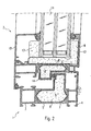
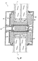
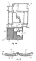
- FIG. 1 shows the use of an evacuated insert in a window frame 1 and a sash 2.
- the frame profile of the sash 1 is in several parts trained and is provided as usual for attachment in the window reveal.
- the Frame profile consists of an inside metal in particular Aluminum profile 3, an outside metal, in particular aluminum profile 4, and a plastic profile connecting them and rolled into edge sections 5.
- the interior of the plastic profile contains an insert 6 consisting of a baggy film 7, which is vacuum-tight and a filling 8, made of non-degassing elements such as e.g. Silica parts that are together can abut and have significant gaps.
- the Gaps are evacuated, so that the film 7 conforms to the filling 8.
- the insert 6 is inserted as mentioned in the cavity of the plastic profile 5, for example, inserted from one end. This will be a significant Thermal bridge break achieved, with the adjacent elements -
- the filling 8 a stiffening of the quasi indirectly evacuated cavity such form that the walls of the cavity so the walls of the plastic profile 5 itself do not deform towards the evacuated interior.
- the sash 2 is in this respect very similar structure.
- a plastic profile 14 is provided in the same way as the window frame in its cavity an insert 6 ' comprising, consisting of a foil bag 7 'and a filling 8'.
- the window thus formed does not have to be arranged vertically but can also be inclined or be arranged horizontally, like a skylight.
- Figure 2 shows a modification of the application of Figure 1 in that the frame profile of the window frame 1 made in one piece from a plastic material is.
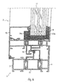
- Figure 3 shows the basic application in a facade construction.
- This consists of a building side, for example, on a pillar or the like fastened inside profile 27, formed here by insulating glazing 28 Panels and an outside profile 29, the edge on the outside the insulating glazing 28 comes to rest and this against the inside profile 27th presses by means of a connecting element 30, which consists of an outside bolt 31, a columnar plastic element 32 and a screw 33, by means of the pillar element 32 is fixed on the inside profile 27.
- the outside Bolt 31 the outer profile 29 by passing, screwed into the column 32 and thus allows the firm connection.
- the interruption of the thermal bridge takes place at least in addition by deposits 34 and 35, which are similar to the deposits 6 and 6 'formed are.
- the insert 35 may be in the plane of two or more parts be educated.
- the bag-like deposits can be from the top or from be aligned in a row in several parts adjacent to each other.
- FIG. 4 shows an application based on FIGS. 1 and 2, which substantially corresponds to that according to FIG. 3, wherein on the one hand evacuated deposits 23a and 23b are provided, and on the other hand evacuated sealed cavities in plastic profiles 15 and 16.
- Figure 5 shows an application based on Figure 3.
- An outer plastic piece 36 and an inner plastic piece 37 which with the inner profile 27 connected (for example screwed into this) are about a metal compound connected, optionally also via a plastic compound 38 in the manner of a screw connection.
- the outer profile 29 is with the outer plastic piece 36 connected by a bolt 31 '.
- the inner plastic piece 37 may be screwed directly into the profile 27 or there by means of Compound 38 can be spread.
- the inside and outside inserts correspond the basic idea, but are only shaped differently and therefore with 34 'and 35', 35 "respectively.
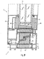
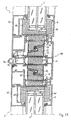
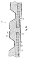
- FIG. 6 shows an exemplary embodiment according to the invention based on the applications according to FIGS. 1, 2 and / or 3
- the plastic profile 5 is formed so that several spaces formed sinc for receiving a respective insert 43 or 44.
- the facing each other Surfaces 45 and 46 of the plastic profiles 5 and 14 formed so that even at a pivoting movement of the sash 2 relative to the window frame 1 a smaller Distance can be achieved. This is done by one over the rest Surfaces of window sash 2 and window frame 1 reaches oblique course, wherein expedient still a step 46 is provided.
- the embedding of the Insulating glazing 11 in this embodiment by three also according to the invention formed deposits 48, 49 and 50 are formed, in which case the insert 50 according to the invention wedge-shaped is formed so that any resulting condensation can run off.
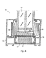
- Fig. 8 shows an embodiment of the invention in a fixed glazing 54, wherein the Frame of fixed glazing from an inside profile 55 made of metal in particular Aluminum and an outside profile 56 made of metal, in particular aluminum as well as an inserted insulating glazing 11 shows.
- the two profiles 55 and 56 are connected by a plastic profile 14 with each other wherein the plastic profile a Has cavity in which, similar to Fig. 7, a liner 51 used is.
- the insulating glazing 11 is similar to Fig. 6 and Fig. 7 in deposits 48, 49 and 50 embedded. Again, the insert 50 is wedge-shaped, so that at the Sloping surface may possibly run off condensation.
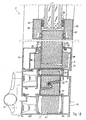
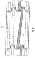
- FIG. 9 shows a corresponding multi-leaf arrangement 57 of a Fixed glazing with a so-called T-rung 58, a generally vertical, if necessary also horizontally or obliquely extending rung, consisting of an internal Profile 59 made of metal, in particular aluminum, an external profile 60 Metal, in particular aluminum and a plastic profile 14 connecting these with an insert 51.
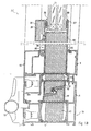
- Fig. 10 shows the application of the embodiment of FIG. 9 in a so-called Gimbal arrangement with a first sash 2 and a second sash 2 'as well as a rung or web element 61, on one of the casements, here the window sash 2 ', namely its profile 10', by means of connecting elements 68, such as a set of screws, is firmly attached.
- connecting elements 68 such as a set of screws
- the web element 61 consists of an inner Profile 62 made of metal, in particular aluminum, an external profile 63 made of metal, in particular aluminum, and connecting these profiles 62 and 63 Plastic profile 64 with spaces for holding Inserts 65, 66 and 67 based on the embodiment of FIG. 7.
- Fig. 11 shows, based on the embodiments of FIGS. 7 and 10 a Herzoglige Arrangement in which a rung or web element 69 fixed vertically, possibly also horizontally, in a window frame (not shown) is arranged.
- the web element 69 consists of an inner profile 70 made of metal, in particular aluminum, an outer profile 71 made of metal, in particular aluminum and a this Profiles 70 and 71 connecting plastic profile 72, the cavities for receiving Inserts 73, 74, 75 has.
- One of the casements, here the Window sash 2 is pivotable via a hinge 76 relative to the web element 69 while the other wing 2 'with respect to another, not shown web element or the window frame, also not shown is pivotable.
- FIGS. 10 and 11 can be suitable for passive houses be called because namely a. k-value. from below 0.8, reachable is what converted equivalent to a fuel oil consumption value of less than 1.5 l / m. This means, that such a house can be built without radiators.
- Fig. 12 shows the application of the invention in an entrance door consisting of a Door leaf 77, a door frame 78 and these hinges connecting 79th
- the entrance door 12 is based on the window arrangement of FIG. 7 and Fig. 1 is formed so that as far as possible repeats the reference numerals used there are, at least as far as the same effect is achieved.
- Deviating is in the deposits 48 to 50 not the insulating glazing 11 embedded, but a frame-like Filling 18, as a panel, consisting of two plates 81 and 82 and in between Insert 83 is formed.
- the plates 81, 82 can made of metal, such as aluminum, or made of plastic or wood.
- the Opening of the frame-like filling 80 is the insulating glazing in a conventional manner 11 used.
- one circumferential cover 84 and 85 provided, which is attached to the filling 80, For example, and as shown are clipped, wherein the cover frame 84, 85 the Insulating glazing 11 surrounded and hold over sealant 86, as known per se is. As shown, the covers 84 and 85 also with inserts 87 and 88 filled.
- Fig. 13 shows a comparison with FIG. 12 modified embodiment in which the filling 80 is not embedded in deposits but abuts the plastic profile 14. This is sufficient if the thermal insulation due to the filling 80 sufficient is.
- the insulating glazing 11 is not surrounded on both sides by covers but only on one side by a cover 84 with insert 88 and seal 86.
- the plate 82 is the filling 80 with a projection 87 formed such that this supernatant covers the insulating glazing 11.
- another sealing means 88 is also provided, the insulating glazing 11 can also be adhered to the supernatant 87.
- Fig. 14 shows the application to a garage door 89.
- Its door leaf 90 is as a panel formed with two plates 91 and 92, between which deposits 93 are provided.
- a reinforcing profile 94 is provided on the edge side.
- the Plates 91, 92 and the profile 94 are preferably made of metal, such as aluminum, however, they can be made of other materials.
- a door frame 95, made of a Profile 96 with insert 97 is anchored in masonry 98.
- the profile 96 can carry fitting elements 99.
- On the door panel 90 is a Fixed frame member 100 which is formed as a profile and an insert 101st may include, which surrounds the door frame 95 and the also fitting elements 102 carries.
- the fitting elements 99 and 102 are prior art and For example, conventional garage door operators, garage door fittings and the like. be grown.
- the profile 103 of the frame member 100 and the profile 96 of the door frame 95 can as shown schematically have thermal separations 104 to thermal bridges between inside and outside to avoid.
- Fig. 15 shows the application to a shutter box 105.
- the shutter box 105 at least on the masonry facing pages covered with panels 106, the a profile 107 with an insert 108 respectively and consist differ only by their dimensions. This can be the extreme Heat loss in the region of the roller shutter boxes 105 are largely avoided without the dimensions of the occupied with the panels 106 shutter box 105 essential to increase.
- Window frame 1 and sash 2 are indicated only schematically and expediently also according to the invention, formed approximately in accordance with FIG. 7.
- Fig. 16 shows the application to a shutter guide 109.
- This consists of a Plastic profile 110 with inserts 111 and 112.
- the profile 110 also has a guide 113 for the shutter or its elements and a Arrangement 114, by means of the profile 110 and thus the shutter guide 109 on Window frame 1 can be attached.
- the window frame 1 and the window sash 2 are also shown only schematically. Of course, such is one Roller shutter guidance also possible with doors and gates:
- roller shutter element 115 has essentially the external appearance a conventional roller shutter element, namely it consists of a profile 116. However, this is filled with deposits 117.
- the profile 116 has hook elements 118 and receptacles 119, in the hook elements 118 of a adjacent profile 115 can intervene.
- the profile 116 can inside a web 120 or the like. Have connecting posts. With lowered shutter hanging an additional heat insulation of the window or the door is achieved. This is especially for passive houses an advantage.
- Roller shutter elements 115 designed according to the invention can also be used in so-called roll-up doors, which are constructed of such elements, and the like can be used.
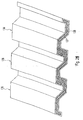
- Fig. 18 shows the application to a sandwich element 121 as it is in particular used in industrial construction.
- the sandwich element 121 consists of a lower substantially flat shell 122 made of aluminum or steel sheet and a profiled upper shell 123, also made of aluminum or steel sheet.
- a foaming 124 of polyurethane or the like Provided.
- panels 125 are embedded, which consist of a profile 126 with insert 127 is.
- the foaming 124 are already provided with cavities in the production, in these then the panels 125 are used.
- an arrangement may consist of the shells 122, 123 and the panels 125 to form the foaming 124 in one Foamed tool.
- the thermal conductivity is greatly reduced.
- the amount of polluting polyurethane foam can be substantial be reduced.
- Figs. 19 and 20 show the application to bricks and out Masons made masonry.
- the brick 128 of FIG. 19 is formed in a conventional manner with longitudinal webs 129, 130 crossbars and perforations 131.
- This brick 128 can be out of all conventional materials such as clay, foam concrete, aerated concrete or the like. Made be. At least certain holes are with Panels 132 provided from a profile 133 with an insert 134th consist.
- the brick 135 of FIG. 20 differs from the brick 128 according to 19 essentially only by the position and design of the cavity or the perforation in which the panel 132 is received.
- the one or more panels 132 can in the corresponding holes 131 already in the. Manufacture of the brick 128 and 129 are used, they can also on site be used in the manufacture of masonry. Since the panels 132 the Effectively affect heat insulation, the webs 129, 130 and the perforations 131 are determined essentially on the basis of statistical considerations. It can also be used in addition metal or Kunststoffarmtechniken to the Reinforcing brick in the thinnest area (not shown). This will be the subsequent application of Styrofoam, especially in cellar areas, superfluous or at least. greatly reduced.
- Fig. 21 shows the application to roof tiles 136. While conventional Roof tiles made of solid material is the roof tile 136 bivalves shaped like a profile and contains in its interior Panel 137 with an insert 138. As with the bricks can be used during the production of the panel 137, but also only be introduced on-site.
- Fis. Fig. 22 shows the application in a loft conversion in which a drying plate 139 like a plasterboard, a wood or a spahnplatte on rafters 140 is fixed and the area between the dry plate 139, the rafters 140 and the outer roof, not shown here, provided with a thermal insulation becomes.
- the thermal insulation consists of a panel 141 consisting of a profile 142 and an insert 143.
- the roof skin side is a trough-shaped trained cover 144 is provided, which consists for example of Styrofoam and essentially serves to unintentional damage of the panel 141 starting to avoid openings in the roof skin.
- the trough 144 is at the Drying plate 139 is attached and the panel 141 in the between trough 144 and Drying plate 139 formed cavity inserted.
- This will be a very high Thermal insulation of the roof truss area achieved without an elaborate thickness Isolation is required. This is particularly advantageous for passive houses.
- Fig. 23 shows the general applicability wherever between two flat, in particular plate or shell-shaped construction elements 142nd and 143 of metal or other material good thermal insulation can be achieved should. Between these two construction elements 142, 143 At least one panel 144 is inserted, which consists of a profile 145 with an insert 146 consists.
- the profile 145 has sufficient inherent rigidity, then it can also be used as a covering of a structural element 142 or 143, it is then attach only to this construction element 142 or 143 as stick.
- Typical application examples for this are hot water tanks for passive or zero energy houses, where the previously usual up to 1 to 2m thick Styrofoam coating can be avoided.
- Other applications include earth and aircraft.
- the weight between the outer skin and inner skin of essential importance For motor vehicles, the entire passenger compartment is particular in the roof area, in the floor area, in the door area and in the rear area but also at the partition to the engine by means of panels according to the invention can be isolated. Again, the low weight of importance.
- the relative high temperatures in the Engine room and also by solar radiation can inside the passenger compartment be greatly reduced.
- the general application is also in everyday things Use possible, for example, in cooking pot side walls and pot lids.
- the heating plate (bottom plate) of the pot not according to this Approach trained.
- the heat is therefore very strong inside the pot retained, which reduces the cooking time while touching the pot and the lid without problems is possible.
- coolers and coolers can be formed in this way. While traditional styrofoam insulated coolers and cool boxes but relatively quickly to a temperature balance between the interior and surroundings come, the heat transfer when using greatly reduced in accordance with the invention equipped panels. In addition, the advantage is the low Height.
- the pipeline based on Fig. 23 may be formed as a double-walled line, wherein between the inner wall and the outer wall evacuated deposits are arranged to the To effect thermal insulation in the sense of interrupting the heat conduction.
Landscapes
- Engineering & Computer Science (AREA)
- Civil Engineering (AREA)
- Structural Engineering (AREA)
- Physics & Mathematics (AREA)
- Thermal Sciences (AREA)
- Wing Frames And Configurations (AREA)
- Building Environments (AREA)
- Insulated Conductors (AREA)
- Bridges Or Land Bridges (AREA)
- Fuel Cell (AREA)
- Thermal Insulation (AREA)
- Seal Device For Vehicle (AREA)
Claims (13)
- Agencement de profilés pour l'interruption d'un pont thermoconducteur entre un côté extérieur et un côté intérieur, avec un élément de construction présentant une insertion, qui forme l'interruption, l'insertion étant une insertion (50, 50') mise sous vide et se composant de sacs de feuilles (7, 7') mis sous vide, fermés de façon étanche au vide, préformés ou pouvant être formés, avec une charge (8, 8') ne dégageant pas de gaz à base de parties qui sont contiguës et laissent des interstices, caractérisé en ce que l'insertion (50, 50') mise sous vide est conçue en forme de clavette, de sorte que de l'eau de condensation éventuellement en formation peut s'écouler.
- Agencement de profilés selon la revendication 1, caractérisé en ce que l'élément de construction est une partie de profilé en matière synthétique présentant une cavité intérieure, qui est insérée entre des parties de profilés en métal (3, 4, 9, 10, 27, 29) de l'agencement de profilés, en particulier des parties de profilé en aluminium.
- Agencement de profilés selon la revendication 1, caractérisé en ce que l'élément de construction est formé par des parties de profilé en matière synthétique (39, 40) qui sont insérées entre des parties de profilé en métal (3, 4, 9, 10) de l'agencement de profilé, en particulier des parties de profilé en aluminium et qui délimitent avec ceux-ci une cavité intérieure (41, 42).
- Agencement de profilés selon la revendication 3, caractérisé en ce que les parties de profilé en matière synthétique (41, 42) sont insérées de façon étanche au vide dans les parties de profilé en métal (3, 4, 9, 10).
- Agencement de profilés selon la revendication 1, caractérisé en ce que l'interruption est prévue dans une partie de liaison d'une partie de profilé en matière synthétique.
- Agencement de profilés selon la revendication 1, caractérisé en ce que l'interruption d'une première partie (34, 34' ) côté extérieur et une seconde partie (35, 35', 35'') côté intérieur ou côté bâtiment, qui peuvent recevoir entre elles conjointement avec des parties de profilé (29, 27) appropriées de l'agencement de profilé des panneaux, des agencements de vitres (28) ou des charges (80), les parties de profilé (27, 29) et les parties (34, 35, 34', 35', 35'') présentant des éléments de liaison (30, 30') traversant comme parties (32, 36, 37) interrompant la conduction de chaleur.
- Agencement de profilés selon l'une quelconque des revendications 1 à 6, caractérisé en ce que l'insertion (6, 6', 34, 35, 34', 35', 35'') est conçue en plusieurs parties.
- Agencement de profilés selon l'une quelconque des revendications 1 à 7, caractérisé en ce que les parois des profilés de l'agencement de profilés sont dimensionnées ou soutenues réciproquement et dimensionnées de telle sorte qu'elles ne se déforment pas lors de l'évacuation de l'air.
- Agencement de profilés selon l'une quelconque des revendications 1 à 8, caractérisé en ce que le côté intérieur peut être attribué à une conduite de transport et, dans l'état attribué, l'interruption interrompt la conduction de chaleur entre l'article transporté et l'environnement extérieur ou inversement.
- Agencement de profilés selon l'une quelconque des revendications 1 à 8, caractérisé en ce que le côté intérieur peut être attribué à un espace ou à un récipient et, dans l'état attribué, l'interruption interrompt la conduction thermique entre l'intérieur de l'espace ou du récipient et l'environnement extérieur ou inversement.
- Agencement de profilés selon la revendication 10, caractérisé en ce que l'espace est prévu dans un véhicule, près d'un véhicule ou sur un véhicule, en particulier un véhicule aéronef.
- Agencement de profilés selon l'une quelconque des revendications précédentes, caractérisé en ce qu'il est fabriqué complètement à base d'un matériau synthétique.
- Utilisation de l'agencement de profilés selon l'une quelconque des revendications précédentes pour la liaison entre des profilés côté intérieur et des profilés côté extérieur de cadres de fenêtre ou de porte, de vantaux de fenêtre ou de porte, de barreaux de fenêtre, entre le côté intérieur et le côté extérieur de portails, de caissons de volet roulant, de guides de volet roulant, d'éléments de volet roulant, d'éléments sandwich dans la construction industrielle, de briques, de tuiles de toit, de revêtements, de plafonds de sauvetage et similaires.
Applications Claiming Priority (5)
| Application Number | Priority Date | Filing Date | Title |
|---|---|---|---|
| DE19923560 | 1999-05-21 | ||
| DE19923560 | 1999-05-21 | ||
| DE19947601A DE19947601A1 (de) | 1999-05-21 | 1999-10-04 | Profilanordnung für Rahmen oder Flügel von Fenstern oder Türen oder Fassadenanordnungen oder dergleichen Anordnungen |
| DE19947601 | 1999-10-04 | ||
| PCT/EP2000/004477 WO2000071849A1 (fr) | 1999-05-21 | 2000-05-17 | Agencement de profiles pour l'interruption d'un pont thermoconducteur entre un cote interieur et un cote exterieur |
Publications (2)
| Publication Number | Publication Date |
|---|---|
| EP1179112A1 EP1179112A1 (fr) | 2002-02-13 |
| EP1179112B1 true EP1179112B1 (fr) | 2005-02-02 |
Family
ID=26053479
Family Applications (1)
| Application Number | Title | Priority Date | Filing Date |
|---|---|---|---|
| EP00936751A Expired - Lifetime EP1179112B1 (fr) | 1999-05-21 | 2000-05-17 | Agencement de profiles pour l'interruption d'un pont thermoconducteur entre un cote interieur et un cote exterieur |
Country Status (5)
| Country | Link |
|---|---|
| EP (1) | EP1179112B1 (fr) |
| AT (1) | ATE288531T1 (fr) |
| AU (1) | AU5213800A (fr) |
| CA (1) | CA2374575A1 (fr) |
| WO (1) | WO2000071849A1 (fr) |
Cited By (1)
| Publication number | Priority date | Publication date | Assignee | Title |
|---|---|---|---|---|
| DE202012002498U1 (de) | 2011-06-03 | 2012-04-26 | Teuvo Vaittinen | Tür, Metallkonstruktionsprofil einer Zarge oder eines Rahmens für eine Tür oder ein Fenster |
Families Citing this family (18)
| Publication number | Priority date | Publication date | Assignee | Title |
|---|---|---|---|---|
| DE10101689A1 (de) | 2001-01-15 | 2003-11-13 | Woschko Gabriele | Fenster, Mauerstein, Wand- und Deckenverkleidung mit Vakuumdämmeinlage |
| DE102005043847A1 (de) * | 2005-09-13 | 2007-03-22 | Niveau Fenster Westerburg Gmbh | Fensterrahmen mit Wärmedämmung, Fenster und Verfahren zur Montage |
| GB2434395B (en) * | 2006-08-08 | 2011-03-09 | Bowater Building Products Ltd | A frame member for a window frame and a window frame comprising such a frame member |
| DE102006061655A1 (de) * | 2006-10-13 | 2008-04-17 | Raico Bautechnik Gmbh | Wärmedämmleiste |
| DE102006058804A1 (de) | 2006-12-13 | 2008-06-19 | Woschko Winlite Gmbh | Verfahren zur Herstellung eines Vakuumpaneels, derartiges Vakuumpaneel sowie ein dieses verwendender Mauerstein |
| EP2088276B1 (fr) | 2008-02-09 | 2017-05-24 | HUECK GmbH & Co. KG | Agencement de profilé isolant entre dormant et cadre d'une fenêtre ou porte |
| ITFE20080022A1 (it) * | 2008-07-17 | 2010-01-18 | Francesca Cavedagna | Profilo tubolare avente le camere interne chiuse ermeticamente e sotto vuoto |
| BE1018344A3 (nl) * | 2008-11-21 | 2010-09-07 | Reynaers Aluminium Nv | Verbeterd samengesteld profiel voor het kader van een raam of deur. |
| IE86524B1 (en) * | 2009-07-15 | 2015-04-08 | Architectural & Metal Systems Ltd | Insulated frame member |
| EP2628882A1 (fr) * | 2012-02-14 | 2013-08-21 | Alcoa Aluminium Deutschland, Inc. | Agencement châssis-vantail comprenant au moins un élément d'isolation à pliage central |
| US9441415B2 (en) * | 2012-12-27 | 2016-09-13 | Guardian Industries Corp. | Window having vacuum insulated glass (VIG) unit and frame including vacuum insulated structure(s) |
| BE1021374B1 (fr) * | 2013-05-28 | 2015-11-10 | Sa Pierret Systems | Profile super-isolant |
| US9447627B2 (en) | 2014-05-27 | 2016-09-20 | Guardian Industries Corp. | Window frame system for vacuum insulated glass unit |
| US9845635B2 (en) | 2014-05-27 | 2017-12-19 | Guardian Glass, Llc. | Window frame system for vacuum insulated glass unit |
| KR102000789B1 (ko) * | 2018-05-24 | 2019-07-16 | 주식회사 필로브 | 세그먼트 타입의 윈도우 프레임을 포함한 슬라이딩 창호 시스템을 구성하는 고정창의 유리 고정 가스켓과 창유리 패널 고정 브라켓의 설치 구조 |
| DE102018007394B4 (de) * | 2018-09-19 | 2020-06-10 | Fkn Fassaden Gmbh & Co. Kg | Modulares Fassadensystem zum Aufbau von extrem wärmegedämmten Gebäudewänden und Verfahren zur Herstellung dieses Fassadensystems |
| CN111594703A (zh) * | 2019-02-21 | 2020-08-28 | 北京航天试验技术研究所 | 一种具有外置补偿板的真空绝热管小真空焊接连接结构 |
| CN115749529B (zh) * | 2022-12-05 | 2025-08-19 | 南通大通装饰工程有限公司 | 一种系统门窗用隔热冷桥多腔体铝合金型材 |
Citations (7)
| Publication number | Priority date | Publication date | Assignee | Title |
|---|---|---|---|---|
| EP0106103A1 (fr) * | 1982-10-13 | 1984-04-25 | ERNO Raumfahrttechnik Gesellschaft mit beschränkter Haftung | Procédé de fabrication d'éléments sous vide pour l'isolation thermique |
| US4529638A (en) * | 1980-12-09 | 1985-07-16 | Matsushita Electric Industrial Co., Ltd. | Thermal insulator |
| US4636415A (en) * | 1985-02-08 | 1987-01-13 | General Electric Company | Precipitated silica insulation |
| US4668551A (en) * | 1984-11-13 | 1987-05-26 | Nippon Sanso Kabushiki Kaisha | Evacuated heat insulation unit and method of manufacturing same |
| DE3634325A1 (de) * | 1986-10-08 | 1988-04-21 | Steinmueller Gmbh L & C | Druckbehaelter, mit einem mit hilfe von spannelementen vorgespannten behaeltergrundkoerper |
| EP0355294A2 (fr) * | 1988-08-24 | 1990-02-28 | Degussa Aktiengesellschaft | Corps façonné pour l'isolation thermique |
| EP0619452A1 (fr) * | 1993-04-07 | 1994-10-12 | Bosch-Siemens HausgerÀ¤te GmbH | Appareil comportant des parois isolées avec poudre sous vide |
Family Cites Families (6)
| Publication number | Priority date | Publication date | Assignee | Title |
|---|---|---|---|---|
| ATE1027T1 (de) * | 1979-03-23 | 1982-05-15 | Lothar Schilf | Verfahren zur herstellung von elementen zur innenliegenden waermeisolation von hochdruckbehaeltern oder roehren, und ein nach diesem verfahren hergestelltes rohr. |
| DE4203760C2 (de) * | 1992-02-10 | 1995-08-24 | Wilfried Ensinger | Verbundprofil |
| DE4212587A1 (de) * | 1992-04-15 | 1993-10-21 | Wicona Bausysteme | Wärmegedämmtes Verglasungssystem o. dgl. |
| DE4342946A1 (de) * | 1993-12-16 | 1995-06-22 | Licentia Gmbh | Wärmeisolierelement mit einem evakuierten Hohlraum |
| DE19519984A1 (de) * | 1995-05-24 | 1996-11-28 | Ulrich Kasperek | AHUK-Isolierschichten |
| DE19537459C1 (de) * | 1995-10-07 | 1997-04-10 | Edgar Hoffmann | Fenster aus Profilteilen mit Hohlkammern |
-
2000
- 2000-05-17 AT AT00936751T patent/ATE288531T1/de not_active IP Right Cessation
- 2000-05-17 AU AU52138/00A patent/AU5213800A/en not_active Abandoned
- 2000-05-17 EP EP00936751A patent/EP1179112B1/fr not_active Expired - Lifetime
- 2000-05-17 CA CA002374575A patent/CA2374575A1/fr not_active Abandoned
- 2000-05-17 WO PCT/EP2000/004477 patent/WO2000071849A1/fr not_active Ceased
Patent Citations (7)
| Publication number | Priority date | Publication date | Assignee | Title |
|---|---|---|---|---|
| US4529638A (en) * | 1980-12-09 | 1985-07-16 | Matsushita Electric Industrial Co., Ltd. | Thermal insulator |
| EP0106103A1 (fr) * | 1982-10-13 | 1984-04-25 | ERNO Raumfahrttechnik Gesellschaft mit beschränkter Haftung | Procédé de fabrication d'éléments sous vide pour l'isolation thermique |
| US4668551A (en) * | 1984-11-13 | 1987-05-26 | Nippon Sanso Kabushiki Kaisha | Evacuated heat insulation unit and method of manufacturing same |
| US4636415A (en) * | 1985-02-08 | 1987-01-13 | General Electric Company | Precipitated silica insulation |
| DE3634325A1 (de) * | 1986-10-08 | 1988-04-21 | Steinmueller Gmbh L & C | Druckbehaelter, mit einem mit hilfe von spannelementen vorgespannten behaeltergrundkoerper |
| EP0355294A2 (fr) * | 1988-08-24 | 1990-02-28 | Degussa Aktiengesellschaft | Corps façonné pour l'isolation thermique |
| EP0619452A1 (fr) * | 1993-04-07 | 1994-10-12 | Bosch-Siemens HausgerÀ¤te GmbH | Appareil comportant des parois isolées avec poudre sous vide |
Cited By (1)
| Publication number | Priority date | Publication date | Assignee | Title |
|---|---|---|---|---|
| DE202012002498U1 (de) | 2011-06-03 | 2012-04-26 | Teuvo Vaittinen | Tür, Metallkonstruktionsprofil einer Zarge oder eines Rahmens für eine Tür oder ein Fenster |
Also Published As
| Publication number | Publication date |
|---|---|
| CA2374575A1 (fr) | 2000-11-30 |
| AU5213800A (en) | 2000-12-12 |
| WO2000071849A1 (fr) | 2000-11-30 |
| EP1179112A1 (fr) | 2002-02-13 |
| ATE288531T1 (de) | 2005-02-15 |
Similar Documents
| Publication | Publication Date | Title |
|---|---|---|
| EP1179112B1 (fr) | Agencement de profiles pour l'interruption d'un pont thermoconducteur entre un cote interieur et un cote exterieur | |
| GB2067230A (en) | Profile bar | |
| EP2642060B1 (fr) | Battant de fenêtre ou de porte | |
| DE102007058931A1 (de) | Glasfassaden | |
| EP0005499A1 (fr) | Fenêtre comportant un collecteur d'énergie solaire | |
| EP2733293B1 (fr) | Système de cadre de montage | |
| WO2011012295A2 (fr) | Fenêtre ouvrant vers l'extérieur | |
| EP2466049B1 (fr) | Composant de fenêtre | |
| EP4305266A1 (fr) | Construction de façade | |
| EP1205625A2 (fr) | Porte, fenêtre ainsi que dispositif de verrouillage avec isolation thermique améliorée | |
| DE19704112C2 (de) | Wärmedämmende Fassadenverkleidung | |
| WO2019063326A1 (fr) | Système de vitrage de sécurité, en particulier système de vitrage isolant de sécurité, et vitrage de sécurité, en particulier vitrage isolant de sécurité | |
| DE102007054369B4 (de) | Zarge für den Einbau eines Fensters oder einer Tür | |
| DE19847110C2 (de) | Bauelement zum Erstellen von tragenden Wänden, Decken, Böden oder Dächern | |
| AT522638B1 (de) | Profil | |
| DE29811818U1 (de) | Mehrschichtiger Wandaufbau mit Kasten für Jalousien oder Rolladen | |
| DE19709938A1 (de) | Fensteranordnung | |
| DE102009020003A1 (de) | Glasfassaden | |
| AT405862B (de) | Kastenfenster | |
| DE19806886A1 (de) | Mehrschichtige Außenwand insbesondere für vorgefertigte Niedrigenergiehäuser | |
| AT1730U1 (de) | Wandkonstruktion für und bauwerke in ständerbauweise | |
| CH691696A5 (de) | Fenster. | |
| AT17876U1 (de) | Dämmendes verdunkelndes System zur Reduzierung der Wärmeverluste in einer Öffnung einer Gebäudewand | |
| DE19736860A1 (de) | Wärmegedämmte Fassade mit Fensterbändern | |
| DE2203871A1 (de) | Geschosshohe aussenwandplatte |
Legal Events
| Date | Code | Title | Description |
|---|---|---|---|
| PUAI | Public reference made under article 153(3) epc to a published international application that has entered the european phase |
Free format text: ORIGINAL CODE: 0009012 |
|
| 17P | Request for examination filed |
Effective date: 20011121 |
|
| AK | Designated contracting states |
Kind code of ref document: A1 Designated state(s): AT BE CH CY DE DK ES FI FR GB GR IE IT LI LU MC NL PT SE |
|
| AX | Request for extension of the european patent |
Free format text: AL;LT;LV;MK;RO;SI |
|
| 17Q | First examination report despatched |
Effective date: 20020621 |
|
| RBV | Designated contracting states (corrected) |
Designated state(s): AT CH DE LI |
|
| GRAP | Despatch of communication of intention to grant a patent |
Free format text: ORIGINAL CODE: EPIDOSNIGR1 |
|
| GRAS | Grant fee paid |
Free format text: ORIGINAL CODE: EPIDOSNIGR3 |
|
| GRAA | (expected) grant |
Free format text: ORIGINAL CODE: 0009210 |
|
| AK | Designated contracting states |
Kind code of ref document: B1 Designated state(s): AT CH DE LI |
|
| REG | Reference to a national code |
Ref country code: CH Ref legal event code: EP |
|
| REG | Reference to a national code |
Ref country code: IE Ref legal event code: FG4D Free format text: GERMAN |
|
| REF | Corresponds to: |
Ref document number: 50009426 Country of ref document: DE Date of ref document: 20050310 Kind code of ref document: P |
|
| PG25 | Lapsed in a contracting state [announced via postgrant information from national office to epo] |
Ref country code: AT Free format text: LAPSE BECAUSE OF NON-PAYMENT OF DUE FEES Effective date: 20050517 |
|
| PG25 | Lapsed in a contracting state [announced via postgrant information from national office to epo] |
Ref country code: CH Free format text: LAPSE BECAUSE OF NON-PAYMENT OF DUE FEES Effective date: 20050531 Ref country code: LI Free format text: LAPSE BECAUSE OF NON-PAYMENT OF DUE FEES Effective date: 20050531 |
|
| PLBE | No opposition filed within time limit |
Free format text: ORIGINAL CODE: 0009261 |
|
| STAA | Information on the status of an ep patent application or granted ep patent |
Free format text: STATUS: NO OPPOSITION FILED WITHIN TIME LIMIT |
|
| REG | Reference to a national code |
Ref country code: CH Ref legal event code: PL |
|
| 26N | No opposition filed |
Effective date: 20051103 |
|
| PGFP | Annual fee paid to national office [announced via postgrant information from national office to epo] |
Ref country code: DE Payment date: 20100730 Year of fee payment: 11 |
|
| REG | Reference to a national code |
Ref country code: DE Ref legal event code: R119 Ref document number: 50009426 Country of ref document: DE |
|
| REG | Reference to a national code |
Ref country code: DE Ref legal event code: R119 Ref document number: 50009426 Country of ref document: DE |
|
| PG25 | Lapsed in a contracting state [announced via postgrant information from national office to epo] |
Ref country code: DE Free format text: LAPSE BECAUSE OF NON-PAYMENT OF DUE FEES Effective date: 20111130 |