EP1179231B1 - Synchronisation von rundfunkmitteln durch satellit und/oder mikrowellenverbindung - Google Patents
Synchronisation von rundfunkmitteln durch satellit und/oder mikrowellenverbindung Download PDFInfo
- Publication number
- EP1179231B1 EP1179231B1 EP00939320A EP00939320A EP1179231B1 EP 1179231 B1 EP1179231 B1 EP 1179231B1 EP 00939320 A EP00939320 A EP 00939320A EP 00939320 A EP00939320 A EP 00939320A EP 1179231 B1 EP1179231 B1 EP 1179231B1
- Authority
- EP
- European Patent Office
- Prior art keywords
- transmitters
- frequency
- recited
- tone
- broadcast
- Prior art date
- Legal status (The legal status is an assumption and is not a legal conclusion. Google has not performed a legal analysis and makes no representation as to the accuracy of the status listed.)
- Expired - Lifetime
Links
- 230000005540 biological transmission Effects 0.000 claims abstract description 30
- 230000001360 synchronised effect Effects 0.000 claims description 19
- 238000000034 method Methods 0.000 claims description 10
- 238000004891 communication Methods 0.000 claims description 7
- 230000000694 effects Effects 0.000 abstract description 4
- 239000000969 carrier Substances 0.000 description 6
- 238000010586 diagram Methods 0.000 description 5
- 238000010009 beating Methods 0.000 description 4
- 230000008901 benefit Effects 0.000 description 2
- 238000012986 modification Methods 0.000 description 2
- 230000004048 modification Effects 0.000 description 2
- 230000004075 alteration Effects 0.000 description 1
- 238000003491 array Methods 0.000 description 1
- 230000015572 biosynthetic process Effects 0.000 description 1
- 230000000903 blocking effect Effects 0.000 description 1
- 239000003990 capacitor Substances 0.000 description 1
- 238000006243 chemical reaction Methods 0.000 description 1
- 230000002939 deleterious effect Effects 0.000 description 1
- 238000009795 derivation Methods 0.000 description 1
- 230000003467 diminishing effect Effects 0.000 description 1
- 230000001747 exhibiting effect Effects 0.000 description 1
- 238000001914 filtration Methods 0.000 description 1
- 230000001788 irregular Effects 0.000 description 1
- 238000012545 processing Methods 0.000 description 1
- 230000001105 regulatory effect Effects 0.000 description 1
- 238000000926 separation method Methods 0.000 description 1
- 238000003786 synthesis reaction Methods 0.000 description 1
- 238000013519 translation Methods 0.000 description 1
Images

Classifications
-
- H—ELECTRICITY
- H04—ELECTRIC COMMUNICATION TECHNIQUE
- H04B—TRANSMISSION
- H04B7/00—Radio transmission systems, i.e. using radiation field
- H04B7/14—Relay systems
- H04B7/15—Active relay systems
- H04B7/185—Space-based or airborne stations; Stations for satellite systems
- H04B7/18523—Satellite systems for providing broadcast service to terrestrial stations, i.e. broadcast satellite service
Definitions
- Broadcast communications have become an important and rapidly growing industry. During the past few years, many new frequencies and channels have been allocated to provide an increased variety of programming. Many new broadcast stations have also been recently established to improve broadcast coverage to more remote receiver locations. However, coverage has not yet become complete in the United States, in large part due to mountain ranges and the fact that FM radio and television frequencies are not reflected from upper layers of the atmosphere and thus require substantially a line-of-sight transmission path for reliable communications to be carried out. Even in urban areas, some locations will be able to achieve only marginal reception due to reflections from buildings, aircraft and the like causing so-called multi-path distortion and signal cancellation.
- the transmission pattern of broadcast transmitters may require modification with specially designed antenna arrays.
- broadcast transmitters using the same channel or frequency are not permitted within one hundred seventy miles of each other and transmission power is closely regulated.
- the carrier frequencies of respective transmitters in a triad are offset from each other by 10KHz or 20KHz under present frequency allocation regulations of the Federal Communications commission to facilitate discrimination.
- beating of carriers may seriously degrade reception of either signal.
- a translator is essentially a strategically located slave transmitter which receives a broadcast signal on one or more frequencies or channels and provides retransmission on other frequencies or channels.
- the term translator derives from the function of translating the modulation of a received signal to a different carrier signal.
- the translators which may be used are also subject to regulations as to minimum geographical separation, transmission pattern and frequency offset as broadcast stations. As an additional complicating factor, frequency allocation regulations allow deviation of carrier frequency of broadcast transmitters 50Hz above or below a nominal carrier frequency.
- the frequency allocation arrangement currently in use while based on sound technical requirements, tends to diminish signal quality and limit the number of channels which can be used in any given geographical area. This, in turn, limits the amount of information which can be concurrently communicated at a time when frequency allocations are at a premium and demand for access to information and programming variety are rapidly increasing.
- US5038403 relates to a simulcast transmission system which includes time delay circuits in the communication links between primary and secondary transmitting stations.
- the invention provides a method of synchronizing a plurality of broadcast transmitters, including steps of relying a synchronization tone to said plurality of transmitters, multiplying a frequency of said synchronization tone by rectification of said synchronization tone to obtain a desired synchronous carrier frequency at each of said plurality of transmitters, and modulating said carrier frequency simultaneously at said plurality of broadcast transmitters with a modulation signal.
- the invention further provides a broadcast transmitter system including a plurality of transmitters having a common allocated channel or nominal carrier frequency, each respective transmitter of said plurality of transmitters including means for receiving a tone having a frequency transmitted to each of said plurality of transmitters, means for multiplying said frequency of said tone to derive a carrier frequency synchronous among said plurality of transmitters, said means including a rectifier and means for modulating said carrier frequency with a broadcast signal.
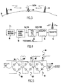
- FIG. 1 a generalized geographical environment of broadcast transmissions as presently conducted and as conducted in accordance with the invention, respectively.
- terrain 10 of the earth's surface is essentially arbitrary and a single obstruction to a line-of-sight transmission path is depicted as a mountain 12 for simplicity.
- the major hardware facilities of the transmission environment of Figures 1 and 2 are not only depicted identically (at the level of abstraction provided by these Figures) for clarity but illustrate that no major alteration thereof is required in order to implement the invention and provide the particular signal paths for particular signals illustrated in Figure 2A and 2B.
- transmitter 14 represents an up-link 26 to satellite 18.
- Transmitter 16 is a broadcast transmitter broadcasting a modulated signal on a given channel (e.g. channel 3) and which can also provide an up-link 28 to satellite 18 and/or broadcast a signal to up-link transmitter 14 for transmission to satellite 18.
- Transmitter 20 represents a translator which receives the broadcast signal from transmitter 16 and rebroadcasts the same signal 38 on a different channel (e.g. channel 56) from the channel on which the signal was received, as depicted at 30.
- a customer may thus receive a broadcast signal 30 (on a translated channel or frequency) from translator 20 through antenna 22 or from direct satellite transmission 32 from satellite 18 through antenna 24 (and decoder, if used).
- a broadcast signal 30 on a translated channel or frequency
- the customer could also receive the broadcast signal 38 from transmitter 16 on the original channel or frequency. Therefore, there are, in this example (as is generally the case at the present time), redundant sources for a broadcast signal and the source providing the qualitatively better or best signal can be chosen by the customer by means of the directionality of antennas 22, 24 or a choice therebetween.
- the broadcast environment illustrated in Figures 1, 2A and 2B is very much simplified to include only a single broadcast signal (although the up-link transmitter 14 and satellite 18 could be handling many more signals for many diverse purposes such as geo-location, telecommunications, and the like).
- numerous transmitters 16 and, possibly, numerous translators 20 will be present.
- several satellites 18 may provide a signal source for a relatively large number of broadcast signals of numerous broadcast channels. Therefore, the present broadcast environment uses a large portion of the satellite bandwidth for respective broadcast signals.
- the geographic locations and potentially overlapping coverage patterns use a large portion of the available frequency or channel allocations to minimize potential interference and to improve coverage with translators 20.
- the invention seeks to synchronize the carrier and modulation of all transmitters broadcasting on a given channel or carrier frequency over an arbitrary geographical area which may vary in extent from current coverage patterns (including the coverage patterns of translators) to world-wide.
- up-link transmitter 14 need only transmit (34) a number of modulation tone signals, as will be discussed below, which are relayed to transmitter 16' and translator/booster 20', as indicated by reference numeral 36.
- broadcast programming could continue to be transmitted and relayed in the manner described above to maintain satellite 18 as a redundant source of such signals.
- the tones received at transmitters 16' and 20' will thus be the same and are necessarily synchronized but for a slight potential phase delay which is unimportant to the principles or practice of the invention. Any drift of the original tone(s) will be exactly the same at all locations and will be synchronized wherever received.
- microwave-link transmitter 14' need only transmit a number of modulation tone signals 34, as will be discussed below, which are relayed to transmitter 16' and translator/booster 20'.
- broadcast programming could continue to be transmitted and relayed in the manner described above to maintain broadcast transmitter 14' and/or satellite 18 as redundant sources of such signals.
- the tones received at transmitters 16' and 20' will thus be the same and are necessarily synchronized but for a slight potential phase delay which is unimportant to the principles or practice of the invention. Any drift of the original tone(s) 40 will be exactly the same at all locations and will be synchronized wherever received as in the case of a satellite link, as described above.
- the basic principle of the invention using either a satellite link or a microwave link for transmission of tones by which a plurality of transmitters are synchonized on a single frequency, is to derive synchronized carrier signals at a plurality of transmitter and/or translator/booster locations from the modulation tones 36 received from satellite 18 and/or from a microwave transmitter 14'.
- Booster 20' can thus receive a modulation signal from transmitter 16' (preferably over a microwave link 42 since the broadcast signal cannot be received on the same channel or frequency on which the booster 20' will transmit) and provide a modulated carrier signal of increased signal strength to customer antenna 22 precisely in synchronism with the modulated carrier signal transmitted by transmitter 16'. Since these signals are synchronized, they cannot interfere with each other. The signal strength is the sum of the signal components from transmitter 16' and booster 20' reaching antenna 22.
- the broadcast environment depicted in Figure 3 represents an early stage of the preferred implementation of the invention for one transmitter but not necessarily other transmitters in a triad and which may or may not continue to utilize current frequency offsets. If the invention was applied to only one of transmitters 50, 52, (as would be the case in an early stage of implementation of the invention) this effect would, potentially, be somewhat enhanced by employing frequency offsets in the current manner although beating of carriers would be possible.
- the invention thus provides for not only full channel or frequency usage for different programming on respective channels (since no channel allocations need be allocated to translators 20) but, in some cases, can provide even more programming diversity beyond the number of available channels.
- the invention be employed worldwide using existing transmitters and translators/boosters, it is seen that the invention can be employed locally and is fully compatible with gradual implementation while providing improved discrimination.
- the transmission from satellite 18 including a fixed frequency tone is received at local receiver 60 and demodulated at 62 to produce the original tone 64 transmitted from up-link transmitter 14.
- the frequency of the tone 64 is then multiplied at 66, preferably by an integral power of two, to produce the desired carrier frequency 68 which is modulated at modulator 70 with a desired programming signal and transmitted at transmitter 74.
- the same signal processing elements shown in Figure 4 are provided in both transmitters 16' and boosters 20'.
- the invention can be practiced using other frequency multiples (e.g. three, five, seven, etc.) multiples of integral powers of two are much preferred provide for minimal hardware cost while having the additional benefit that the original tone signal remains in the carrier signal and thus more reliably locks the carrier frequencies together in synchronism.
- a phase locked loop of other signal synthesis arrangement with frequency control which merely racks the tone signal must be employed.
- the carrier frequencies derived therefrom will remain precisely locked together if an integral power of two multiple is employed while, if other multiples are used, tracking frequency drift may or may not be accomplished and significant variation in phase may be engendered while doing so.
- boosters 20' and transmitter 16' differ principally by the location where the modulating signal 72 is initially provided and, possibly (and largely by convention) transmission power and antenna array define the basic coverage pattern.
- this latter potential distinction is of diminishing importance as the invention is implemented over larger geographic areas with common programming for transmitters operating on a given frequency or channel. That is, as common programming is transmitted synchronously by a plurality of transmitters 16', the function of all transmitters other than the originating transmitter parallels that of boosters 20' which are allocated to avoiding coverage pattern anomalies.
- the frequency of the tone transmitted to and relayed by satellite 18 is chosen in view of the carrier frequency to be derived and is a power of two sub-multiple of the desired carrier frequency.
- the power-of-two sub-multiple can be freely chosen as long as the tone remains within the satellite transmission link bandwidth (currently 25 MHz) or the microwave transmission bandwidth (also currently 25 MHz between 70MHz to 95MHz).
- the carrier frequency for channel 3 is 61.25 MHz. Division of this frequency by 16 (2 5 ) yields a tone frequency of approximately 3.9 MHz which corresponds to the satellite or nicrowave transmission bandwidth.
- the carrier frequency for channel 13 is 211.25 MHz. Division of this frequency by 64 (2 7 ) yields a tone frequency of approximately 4.9 MHz which also corresponds to the satellite or microwave transmission bandwidth. Any desired carrier frequency can thus be generated by appropriate choice of tone and power of two sub-multiple and corresponding power of two multiplier.
- a representative portion of a power of two multiplier is shown corresponding to a frequency multiple of eight and having three frequency doubler stages 80, 82, 84.
- the preferred frequency doubler stage is simply a full-wave rectifier circuit.
- DC blocking capacitors 86 are provided between all frequency doubler stages and tuned amplifiers such as 88 (or schematically indicated as 88') are provided between all stages (e.g. 88') or periodically (e.g. 88) to remove harmonics at the frequency provided by the preceding frequency doubler stage.
- tuned amplifiers perform a filtering function at a particular frequency as well as providing gain to maintain a desired amplitude after recitification.
- the invention provides an inexpensive and easily implemented arrangement for synchronizing plural transmitters operating on any of a large plurality of channels or carrier frequencies.
- the invention is particularly applicable to both amplitude modulated video and digital video as well as other signals which do not employ carrier frequency modulation.
- the need for direct satellite signal reception of programming is much reduced but can be provided compatibly with the invention, as desired. That is, full broadcast coverage may be achieved by booster transmitters (provided, for example, by simple and inexpensive conversion of existing translators) and there is thus no need to rely on satellite relay transmissions to overcome obstacles to line-of-sight transmission paths since there is no trade-off between the number of booster transmitters employed and the number of channels available for independent programming.
- booster transmitters provided, for example, by simple and inexpensive conversion of existing translators
- satellite relay transmissions to overcome obstacles to line-of-sight transmission paths since there is no trade-off between the number of booster transmitters employed and the number of channels available for independent programming.
- more satellite relay capacity can be allocated to other purposes.
Landscapes
- Engineering & Computer Science (AREA)
- Physics & Mathematics (AREA)
- Astronomy & Astrophysics (AREA)
- Aviation & Aerospace Engineering (AREA)
- General Physics & Mathematics (AREA)
- Computer Networks & Wireless Communication (AREA)
- Signal Processing (AREA)
- Radio Relay Systems (AREA)
Claims (19)
- Verfahren zur Synchronisation einer Vielzahl von Rundfunksendern mit den Schritten:Weiterleiten eines Synchronisationstons an die Vielzahl von Sendern,Vervielfachen einer Frequenz des Synchronisationstons durch Gleichrichtung des Synchronisationstons, um eine gewünschte Synchronträgerfrequenz in jedem aus der Vielzahl von Sendern zu gewinnen, undgleichzeitiges Modulieren der Trägerfrequenz in der Vielzahl von Rundfunksendern mit einem Modulationssignal.
- Verfahren nach Anspruch 1 mit dem weiteren Schritt:Ableiten des Modulationssignals in einem aus der Vielzahl von Sendern von einem Signal, das von einem anderen aus der Vielzahl der Sender bereitgestellt wird.
- Verfahren nach Anspruch 2, wobei das Modulationssignal von einem Signal abgeleitet wird, das an den einen aus der Vielzahl von Sendern über eine Richtfunkübertragungsstrecke von dem anderen aus der Vielzahl von Sendern übertragen wird.
- Verfahren nach Anspruch 1, wobei der Vervielfachungsschritt den Schritt aufweist: Vervielfachen des Synchronisationstons um einen Faktor zwei in jeder aus einer Vielzahl von Stufen.
- Verfahren nach Anspruch 1, mit dem weiteren Schritt:Berechnen einer Frequenz des Synchronisationstons durch Teilen einer gewünschten Trägerfrequenz durch eine ganzzahlige Potenz von zwei.
- Verfahren nach Anspruch 1, mit dem weiteren Schritt:Unterscheiden beim Empfang zwischen Signalen von jeweiligen Rundfunksendern mit einem gemeinsamen zugeteilten Kanal oder einer gemeinsamen zugeteilten Frequenz mit einer Richtantenne.
- Verfahren nach Anspruch 1, wobei der Schritt des Weiterleitens eines Synchronisationstons unter Verwendung einer Satellitenübertragungsstrecke durchgeführt wird.
- Verfahren nach Anspruch 1, wobei der Schritt des Weiterleitens eines Synchronisationstons unter Verwendung einer Richtfunkübertragungsstrecke durchgeführt wird.
- Rundfunksendersystem mit
einer Vielzahl von Sendern mit einem gemeinsam zugeteilten Kanal oder einer gemeinsam zugeteilten Soll-Trägerfrequenz, wobei jeder jeweilige Sender aus der Vielzahl von Sendern aufweist:eine Einrichtung zum Empfangen eines Tons mit einer an jeden aus der Vielzahl von Sendern übertragenen Frequenz,eine Einrichtung zum Vervielfachen der Frequenz des Tons, um eine Trägerfrequenz abzuleiten, die zwischen der Vielzahl von Sendern synchron ist, wobei die Einrichtung einen Gleichrichter aufweist, undeine Einrichtung zum Modulieren der Trägerfrequenz mit einem Rundfunksignal. - System nach Anspruch 9, wobei das Rundfunksignal aus einem über eine Richtfunkübertragungsstrecke empfangenen Signal abgeleitet wird.
- System nach Anspruch 9, wobei die Einrichtung zum Multiplizieren der Frequenz des Tons einen Vollweggleichrichter aufweist.
- System nach Anspruch 11, wobei die Einrichtung zum Multiplizieren der Frequenz des Tons ferner einen abgestimmten Verstärker aufweist.
- System nach Anspruch 9, ferner mit
einer Einrichtung zum Übertragen des Tons an den Satelliten. - System nach Anspruch 13, wobei ein einzelner Ton auf einem Satellitenrelaisstationskanal übertragen wird.
- System nach Anspruch 13, wobei eine Vielzahl von Tönen auf einen Satellitenrelaisstationskanal übertragen wird und die Einrichtung zum Empfangen eines Tons einen Diskriminator zum Erkennen eines aus der Vielzahl von Tönen aufweist.
- System nach Anspruch 9, wobei ein gemeinsames Rundfunksignal verwendet wird, um das Trägersignal in jedem aus der Vielzahl von Sendern zu modulieren.
- System nach Anspruch 9, ferner mit einer Übertragungsstrecke zum Übertragen des Tons an die Vielzahl von Sendern.
- System nach Anspruch 17, wobei die Übertragungsstrecke eine Satellitenübertragungsstrecke aufweist.
- System nach Anspruch 17, wobei die Übertragungsstrecke eine Satellitenübertragungsstrecke aufweist.
Applications Claiming Priority (5)
| Application Number | Priority Date | Filing Date | Title |
|---|---|---|---|
| US09/316,036 US6349214B1 (en) | 1999-05-21 | 1999-05-21 | Synchronization of broadcast facilities via satellite |
| US316036 | 1999-05-21 | ||
| US537091 | 2000-03-29 | ||
| US09/537,091 US6349215B1 (en) | 1999-05-21 | 2000-03-29 | Synchronization of broadcast facilities via microwave tone |
| PCT/US2000/013964 WO2000072471A1 (en) | 1999-05-21 | 2000-05-22 | Synchronization of broadcast facilities via satellite and/or microwave link |
Publications (3)
| Publication Number | Publication Date |
|---|---|
| EP1179231A1 EP1179231A1 (de) | 2002-02-13 |
| EP1179231A4 EP1179231A4 (de) | 2002-11-05 |
| EP1179231B1 true EP1179231B1 (de) | 2005-11-02 |
Family
ID=26980201
Family Applications (1)
| Application Number | Title | Priority Date | Filing Date |
|---|---|---|---|
| EP00939320A Expired - Lifetime EP1179231B1 (de) | 1999-05-21 | 2000-05-22 | Synchronisation von rundfunkmitteln durch satellit und/oder mikrowellenverbindung |
Country Status (8)
| Country | Link |
|---|---|
| US (1) | US6349215B1 (de) |
| EP (1) | EP1179231B1 (de) |
| AT (1) | ATE308828T1 (de) |
| CA (1) | CA2371693A1 (de) |
| DE (1) | DE60023687T2 (de) |
| ES (1) | ES2254191T3 (de) |
| MX (1) | MXPA01011979A (de) |
| WO (1) | WO2000072471A1 (de) |
Families Citing this family (7)
| Publication number | Priority date | Publication date | Assignee | Title |
|---|---|---|---|---|
| ES2464316T3 (es) | 2006-04-28 | 2014-06-02 | Orica Explosives Technology Pty Ltd | Métodos de control de componentes de aparatos detonadores, aparatos detonadores y componentes de los mismos |
| ES2454198T3 (es) * | 2006-07-07 | 2014-04-09 | E-Blink | Procedimiento de sincronización de dos dispositivos electrónicos de un enlace inalámbrico, particularmente de una red de telefonía móvil y sistema de implementación de este procedimiento |
| US8862048B2 (en) * | 2009-09-11 | 2014-10-14 | Geo-Broadcast Solutions, Llc | Equipment, system and methodologies for segmentation of listening area into sub-areas enabling delivery of localized auxiliary information |
| US20130094426A1 (en) | 2009-09-11 | 2013-04-18 | Geo-Broadcast Solutions Llc | Equipment, system and methodologies for transmitting localized auxiliary information and rds/rbds information via multiple rf frequencies, rf power, and antenna selection of boosters in a segmented listening area delivering localized auxiliary information |
| FR2956934B1 (fr) | 2010-02-26 | 2012-09-28 | Blink E | Procede et dispositif d'emission/reception de signaux electromagnetiques recus/emis sur une ou plusieurs premieres bandes de frequences. |
| DE102011050129B4 (de) * | 2011-05-05 | 2026-02-05 | Maxim Integrated Gmbh | Transponder |
| FR2990315B1 (fr) | 2012-05-04 | 2014-06-13 | Blink E | Procede de transmission d'informations entre une unite emettrice et une unite receptrice |
Citations (2)
| Publication number | Priority date | Publication date | Assignee | Title |
|---|---|---|---|---|
| US5059925A (en) * | 1990-09-28 | 1991-10-22 | Stratacom, Inc. | Method and apparatus for transparently switching clock sources |
| US5818416A (en) * | 1996-07-02 | 1998-10-06 | Samsung Electronics Co., Ltd. | Image size adjusting apparatus for a digital display monitor |
Family Cites Families (11)
| Publication number | Priority date | Publication date | Assignee | Title |
|---|---|---|---|---|
| US2028880A (en) * | 1932-06-16 | 1936-01-28 | Telefunken Gmbh | Radio transmission system |
| US2094113A (en) * | 1936-07-10 | 1937-09-28 | American Telephone & Telegraph | Wave transmission |
| US4188582A (en) * | 1978-04-10 | 1980-02-12 | Motorola, Inc. | Simulcast transmission system having phase-locked remote transmitters |
| US4317220A (en) * | 1979-02-05 | 1982-02-23 | Andre Martin | Simulcast transmission system |
| US5065450A (en) * | 1989-03-21 | 1991-11-12 | Tft, Inc. | Frequency modulated radio frequency broadcast network employing a synchronous frequency modulated booster system |
| US5038403A (en) * | 1990-01-08 | 1991-08-06 | Motorola, Inc. | Simulcast system with minimal delay dispersion and optimal power contouring |
| FR2659181B1 (fr) * | 1990-03-02 | 1994-01-14 | France Telediffusion | Procede de synchronisation d'emetteurs dans un reseau de diffusion radiophonique. |
| GB2271248B (en) * | 1992-10-05 | 1997-04-02 | Motorola Inc | Simulcast transmission system |
| US5790939A (en) | 1995-06-29 | 1998-08-04 | Hughes Electronics Corporation | Method and system of frame timing synchronization in TDMA based mobile satellite communication system |
| US6011977A (en) * | 1995-11-30 | 2000-01-04 | Ericsson Inc. | RF simulcasting system with dynamic wide-range automatic synchronization |
| US6041088A (en) | 1996-10-23 | 2000-03-21 | Sicom, Inc. | Rapid synchronization for communication systems |
-
2000
- 2000-03-29 US US09/537,091 patent/US6349215B1/en not_active Expired - Fee Related
- 2000-05-22 EP EP00939320A patent/EP1179231B1/de not_active Expired - Lifetime
- 2000-05-22 ES ES00939320T patent/ES2254191T3/es not_active Expired - Lifetime
- 2000-05-22 MX MXPA01011979A patent/MXPA01011979A/es active IP Right Grant
- 2000-05-22 WO PCT/US2000/013964 patent/WO2000072471A1/en not_active Ceased
- 2000-05-22 AT AT00939320T patent/ATE308828T1/de not_active IP Right Cessation
- 2000-05-22 DE DE60023687T patent/DE60023687T2/de not_active Expired - Fee Related
- 2000-05-22 CA CA002371693A patent/CA2371693A1/en not_active Abandoned
Patent Citations (2)
| Publication number | Priority date | Publication date | Assignee | Title |
|---|---|---|---|---|
| US5059925A (en) * | 1990-09-28 | 1991-10-22 | Stratacom, Inc. | Method and apparatus for transparently switching clock sources |
| US5818416A (en) * | 1996-07-02 | 1998-10-06 | Samsung Electronics Co., Ltd. | Image size adjusting apparatus for a digital display monitor |
Non-Patent Citations (1)
| Title |
|---|
| WIRELESS WORLD, KNOTT K. J. AND UNSWORTH L., vol. 80, no. 1466, October 1974 (1974-10-01), pages 375 - 379 * |
Also Published As
| Publication number | Publication date |
|---|---|
| US6349215B1 (en) | 2002-02-19 |
| ATE308828T1 (de) | 2005-11-15 |
| DE60023687D1 (de) | 2005-12-08 |
| MXPA01011979A (es) | 2003-09-04 |
| ES2254191T3 (es) | 2006-06-16 |
| DE60023687T2 (de) | 2006-08-24 |
| EP1179231A1 (de) | 2002-02-13 |
| WO2000072471A1 (en) | 2000-11-30 |
| CA2371693A1 (en) | 2000-11-30 |
| EP1179231A4 (de) | 2002-11-05 |
Similar Documents
| Publication | Publication Date | Title |
|---|---|---|
| US7881416B2 (en) | Carrier phase synchronization system for improved amplitude modulation and television broadcast reception | |
| US5483665A (en) | Simulcast satellite paging system with over lapping paging reception locales | |
| US6563893B2 (en) | Carrier-frequency synchronization system for improved amplitude modulation and television broadcast reception | |
| US6212397B1 (en) | Method and system for controlling remote multipoint stations | |
| EP1060567B1 (de) | Selbstinterferenzunterdrückung für relaisübertragungsnetzwerke | |
| US4761825A (en) | TVRO earth station receiver for reducing interference and improving picture quality | |
| US4506383A (en) | Method and apparatus for relaying signals between a ground station and a satellite using a ground relay station | |
| EP0662270B1 (de) | Verfahren zur synchronisierung von funksenderfrequenzen im digitalen hörfunk im gleichwellenbetrieb | |
| CN1612556B (zh) | 用于减小信道上中继器的时延的解调装置和方法 | |
| US4618996A (en) | Dual pilot phase lock loop for radio frequency transmission | |
| US6078800A (en) | Method and device for reducing RF transmission interference and use thereof in an interactive television network | |
| JPS6232853B2 (de) | ||
| US3778716A (en) | Coherent catv transmission system | |
| US8699444B2 (en) | Broadcast system interference protection method and apparatus | |
| US20030109236A1 (en) | Wireless communications system, wireless transmitter, and wireless receiver | |
| EP1179231B1 (de) | Synchronisation von rundfunkmitteln durch satellit und/oder mikrowellenverbindung | |
| JPH09252278A (ja) | 無線同報通信システム | |
| US6349214B1 (en) | Synchronization of broadcast facilities via satellite | |
| US7301994B2 (en) | Modulation apparatus for reducing time delay of on-channel repeater in terrestrial digital TV broadcasting system | |
| US3619782A (en) | Coherent catv transmission system | |
| JP4663087B2 (ja) | 地上波デジタル放送用ギャップフィラー | |
| JP2595751B2 (ja) | 無線送受信機 | |
| Siocos | Utilization of domestic satellites in the networks of the CBC | |
| JP2009049664A (ja) | デジタル放送中継装置及び送信方法 | |
| Dorofeev et al. | Satellite Tv Distribution System" Moscow" |
Legal Events
| Date | Code | Title | Description |
|---|---|---|---|
| PUAI | Public reference made under article 153(3) epc to a published international application that has entered the european phase |
Free format text: ORIGINAL CODE: 0009012 |
|
| 17P | Request for examination filed |
Effective date: 20011121 |
|
| AK | Designated contracting states |
Kind code of ref document: A1 Designated state(s): AT BE CH CY DE DK ES FI FR GB GR IE IT LI LU MC NL PT SE |
|
| A4 | Supplementary search report drawn up and despatched | ||
| AK | Designated contracting states |
Kind code of ref document: A4 Designated state(s): AT BE CH CY DE DK ES FI FR GB GR IE IT LI LU MC NL PT SE |
|
| A4 | Supplementary search report drawn up and despatched |
Effective date: 20021105 |
|
| RIC1 | Information provided on ipc code assigned before grant |
Free format text: 7H 04B 7/19 A, 7H 04H 1/00 B, 7H 04H 3/00 B, 7H 04B 7/22 B |
|
| 17Q | First examination report despatched |
Effective date: 20030204 |
|
| GRAP | Despatch of communication of intention to grant a patent |
Free format text: ORIGINAL CODE: EPIDOSNIGR1 |
|
| GRAS | Grant fee paid |
Free format text: ORIGINAL CODE: EPIDOSNIGR3 |
|
| GRAA | (expected) grant |
Free format text: ORIGINAL CODE: 0009210 |
|
| AK | Designated contracting states |
Kind code of ref document: B1 Designated state(s): AT BE CH CY DE DK ES FI FR GB GR IE IT LI LU MC NL PT SE |
|
| PG25 | Lapsed in a contracting state [announced via postgrant information from national office to epo] |
Ref country code: NL Free format text: LAPSE BECAUSE OF FAILURE TO SUBMIT A TRANSLATION OF THE DESCRIPTION OR TO PAY THE FEE WITHIN THE PRESCRIBED TIME-LIMIT Effective date: 20051102 Ref country code: FI Free format text: LAPSE BECAUSE OF FAILURE TO SUBMIT A TRANSLATION OF THE DESCRIPTION OR TO PAY THE FEE WITHIN THE PRESCRIBED TIME-LIMIT Effective date: 20051102 Ref country code: AT Free format text: LAPSE BECAUSE OF FAILURE TO SUBMIT A TRANSLATION OF THE DESCRIPTION OR TO PAY THE FEE WITHIN THE PRESCRIBED TIME-LIMIT Effective date: 20051102 |
|
| REG | Reference to a national code |
Ref country code: GB Ref legal event code: FG4D |
|
| REG | Reference to a national code |
Ref country code: CH Ref legal event code: EP |
|
| REF | Corresponds to: |
Ref document number: 60023687 Country of ref document: DE Date of ref document: 20051208 Kind code of ref document: P |
|
| PG25 | Lapsed in a contracting state [announced via postgrant information from national office to epo] |
Ref country code: DK Free format text: LAPSE BECAUSE OF FAILURE TO SUBMIT A TRANSLATION OF THE DESCRIPTION OR TO PAY THE FEE WITHIN THE PRESCRIBED TIME-LIMIT Effective date: 20060202 Ref country code: GR Free format text: LAPSE BECAUSE OF FAILURE TO SUBMIT A TRANSLATION OF THE DESCRIPTION OR TO PAY THE FEE WITHIN THE PRESCRIBED TIME-LIMIT Effective date: 20060202 Ref country code: SE Free format text: LAPSE BECAUSE OF FAILURE TO SUBMIT A TRANSLATION OF THE DESCRIPTION OR TO PAY THE FEE WITHIN THE PRESCRIBED TIME-LIMIT Effective date: 20060202 |
|
| NLV1 | Nl: lapsed or annulled due to failure to fulfill the requirements of art. 29p and 29m of the patents act | ||
| PGFP | Annual fee paid to national office [announced via postgrant information from national office to epo] |
Ref country code: PT Payment date: 20060522 Year of fee payment: 7 |
|
| PG25 | Lapsed in a contracting state [announced via postgrant information from national office to epo] |
Ref country code: MC Free format text: LAPSE BECAUSE OF NON-PAYMENT OF DUE FEES Effective date: 20060531 |
|
| REG | Reference to a national code |
Ref country code: CH Ref legal event code: NV Representative=s name: RITSCHER & PARTNER AG |
|
| REG | Reference to a national code |
Ref country code: ES Ref legal event code: FG2A Ref document number: 2254191 Country of ref document: ES Kind code of ref document: T3 |
|
| ET | Fr: translation filed | ||
| PLBE | No opposition filed within time limit |
Free format text: ORIGINAL CODE: 0009261 |
|
| STAA | Information on the status of an ep patent application or granted ep patent |
Free format text: STATUS: NO OPPOSITION FILED WITHIN TIME LIMIT |
|
| 26N | No opposition filed |
Effective date: 20060803 |
|
| REG | Reference to a national code |
Ref country code: PT Ref legal event code: MM4A Free format text: LAPSE DUE TO NON-PAYMENT OF FEES Effective date: 20071122 |
|
| PG25 | Lapsed in a contracting state [announced via postgrant information from national office to epo] |
Ref country code: PT Free format text: LAPSE BECAUSE OF NON-PAYMENT OF DUE FEES Effective date: 20071122 |
|
| PGFP | Annual fee paid to national office [announced via postgrant information from national office to epo] |
Ref country code: DE Payment date: 20071130 Year of fee payment: 8 Ref country code: ES Payment date: 20071227 Year of fee payment: 8 Ref country code: LU Payment date: 20071203 Year of fee payment: 8 |
|
| PGFP | Annual fee paid to national office [announced via postgrant information from national office to epo] |
Ref country code: IT Payment date: 20071130 Year of fee payment: 8 Ref country code: CH Payment date: 20071130 Year of fee payment: 8 |
|
| PGFP | Annual fee paid to national office [announced via postgrant information from national office to epo] |
Ref country code: BE Payment date: 20071130 Year of fee payment: 8 |
|
| REG | Reference to a national code |
Ref country code: CH Ref legal event code: PCAR Free format text: RITSCHER & PARTNER AG;RESIRAIN 1;8125 ZOLLIKERBERG (CH) |
|
| PGFP | Annual fee paid to national office [announced via postgrant information from national office to epo] |
Ref country code: FR Payment date: 20071130 Year of fee payment: 8 Ref country code: GB Payment date: 20071130 Year of fee payment: 8 |
|
| PG25 | Lapsed in a contracting state [announced via postgrant information from national office to epo] |
Ref country code: CY Free format text: LAPSE BECAUSE OF FAILURE TO SUBMIT A TRANSLATION OF THE DESCRIPTION OR TO PAY THE FEE WITHIN THE PRESCRIBED TIME-LIMIT Effective date: 20051102 |
|
| BERE | Be: lapsed |
Owner name: *BRAUN WARREN L. Effective date: 20080531 |
|
| REG | Reference to a national code |
Ref country code: CH Ref legal event code: PL |
|
| GBPC | Gb: european patent ceased through non-payment of renewal fee |
Effective date: 20080522 |
|
| PG25 | Lapsed in a contracting state [announced via postgrant information from national office to epo] |
Ref country code: CH Free format text: LAPSE BECAUSE OF NON-PAYMENT OF DUE FEES Effective date: 20080531 Ref country code: LI Free format text: LAPSE BECAUSE OF NON-PAYMENT OF DUE FEES Effective date: 20080531 |
|
| REG | Reference to a national code |
Ref country code: IE Ref legal event code: MM4A |
|
| REG | Reference to a national code |
Ref country code: FR Ref legal event code: ST Effective date: 20090119 |
|
| PG25 | Lapsed in a contracting state [announced via postgrant information from national office to epo] |
Ref country code: BE Free format text: LAPSE BECAUSE OF NON-PAYMENT OF DUE FEES Effective date: 20080531 |
|
| PG25 | Lapsed in a contracting state [announced via postgrant information from national office to epo] |
Ref country code: FR Free format text: LAPSE BECAUSE OF NON-PAYMENT OF DUE FEES Effective date: 20080602 Ref country code: DE Free format text: LAPSE BECAUSE OF NON-PAYMENT OF DUE FEES Effective date: 20081202 Ref country code: IE Free format text: LAPSE BECAUSE OF NON-PAYMENT OF DUE FEES Effective date: 20080522 |
|
| PG25 | Lapsed in a contracting state [announced via postgrant information from national office to epo] |
Ref country code: GB Free format text: LAPSE BECAUSE OF NON-PAYMENT OF DUE FEES Effective date: 20080522 |
|
| REG | Reference to a national code |
Ref country code: ES Ref legal event code: FD2A Effective date: 20080523 |
|
| PG25 | Lapsed in a contracting state [announced via postgrant information from national office to epo] |
Ref country code: IT Free format text: LAPSE BECAUSE OF NON-PAYMENT OF DUE FEES Effective date: 20080522 |
|
| PGFP | Annual fee paid to national office [announced via postgrant information from national office to epo] |
Ref country code: IE Payment date: 20071130 Year of fee payment: 8 |
|
| PG25 | Lapsed in a contracting state [announced via postgrant information from national office to epo] |
Ref country code: ES Free format text: LAPSE BECAUSE OF NON-PAYMENT OF DUE FEES Effective date: 20080523 |
|
| PG25 | Lapsed in a contracting state [announced via postgrant information from national office to epo] |
Ref country code: LU Free format text: LAPSE BECAUSE OF NON-PAYMENT OF DUE FEES Effective date: 20080522 |