EP1179401A2 - Verfahren und Einrichtung zur Herstellung von Betonfertigteilen - Google Patents
Verfahren und Einrichtung zur Herstellung von Betonfertigteilen Download PDFInfo
- Publication number
- EP1179401A2 EP1179401A2 EP01112543A EP01112543A EP1179401A2 EP 1179401 A2 EP1179401 A2 EP 1179401A2 EP 01112543 A EP01112543 A EP 01112543A EP 01112543 A EP01112543 A EP 01112543A EP 1179401 A2 EP1179401 A2 EP 1179401A2
- Authority
- EP
- European Patent Office
- Prior art keywords
- permanent magnet
- release
- formwork table
- profile elements
- head
- Prior art date
- Legal status (The legal status is an assumption and is not a legal conclusion. Google has not performed a legal analysis and makes no representation as to the accuracy of the status listed.)
- Granted
Links
Images


Classifications
-
- B—PERFORMING OPERATIONS; TRANSPORTING
- B28—WORKING CEMENT, CLAY, OR STONE
- B28B—SHAPING CLAY OR OTHER CERAMIC COMPOSITIONS; SHAPING SLAG; SHAPING MIXTURES CONTAINING CEMENTITIOUS MATERIAL, e.g. PLASTER
- B28B7/00—Moulds; Cores; Mandrels
- B28B7/0002—Auxiliary parts or elements of the mould
- B28B7/0014—Fastening means for mould parts, e.g. for attaching mould walls on mould tables; Mould clamps
- B28B7/0017—Fastening means for mould parts, e.g. for attaching mould walls on mould tables; Mould clamps for attaching mould walls on mould tables
-
- B—PERFORMING OPERATIONS; TRANSPORTING
- B28—WORKING CEMENT, CLAY, OR STONE
- B28B—SHAPING CLAY OR OTHER CERAMIC COMPOSITIONS; SHAPING SLAG; SHAPING MIXTURES CONTAINING CEMENTITIOUS MATERIAL, e.g. PLASTER
- B28B17/00—Details of, or accessories for, apparatus for shaping the material; Auxiliary measures taken in connection with such shaping
-
- B—PERFORMING OPERATIONS; TRANSPORTING
- B28—WORKING CEMENT, CLAY, OR STONE
- B28B—SHAPING CLAY OR OTHER CERAMIC COMPOSITIONS; SHAPING SLAG; SHAPING MIXTURES CONTAINING CEMENTITIOUS MATERIAL, e.g. PLASTER
- B28B7/00—Moulds; Cores; Mandrels
- B28B7/0002—Auxiliary parts or elements of the mould
- B28B7/0014—Fastening means for mould parts, e.g. for attaching mould walls on mould tables; Mould clamps
- B28B7/002—Fastening means for mould parts, e.g. for attaching mould walls on mould tables; Mould clamps using magnets
Definitions
- the invention relates to a method for producing Precast concrete parts on at least one formwork table and one Establishment for carrying out this procedure.
- EP-B 530 504 relates to a device and a Process for the production of concrete parts, using a robot initially from a temporary storage permanent magnet body removed and positioned on a circuit table, then U-shaped Profile elements from another cache remove and via two permanent magnet bodies discontinued. After a review and correction of the location of the Profile elements and after inserting reinforcement parts in the formed part is poured into the concrete part.
- the invention has for its object an improved Procedures and a suitable facility available in which the set-up times are significantly reduced can and a handling of the edge formwork profile elements is significantly simplified.
- this Object achieved by the use at least a program-controlled robot on the formwork table magnetically fixable edge shuttering profile elements with takes integrated permanent magnet bodies from a magazine, on the formwork table and then the Permanent magnet body activated.
- this or one additional robot unlocks the permanent magnet body that Profile elements from the formwork table and this after a Cleaning returns to the magazine. So it is possible not only the formwork, but also the formwork after the Automate casting completely.
- the gripper head designed so that it Profile elements, the setting tool or a release tool.
- This solution includes both an embodiment in which the Depending on the procedure, the gripper head the profile elements and then seized the setting tool, as well as one Embodiment in which the setting tool is an integral part of the Gripper head is.
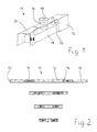
- FIG. 1 shows a perspective view of one end of a Edge shuttering profile element 10 according to German patent application No. 100 02 993.0.
- the profile element 10 consists of a Profile body 12, the different according to the example of Figure 2 Can have lengths.
- a permanent magnet body 14 is attached, one in the middle cylindrical bolt 16 protrudes through an opening in the Top 24 of the profile body 12 protrudes upwards and on has a trigger head 18 at its upper end.
- the permanent magnet body 14 down can be pressed to fix the magnet Profile element 10 on a formwork table 20 (see FIG. 3) bring about.
- two spring elements 22 looking forward to both sides of the bolt 16 on both Permanent magnet body 14 and attached to the profile body 12 are.
- the release head 18 is used to release the permanent magnet body 14 raised, the spring elements 22 thereby relieving themselves act supportive.
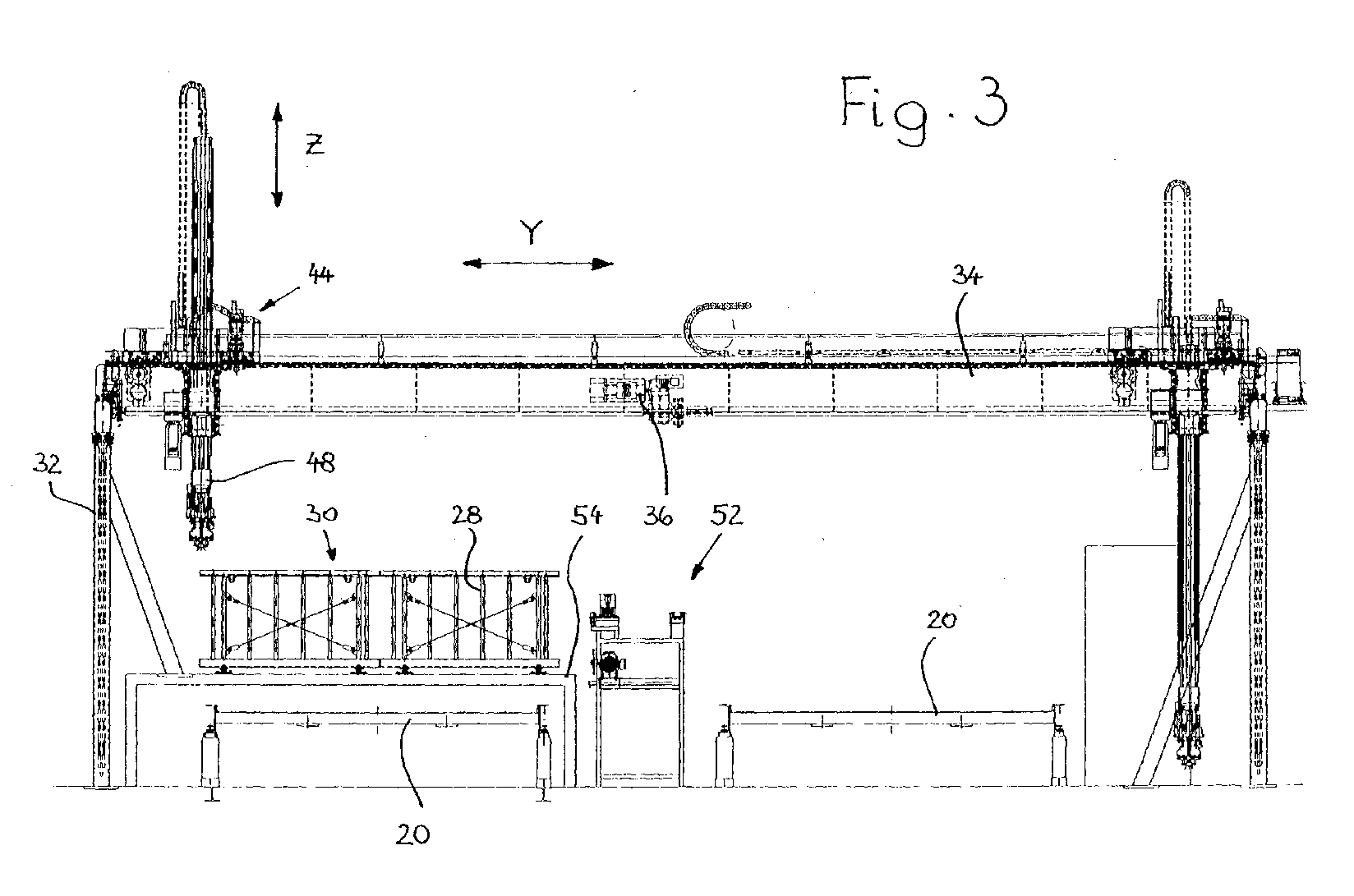
- FIG. 3 to 5 show a device for the production of Precast concrete parts according to the invention.
- This facility exists of two mutually parallel side walls 32, on which one Bridge 34 is movably mounted in the X direction (see FIG. 5).
- a motor 36 which has two half shafts 38, serves as the drive Drives gears 40, which each engage one on the Side walls 32 are attached rack 42.
- a cat 44 can be moved on the bridge 34 in the Y direction stored, the one in the Z-direction lifting and lifting lowerable robot 48 takes.
- About the slewing ring 44 can Robot about its vertical axis of rotation 50 (see FIGS. 6 to 10) be pivoted.
- Figure 2 is in the Y direction between the formwork table 20 and the magazine 30 a cleaning system 52 for used Recognize profile elements 10. It is also shown that the Magazine 30 stands on a trestle 54, under which a formwork table 20 is kept in reserve.
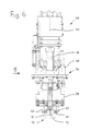
- Figures 6 and 7 show the lower end of the robot 48, the is designed as a gripper head 56.
- the gripper head 56 has two grippers 58 each with two gripping jaws 60 which can be moved relative to one another two gripping jaws 60 are used here to grasp one Profile element 10 with integrated permanent magnet body 14, the profile body 12 on both side legs Has centering recesses 62, in which centering projections 64 the engage both gripper jaws 60.
- Each of the two grippers 58 has two lifting cylinders 66 and is in vertical guides 68 stored.
- the lifting cylinders 66 of a gripper 68 can be used independently controlled by those of the other gripper 58, so that As indicated in Figure 7, two profile elements 10 or others Fixing elements or recess bodies for window openings, Installation parts etc. can be manipulated independently of one another can.
- Each gripper 58 has a limit switch 70 which is in contact with the top 24 of the profile element 10, the drive of Lift cylinder 66 switches off when lowering.
- a centering pin 72 is attached to the gripper 58, which in a recess on the top 24 of the profile element 10 intervenes.
- FIG. 7 shows that 58 between the two grippers an oil spray nozzle 74 is arranged.
- the program-controlled robot 48 removes the data from FIGS a setpoint entered with respect to lengths and Heights of the profile elements 10 the corresponding profile elements from the magazine 30 and transferred them by shifting them in X and Y direction and possibly by pivoting about the axis of rotation 50 the exactly predetermined space on the formwork table 20.
- the permanent magnet body 14 must be activated become.
- the Gripping jaws 60 a setting tool 76. This consists of a Beam 78, which is gripped by the two grippers 58 at the same time and from which a print head 80 protrudes downwards in the middle.
- the setting tool 76 can also be in one of the grippers 58 or in another gripper can be integrated, for example between the two grippers 58 shown in FIG. 8 is arranged controllable independently of these, for example instead of the oil spray nozzle 74 shown there.
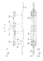
- the Figures 10 to 12 show a possibility according to which the Robot 48 for the unlocking process with a release tool 82 is equipped. This has a release element in the form of a ramp-shaped fork 84 (see FIG. 11), which under the Trigger head 18 can be pushed and this raises it. In this way, the permanent magnet body 14 with Support raised by the spring elements 22 and in the held in a raised position so that the profile element 10 to the side can be removed.
- FIG. 11 shows that in the area of the gripper body 56 in a horizontal guide 86 two slides 88 in opposite directions are movable relative to each other, each one Release tool 82 carries. If the two release tools 82 in Are moved in the direction of the axis of rotation 50, engage ramp-shaped forks 84 under the two release heads 18 so that the profile elements 10 by lifting the Permanent magnet body 14 are unlocked. In this position hold the two forks 84 the profile element 10 during the subsequent onward transport to the cleaning system 52 or in magazine 30.
Landscapes
- Engineering & Computer Science (AREA)
- Chemical & Material Sciences (AREA)
- Ceramic Engineering (AREA)
- Mechanical Engineering (AREA)
- Manufacturing & Machinery (AREA)
- Devices For Post-Treatments, Processing, Supply, Discharge, And Other Processes (AREA)
- Moulds, Cores, Or Mandrels (AREA)
- Crystals, And After-Treatments Of Crystals (AREA)
- Manipulator (AREA)
- Press-Shaping Or Shaping Using Conveyers (AREA)
Abstract
Description
- Figur 1
- eine perspektivische Schemadarstellung eines Endes eines Randabschal-Profilelementes mit integriertem Permanentmagnetkörper,
- Figur 2
- die Unteransicht von vier Profilelementen unterschiedlicher Länge,
- Figur 3
- einen Querschnitt durch eine Einrichtung gemäß der Erfindung,
- Figur 4
- die Längsansicht der Einrichtung gemäß Figur 3,
- Figur 5
- eine Draufsicht auf die Einrichtung der Figuren 3 und 4,
- Figur 6
- in vergrößertem Maßstab die Ansicht eines Roboters im Bereich des Greiferkopfes beim Erfassen eines Profilelementes,
- Figur 7
- die Ansicht des Greiferkopfes mit unabhängig voneinander ansteuerbaren Greifern in Richtung des Pfeiles VII der Figur 6,
- Figur 8
- eine der Figur 7 entsprechende Darstellung des Roboters mit Greifern nach Aufnahme eines Setzwerkzeuges,
- Figur 9
- die um 90° gedrehte Ansicht des Greiferkopfes in Richtung des Pfeiles IX der Figur 8,
- Figur 10
- eine der Figur 3 entsprechende Ansicht der Einrichtung mit Roboter beim Entriegeln der Permanentmagnetköper nach dem Gießen und Aushärten eines Betonfertigteils,
- Figur 11
- in vergrößertem Maßstab die schematische Ansicht des Lösewerkzeugs in Richtung des Pfeiles XI der Figur 10 und
- Figur 12
- eine Draufsicht auf das Lösewerkzeug der Figur 11.
Claims (12)
- Verfahren zur Herstellung von Betonfertigteilen auf mindestens einem Schalungstisch, gekennzeichnet durch die Verwendung wenigstens eines programmgesteuerten Roboters (48), der auf dem Schalungstisch (20) magnetisch fixierbare Randabschal-Profilelemente (10) mit integrierten Permanentmagnetkörpern (14) aus einem Magazin (30) entnimmt, auf dem Schalungstisch (20) lagegenau absetzt und anschließend die Permanentmagnetkörper (14) aktiviert.
- Verfahren nach Anspruch 1, dadurch gekennzeichnet, daß der Roboter (48) die Permanentmagnetkörper (14) mit Hilfe eines vertikal verschiebbaren Setzwerkzeuges (76) aktiviert, das dabei gegen einen von der Oberseite (24) des Profilelementes (10) abstehenden Auslösekopf (18) drückt, der den Permanentmagnetkörper (14) im Profilelement (10) zur Anlage an die Oberseite des Schalungstisches (20) bringt.
- Verfahren nach Anspruch 2, dadurch gekennzeichnet, daß der Roboter (48) nach dem lagegenauen Absetzen aller benötigten Profilelemente (10) das Setzwerkzeug (76) erfaßt oder in Einsatz bringt und alle Permanentmagnetkörper (14) aktiviert.
- Verfahren nach Anspruch 1, dadurch gekennzeichnet, daß nach dem Gießen und der Aushärtung der Betonfertigteile der Roboter (48) die Permanentmagnetkörper (14) entriegelt, die Profilelemente (10) vom Schalungstisch (20) abhebt und diese nach einer Reinigung wieder im Magazin (30) einordnet.
- Verfahren nach Anspruch 4, dadurch gekennzeichnet, daß der Roboter (48) für den Entriegelungsvorgang mit einem Lösewerkzeug (82) bestückt wird, das einen von der Oberseite (24) des Profilelementes (10) abstehenden und mit dem Permanentmagnetkörper (14) verbundenen Auslösekopf (18) anhebt, wodurch der Permanentmagnetkörper (14) in dem Profilelement (10) von der Oberseite des Schalungstisches (20) angehoben wird.
- Verfahren nach Anspruch 5, dadurch gekennzeichnet, daß das Löseerkzeug (82) anschließend auch den Abtransport der Profilelemente (10) durchführt.
- Einrichtung zur Durchführung des Verfahrens nach einem der vorhergehenden Ansprüche mit mindestens einem Schalungstisch und wenigstens einem programmgesteuerten Roboter mit einem um eine vertikale Drehachse schwenkbaren Greiferkopf zum Erfassen von auf dem Schalungstisch magnetisch fixierbaren Randabschal-Profilelementen, dadurch gekennzeichnet, daß der Greiferkopf (56) so ausgebildet ist, daß er die Profilelemente (10), das Setzwerkzeug (76) oder das Lösewerkzeug (82) aufnimmt.
- Einrichtung nach Anspruch 7, dadurch gekennzeichnet, daß das Setzwerkzeug (76) aus einem vom Greiferkopf (56) erfaßbaren Balken (78) besteht, von dem mindestens ein Druckkopf (80) zum Betätigen des Auslösekopfes (18) absteht.
- Einrichtung nach Anspruch 8, dadurch gekennzeichnet, daß der Greiferkopf (56) zwei Greifer (58) zum gleichzeitigen Erfassen eines Profilelementes (10) oder des Balkens (78) des Setzwerkzeuges (76) trägt.
- Einrichtung nach Anspruch 6, dadurch gekennzeichnet, daß das Lösewerkzeug (82) ein unter den Auslösekopf (18) verschiebbares und diesen anhebbares Löseelement hat.
- Einrichtung nach Anspruch 10, dadurch gekennzeichnet, daß das Löseelement als rampenförmige Gabel (84) ausgebildet ist.
- Einrichtung nach Anspruch 10 oder 11, dadurch gekennzeichnet, daß der Greiferkopf (56) zwei gegenläufig verfahrbare Greifer (58) hat, von denen jeder ein Löseelement zum Entriegeln des Auslösekopfes (18) aufnimmt.
Applications Claiming Priority (2)
| Application Number | Priority Date | Filing Date | Title |
|---|---|---|---|
| DE10038757 | 2000-08-09 | ||
| DE10038757A DE10038757B4 (de) | 2000-08-09 | 2000-08-09 | Verfahren zur Herstellung von Betonfertigteilen |
Publications (3)
| Publication Number | Publication Date |
|---|---|
| EP1179401A2 true EP1179401A2 (de) | 2002-02-13 |
| EP1179401A3 EP1179401A3 (de) | 2003-05-21 |
| EP1179401B1 EP1179401B1 (de) | 2006-04-19 |
Family
ID=7651775
Family Applications (1)
| Application Number | Title | Priority Date | Filing Date |
|---|---|---|---|
| EP01112543A Revoked EP1179401B1 (de) | 2000-08-09 | 2001-05-23 | Verfahren und Einrichtung zur Herstellung von Betonfertigteilen |
Country Status (4)
| Country | Link |
|---|---|
| EP (1) | EP1179401B1 (de) |
| AT (1) | ATE323573T1 (de) |
| DE (2) | DE10038757B4 (de) |
| ES (1) | ES2261295T3 (de) |
Cited By (3)
| Publication number | Priority date | Publication date | Assignee | Title |
|---|---|---|---|---|
| EP2527119A2 (de) | 2011-05-25 | 2012-11-28 | Elematic Oy Ab | Verfahren zum Ablösen eines Befestigungsmagnets eines demontierbaren Seitenwandelements mit einem Seitenroboter und Seitenroboter |
| CN102992030A (zh) * | 2011-09-09 | 2013-03-27 | 中国国际海运集装箱(集团)股份有限公司 | 集装箱板材自动上料系统 |
| BE1028897B1 (nl) * | 2020-12-15 | 2022-07-19 | Eeckhout & Dochters Bvba | Werkwijze en inrichting voor de productie van breedvloerplaten |
Families Citing this family (11)
| Publication number | Priority date | Publication date | Assignee | Title |
|---|---|---|---|---|
| DE102006051835B4 (de) * | 2006-11-03 | 2008-07-17 | Weckenmann Anlagentechnik Gmbh & Co. Kg | Schalungsroboteranordnung zur Herstellung von Betonfertigteilen |
| DE102007014254A1 (de) | 2007-03-24 | 2008-09-25 | Sommer Anlagentechnik Gmbh | Verfahren und Einrichtung zum Positionieren von Randabschal-Profilelementen auf einem Schalungstisch |
| PL2323823T3 (pl) * | 2008-08-13 | 2014-03-31 | Hoegskolen I Vestfold | Zautomatyzowane wytwarzanie wielkowymiarowych elementów powłokowych w przypadku materiałów podlegających wiązaniu |
| AT507211B1 (de) | 2009-01-07 | 2010-03-15 | Schlackl Franz | Vorrichtung zum herstellen von betonträgern, insbesondere deckenträgern |
| DE102010000664A1 (de) | 2010-01-05 | 2011-07-07 | Sommer Anlagentechnik GmbH, 84051 | Anlage zur Herstellung von Betonfertigteilen |
| DE202012100153U1 (de) | 2012-01-17 | 2012-02-23 | Sommer Anlagentechnik Gmbh | Vorrichtung zum Greifen und Vereinzeln von Bauteilen |
| DE202012103100U1 (de) | 2012-08-17 | 2012-09-11 | Sommer Anlagentechnik Gmbh | Systemschalungseinrichtung für Innenkonturen von Betonfertigteilen |
| DE202017100638U1 (de) | 2017-02-07 | 2017-02-21 | Vollert Anlagenbau Gmbh | Reinigungsstation |
| WO2018171893A1 (de) | 2017-03-24 | 2018-09-27 | Sommer Anlagentechnik Gmbh | Vorrichtung zum fixieren von betonwandelementen in einer schalung |
| DE102019200400A1 (de) * | 2019-01-15 | 2020-07-16 | Herbert Wintersteiger | Verfahren und Vorrichtung zur Positionierung und/oder Entfernung von Fixierungselementen auf/von einer Schalungsunterlage, sowie Fixierungselement zur Verwendung in Kombination mit der Vorrichtung, sowohl einzeln als auch in Kombination als System |
| DE102020126483B4 (de) | 2020-10-09 | 2022-09-08 | B.T. Innovation Gmbh | Schaltbare Magnetvorrichtung und System, umfassend ein Gehäuse und eine schaltbare Magnetvorrichtung |
Family Cites Families (7)
| Publication number | Priority date | Publication date | Assignee | Title |
|---|---|---|---|---|
| JP3158287B2 (ja) * | 1991-05-13 | 2001-04-23 | 旭化成株式会社 | 可動仕切板の移動装置 |
| DE4129368C2 (de) * | 1991-09-04 | 1997-09-11 | Weckenmann Anlagentechnik Gmbh | Einrichtung zur Herstellung von Betonfertigteilen |
| DE9410444U1 (de) * | 1994-06-29 | 1994-08-25 | Weckenmann Anlagentechnik GmbH, 72358 Dormettingen | Einrichtung zur Herstellung von Betonfertigteilen |
| DE19651933C1 (de) * | 1996-12-14 | 1997-11-27 | Ebawe Maschinenbau Gmbh | Verfahren zum Einschalen von Betonfertigteil-Formen mit einem Schalungsroboter |
| DE10002993A1 (de) * | 1999-09-24 | 2000-07-06 | Georg Weidner | Stapelbare Fixiervorrichtung für Schalungszwecke |
| DE29920866U1 (de) * | 1999-12-01 | 2000-01-27 | Reymann Technik GmbH, 68766 Hockenheim | Schalungssystem für Betonfertigteile |
| AT5819U1 (de) * | 2001-12-12 | 2002-12-27 | Ebawe Anlagentechnik Gmbh | Einrichtung zum anheben und/oder zum transport und/oder zum absetzen mindestens eines schalungselementes |
-
2000
- 2000-08-09 DE DE10038757A patent/DE10038757B4/de not_active Expired - Fee Related
-
2001
- 2001-05-23 DE DE50109531T patent/DE50109531D1/de not_active Revoked
- 2001-05-23 AT AT01112543T patent/ATE323573T1/de active
- 2001-05-23 EP EP01112543A patent/EP1179401B1/de not_active Revoked
- 2001-05-23 ES ES01112543T patent/ES2261295T3/es not_active Expired - Lifetime
Cited By (6)
| Publication number | Priority date | Publication date | Assignee | Title |
|---|---|---|---|---|
| EP2527119A2 (de) | 2011-05-25 | 2012-11-28 | Elematic Oy Ab | Verfahren zum Ablösen eines Befestigungsmagnets eines demontierbaren Seitenwandelements mit einem Seitenroboter und Seitenroboter |
| CN102794818A (zh) * | 2011-05-25 | 2012-11-28 | 艾乐迈铁科公司 | 侧机器人及其使可拆卸侧壁单元的紧固磁体脱离的方法 |
| EP2527119A3 (de) * | 2011-05-25 | 2014-04-30 | Elematic Oy Ab | Verfahren zum Ablösen eines Befestigungsmagnets eines demontierbaren Seitenwandelements mit einem Seitenroboter und Seitenroboter |
| CN102992030A (zh) * | 2011-09-09 | 2013-03-27 | 中国国际海运集装箱(集团)股份有限公司 | 集装箱板材自动上料系统 |
| CN102992030B (zh) * | 2011-09-09 | 2015-04-29 | 中国国际海运集装箱(集团)股份有限公司 | 集装箱板材自动上料系统 |
| BE1028897B1 (nl) * | 2020-12-15 | 2022-07-19 | Eeckhout & Dochters Bvba | Werkwijze en inrichting voor de productie van breedvloerplaten |
Also Published As
| Publication number | Publication date |
|---|---|
| DE10038757B4 (de) | 2012-10-18 |
| EP1179401A3 (de) | 2003-05-21 |
| ES2261295T3 (es) | 2006-11-16 |
| DE50109531D1 (de) | 2006-05-24 |
| EP1179401B1 (de) | 2006-04-19 |
| ATE323573T1 (de) | 2006-05-15 |
| DE10038757A1 (de) | 2002-02-21 |
Similar Documents
| Publication | Publication Date | Title |
|---|---|---|
| DE3320762C2 (de) | Stanzmaschine mit einem stationären Magazin | |
| EP1179401A2 (de) | Verfahren und Einrichtung zur Herstellung von Betonfertigteilen | |
| DE3049495C2 (de) | ||
| EP3231552B1 (de) | Werkstückpositioniervorrichtung für ein bearbeitungszentrum, bearbeitungszentrum und verfahren | |
| EP0530504B1 (de) | Verfahren und Einrichtung zur Herstellung von Betonteilen | |
| EP2117781B1 (de) | Manipulator für die beladung wenigstens einer maschine, insbesondere werkzeugmaschine, sowie beladevorrichtung für eine derartige maschine | |
| EP3031572A1 (de) | Werkzeugwechselvorrichtung zur verwendung in einem bearbeitungszentrum und bearbeitungszentrum zur maschinellen bearbeitung eines werkstücks | |
| EP2881219B1 (de) | Werkzeugwechselvorrichtung zur Verwendung in einem Bearbeitungszentrum und Bearbeitungszentrum zur maschinellen Bearbeitung eines Werkstücks | |
| DE19500614A1 (de) | Revolverstanzvorrichtung | |
| DE1201245B (de) | Vorrichtung zum Foerdern eines Werkstueckes | |
| EP3664959B1 (de) | Verfahren und vorrichtung zur bereitstellung von schrauben | |
| EP0290469B1 (de) | Vorrichtung zum automatischen bearbeiten unterschiedlich geformterwerkstücke | |
| EP0480191A2 (de) | Vorrichtung zum Bearbeiten von Stangen | |
| EP3683025A1 (de) | Verfahren und vorrichtung zur positionierung und/oder entfernung von fixierungselementen auf/von einer schalungsunterlage, sowie fixierungselement zur verwendung in kombination mit der vorrichtung, sowohl einzeln als auch in kombination als system | |
| DE3036333C2 (de) | Vorrichtung zur Entnahme von Werkstücken an einer Druck- oder Spritzgießmaschine | |
| DE102011012953A1 (de) | Vorrichtung zur maschinellen Handhabung von Trays | |
| DE2821709C2 (de) | Vorrichtung zum Abbau und Wiederzusammenbau eines aus mehreren Segmenten bestehenden Laufflächenringes | |
| AT522423B1 (de) | Magazin für Einlegeteile | |
| DE102017106179A1 (de) | Etagenwerkzeug | |
| DE4333944A1 (de) | Verfahren und Vorrichtung zum Herstellen eines Rades, insbesondere eines vorzugweise vorgeformten Eisenbahnrades | |
| DE3326055A1 (de) | Ueberfuehrungseinrichtung fuer schmiedemaschinen | |
| WO2023011727A1 (de) | Rüststation für eine werkstückpalette sowie werkstückpalette | |
| DE3050099C2 (de) | Vorrichtung zur Herstellung von Werkstücken durch Druck- oder Spritzgießen | |
| DE202024106928U1 (de) | Spritzgießmaschine mit Drehtisch für Mittelplattentransport | |
| DE1602719C (de) | Werkzeugwechselvorrichtung für eine Werkzeugmaschine |
Legal Events
| Date | Code | Title | Description |
|---|---|---|---|
| PUAI | Public reference made under article 153(3) epc to a published international application that has entered the european phase |
Free format text: ORIGINAL CODE: 0009012 |
|
| AK | Designated contracting states |
Kind code of ref document: A2 Designated state(s): AT BE CH CY DE DK ES FI FR GB GR IE IT LI LU MC NL PT SE TR |
|
| AX | Request for extension of the european patent |
Free format text: AL;LT;LV;MK;RO;SI |
|
| PUAL | Search report despatched |
Free format text: ORIGINAL CODE: 0009013 |
|
| AK | Designated contracting states |
Designated state(s): AT BE CH CY DE DK ES FI FR GB GR IE IT LI LU MC NL PT SE TR |
|
| AX | Request for extension of the european patent |
Extension state: AL LT LV MK RO SI |
|
| 17P | Request for examination filed |
Effective date: 20030920 |
|
| AKX | Designation fees paid |
Designated state(s): AT BE CH CY DE DK ES FI FR GB GR IE IT LI LU MC NL PT SE TR |
|
| GRAP | Despatch of communication of intention to grant a patent |
Free format text: ORIGINAL CODE: EPIDOSNIGR1 |
|
| GRAS | Grant fee paid |
Free format text: ORIGINAL CODE: EPIDOSNIGR3 |
|
| GRAA | (expected) grant |
Free format text: ORIGINAL CODE: 0009210 |
|
| AK | Designated contracting states |
Kind code of ref document: B1 Designated state(s): AT BE CH CY DE DK ES FI FR GB GR IE IT LI LU MC NL PT SE TR |
|
| PG25 | Lapsed in a contracting state [announced via postgrant information from national office to epo] |
Ref country code: FI Free format text: LAPSE BECAUSE OF FAILURE TO SUBMIT A TRANSLATION OF THE DESCRIPTION OR TO PAY THE FEE WITHIN THE PRESCRIBED TIME-LIMIT Effective date: 20060419 |
|
| RAP1 | Party data changed (applicant data changed or rights of an application transferred) |
Owner name: SOMMER ANLAGENTECHNIK GMBH |
|
| REG | Reference to a national code |
Ref country code: GB Ref legal event code: FG4D Free format text: NOT ENGLISH |
|
| REF | Corresponds to: |
Ref document number: 50109531 Country of ref document: DE Date of ref document: 20060524 Kind code of ref document: P |
|
| PG25 | Lapsed in a contracting state [announced via postgrant information from national office to epo] |
Ref country code: MC Free format text: LAPSE BECAUSE OF NON-PAYMENT OF DUE FEES Effective date: 20060531 Ref country code: LI Free format text: LAPSE BECAUSE OF NON-PAYMENT OF DUE FEES Effective date: 20060531 Ref country code: CH Free format text: LAPSE BECAUSE OF NON-PAYMENT OF DUE FEES Effective date: 20060531 |
|
| REG | Reference to a national code |
Ref country code: IE Ref legal event code: FG4D Free format text: LANGUAGE OF EP DOCUMENT: GERMAN |
|
| PG25 | Lapsed in a contracting state [announced via postgrant information from national office to epo] |
Ref country code: DK Free format text: LAPSE BECAUSE OF FAILURE TO SUBMIT A TRANSLATION OF THE DESCRIPTION OR TO PAY THE FEE WITHIN THE PRESCRIBED TIME-LIMIT Effective date: 20060719 Ref country code: SE Free format text: LAPSE BECAUSE OF FAILURE TO SUBMIT A TRANSLATION OF THE DESCRIPTION OR TO PAY THE FEE WITHIN THE PRESCRIBED TIME-LIMIT Effective date: 20060719 |
|
| GBT | Gb: translation of ep patent filed (gb section 77(6)(a)/1977) |
Effective date: 20060704 |
|
| PG25 | Lapsed in a contracting state [announced via postgrant information from national office to epo] |
Ref country code: PT Free format text: LAPSE BECAUSE OF FAILURE TO SUBMIT A TRANSLATION OF THE DESCRIPTION OR TO PAY THE FEE WITHIN THE PRESCRIBED TIME-LIMIT Effective date: 20060919 |
|
| REG | Reference to a national code |
Ref country code: ES Ref legal event code: FG2A Ref document number: 2261295 Country of ref document: ES Kind code of ref document: T3 |
|
| ET | Fr: translation filed | ||
| REG | Reference to a national code |
Ref country code: CH Ref legal event code: PL |
|
| PLBI | Opposition filed |
Free format text: ORIGINAL CODE: 0009260 |
|
| PLAX | Notice of opposition and request to file observation + time limit sent |
Free format text: ORIGINAL CODE: EPIDOSNOBS2 |
|
| 26 | Opposition filed |
Opponent name: AVERMANN MASCHINENFABRIK GMBH & CO.KG Effective date: 20070118 |
|
| PGFP | Annual fee paid to national office [announced via postgrant information from national office to epo] |
Ref country code: IE Payment date: 20070403 Year of fee payment: 7 |
|
| PGFP | Annual fee paid to national office [announced via postgrant information from national office to epo] |
Ref country code: LU Payment date: 20070418 Year of fee payment: 7 |
|
| NLR1 | Nl: opposition has been filed with the epo |
Opponent name: AVERMANN MASCHINENFABRIK GMBH & CO.KG |
|
| PLAF | Information modified related to communication of a notice of opposition and request to file observations + time limit |
Free format text: ORIGINAL CODE: EPIDOSCOBS2 |
|
| PLBB | Reply of patent proprietor to notice(s) of opposition received |
Free format text: ORIGINAL CODE: EPIDOSNOBS3 |
|
| PG25 | Lapsed in a contracting state [announced via postgrant information from national office to epo] |
Ref country code: GR Free format text: LAPSE BECAUSE OF FAILURE TO SUBMIT A TRANSLATION OF THE DESCRIPTION OR TO PAY THE FEE WITHIN THE PRESCRIBED TIME-LIMIT Effective date: 20060720 |
|
| PG25 | Lapsed in a contracting state [announced via postgrant information from national office to epo] |
Ref country code: TR Free format text: LAPSE BECAUSE OF FAILURE TO SUBMIT A TRANSLATION OF THE DESCRIPTION OR TO PAY THE FEE WITHIN THE PRESCRIBED TIME-LIMIT Effective date: 20060419 |
|
| PG25 | Lapsed in a contracting state [announced via postgrant information from national office to epo] |
Ref country code: CY Free format text: LAPSE BECAUSE OF FAILURE TO SUBMIT A TRANSLATION OF THE DESCRIPTION OR TO PAY THE FEE WITHIN THE PRESCRIBED TIME-LIMIT Effective date: 20060419 |
|
| RDAF | Communication despatched that patent is revoked |
Free format text: ORIGINAL CODE: EPIDOSNREV1 |
|
| PG25 | Lapsed in a contracting state [announced via postgrant information from national office to epo] |
Ref country code: IE Free format text: LAPSE BECAUSE OF NON-PAYMENT OF DUE FEES Effective date: 20080523 |
|
| APBM | Appeal reference recorded |
Free format text: ORIGINAL CODE: EPIDOSNREFNO |
|
| APBP | Date of receipt of notice of appeal recorded |
Free format text: ORIGINAL CODE: EPIDOSNNOA2O |
|
| APAH | Appeal reference modified |
Free format text: ORIGINAL CODE: EPIDOSCREFNO |
|
| APBQ | Date of receipt of statement of grounds of appeal recorded |
Free format text: ORIGINAL CODE: EPIDOSNNOA3O |
|
| PGFP | Annual fee paid to national office [announced via postgrant information from national office to epo] |
Ref country code: ES Payment date: 20090520 Year of fee payment: 9 Ref country code: NL Payment date: 20090529 Year of fee payment: 9 |
|
| PLBP | Opposition withdrawn |
Free format text: ORIGINAL CODE: 0009264 |
|
| PGFP | Annual fee paid to national office [announced via postgrant information from national office to epo] |
Ref country code: AT Payment date: 20090518 Year of fee payment: 9 Ref country code: FR Payment date: 20090530 Year of fee payment: 9 |
|
| PGFP | Annual fee paid to national office [announced via postgrant information from national office to epo] |
Ref country code: GB Payment date: 20090520 Year of fee payment: 9 |
|
| PG25 | Lapsed in a contracting state [announced via postgrant information from national office to epo] |
Ref country code: LU Free format text: LAPSE BECAUSE OF NON-PAYMENT OF DUE FEES Effective date: 20080523 |
|
| APBU | Appeal procedure closed |
Free format text: ORIGINAL CODE: EPIDOSNNOA9O |
|
| PGFP | Annual fee paid to national office [announced via postgrant information from national office to epo] |
Ref country code: IT Payment date: 20100526 Year of fee payment: 10 |
|
| RDAG | Patent revoked |
Free format text: ORIGINAL CODE: 0009271 |
|
| STAA | Information on the status of an ep patent application or granted ep patent |
Free format text: STATUS: PATENT REVOKED |
|
| PGFP | Annual fee paid to national office [announced via postgrant information from national office to epo] |
Ref country code: BE Payment date: 20100518 Year of fee payment: 10 |
|
| 27W | Patent revoked |
Effective date: 20100812 |
|
| GBPR | Gb: patent revoked under art. 102 of the ep convention designating the uk as contracting state |
Effective date: 20100812 |
|
| PGFP | Annual fee paid to national office [announced via postgrant information from national office to epo] |
Ref country code: DE Payment date: 20100729 Year of fee payment: 10 |
|
| PG25 | Lapsed in a contracting state [announced via postgrant information from national office to epo] |
Ref country code: ES Free format text: LAPSE BECAUSE OF NON-PAYMENT OF DUE FEES Effective date: 20100524 |