EP1179448A2 - Dispositif d'éclairage pour écran plat et procédé de fabrication - Google Patents
Dispositif d'éclairage pour écran plat et procédé de fabrication Download PDFInfo
- Publication number
- EP1179448A2 EP1179448A2 EP01118670A EP01118670A EP1179448A2 EP 1179448 A2 EP1179448 A2 EP 1179448A2 EP 01118670 A EP01118670 A EP 01118670A EP 01118670 A EP01118670 A EP 01118670A EP 1179448 A2 EP1179448 A2 EP 1179448A2
- Authority
- EP
- European Patent Office
- Prior art keywords
- layer
- lighting device
- electroluminescent
- electrode
- electroluminescent layer
- Prior art date
- Legal status (The legal status is an assumption and is not a legal conclusion. Google has not performed a legal analysis and makes no representation as to the accuracy of the status listed.)
- Withdrawn
Links
Images


Classifications
-
- G—PHYSICS
- G01—MEASURING; TESTING
- G01D—MEASURING NOT SPECIALLY ADAPTED FOR A SPECIFIC VARIABLE; ARRANGEMENTS FOR MEASURING TWO OR MORE VARIABLES NOT COVERED IN A SINGLE OTHER SUBCLASS; TARIFF METERING APPARATUS; MEASURING OR TESTING NOT OTHERWISE PROVIDED FOR
- G01D11/00—Component parts of measuring arrangements not specially adapted for a specific variable
- G01D11/28—Structurally-combined illuminating devices
-
- B—PERFORMING OPERATIONS; TRANSPORTING
- B60—VEHICLES IN GENERAL
- B60K—ARRANGEMENT OR MOUNTING OF PROPULSION UNITS OR OF TRANSMISSIONS IN VEHICLES; ARRANGEMENT OR MOUNTING OF PLURAL DIVERSE PRIME-MOVERS IN VEHICLES; AUXILIARY DRIVES FOR VEHICLES; INSTRUMENTATION OR DASHBOARDS FOR VEHICLES; ARRANGEMENTS IN CONNECTION WITH COOLING, AIR INTAKE, GAS EXHAUST OR FUEL SUPPLY OF PROPULSION UNITS IN VEHICLES
- B60K35/00—Instruments specially adapted for vehicles; Arrangement of instruments in or on vehicles
- B60K35/20—Output arrangements, i.e. from vehicle to user, associated with vehicle functions or specially adapted therefor
- B60K35/21—Output arrangements, i.e. from vehicle to user, associated with vehicle functions or specially adapted therefor using visual output, e.g. blinking lights or matrix displays
- B60K35/215—Output arrangements, i.e. from vehicle to user, associated with vehicle functions or specially adapted therefor using visual output, e.g. blinking lights or matrix displays characterised by the combination of multiple visual outputs, e.g. combined instruments with analogue meters and additional displays
-
- B—PERFORMING OPERATIONS; TRANSPORTING
- B60—VEHICLES IN GENERAL
- B60K—ARRANGEMENT OR MOUNTING OF PROPULSION UNITS OR OF TRANSMISSIONS IN VEHICLES; ARRANGEMENT OR MOUNTING OF PLURAL DIVERSE PRIME-MOVERS IN VEHICLES; AUXILIARY DRIVES FOR VEHICLES; INSTRUMENTATION OR DASHBOARDS FOR VEHICLES; ARRANGEMENTS IN CONNECTION WITH COOLING, AIR INTAKE, GAS EXHAUST OR FUEL SUPPLY OF PROPULSION UNITS IN VEHICLES
- B60K35/00—Instruments specially adapted for vehicles; Arrangement of instruments in or on vehicles
- B60K35/60—Instruments characterised by their location or relative disposition in or on vehicles
-
- B—PERFORMING OPERATIONS; TRANSPORTING
- B60—VEHICLES IN GENERAL
- B60K—ARRANGEMENT OR MOUNTING OF PROPULSION UNITS OR OF TRANSMISSIONS IN VEHICLES; ARRANGEMENT OR MOUNTING OF PLURAL DIVERSE PRIME-MOVERS IN VEHICLES; AUXILIARY DRIVES FOR VEHICLES; INSTRUMENTATION OR DASHBOARDS FOR VEHICLES; ARRANGEMENTS IN CONNECTION WITH COOLING, AIR INTAKE, GAS EXHAUST OR FUEL SUPPLY OF PROPULSION UNITS IN VEHICLES
- B60K37/00—Dashboards
- B60K37/20—Dashboard panels
-
- B—PERFORMING OPERATIONS; TRANSPORTING
- B60—VEHICLES IN GENERAL
- B60Q—ARRANGEMENT OF SIGNALLING OR LIGHTING DEVICES, THE MOUNTING OR SUPPORTING THEREOF OR CIRCUITS THEREFOR, FOR VEHICLES IN GENERAL
- B60Q3/00—Arrangement of lighting devices for vehicle interiors; Lighting devices specially adapted for vehicle interiors
- B60Q3/10—Arrangement of lighting devices for vehicle interiors; Lighting devices specially adapted for vehicle interiors for dashboards
- B60Q3/14—Arrangement of lighting devices for vehicle interiors; Lighting devices specially adapted for vehicle interiors for dashboards lighting through the surface to be illuminated
-
- H—ELECTRICITY
- H10—SEMICONDUCTOR DEVICES; ELECTRIC SOLID-STATE DEVICES NOT OTHERWISE PROVIDED FOR
- H10K—ORGANIC ELECTRIC SOLID-STATE DEVICES
- H10K59/00—Integrated devices, or assemblies of multiple devices, comprising at least one organic light-emitting element covered by group H10K50/00
-
- B—PERFORMING OPERATIONS; TRANSPORTING
- B60—VEHICLES IN GENERAL
- B60K—ARRANGEMENT OR MOUNTING OF PROPULSION UNITS OR OF TRANSMISSIONS IN VEHICLES; ARRANGEMENT OR MOUNTING OF PLURAL DIVERSE PRIME-MOVERS IN VEHICLES; AUXILIARY DRIVES FOR VEHICLES; INSTRUMENTATION OR DASHBOARDS FOR VEHICLES; ARRANGEMENTS IN CONNECTION WITH COOLING, AIR INTAKE, GAS EXHAUST OR FUEL SUPPLY OF PROPULSION UNITS IN VEHICLES
- B60K2360/00—Indexing scheme associated with groups B60K35/00 or B60K37/00 relating to details of instruments or dashboards
- B60K2360/20—Optical features of instruments
- B60K2360/33—Illumination features
-
- H—ELECTRICITY
- H10—SEMICONDUCTOR DEVICES; ELECTRIC SOLID-STATE DEVICES NOT OTHERWISE PROVIDED FOR
- H10K—ORGANIC ELECTRIC SOLID-STATE DEVICES
- H10K59/00—Integrated devices, or assemblies of multiple devices, comprising at least one organic light-emitting element covered by group H10K50/00
- H10K59/10—OLED displays
- H10K59/221—Static displays, e.g. displaying permanent logos
-
- H—ELECTRICITY
- H10—SEMICONDUCTOR DEVICES; ELECTRIC SOLID-STATE DEVICES NOT OTHERWISE PROVIDED FOR
- H10K—ORGANIC ELECTRIC SOLID-STATE DEVICES
- H10K59/00—Integrated devices, or assemblies of multiple devices, comprising at least one organic light-emitting element covered by group H10K50/00
- H10K59/80—Constructional details
- H10K59/805—Electrodes
Definitions
- the invention relates to a lighting device for a area display and a method for producing a Lighting device.
- the light valve, especially in the form of a liquid crystal display Disadvantage that even when switched through Losses of light arise which affect the luminous efficacy of the Reduce backlighting.
- an emissive ad has the advantage that thus immediately switchable in some areas Backlighting can be formed, creating a additional light valve can be saved.
- the display device consists of a carrier with at least one electrode, the contour of the Display is adapted, another electrode and one arranged in between, dielectric with embedded, in alternating electrical field of the electrodes luminescent Pigments and a transparent, the display side of the Facility forming cover. Building this Display device is particularly simple because Carries a conventional printed circuit board with etched electrodes is used.
- the electroluminescent layer comes in such a structure generally only one Electroluminescent film into consideration.
- Electroluminescent films for many areas of application in Inadequate luminance with regard to display units to reach.
- the invention has for its object a Illumination device for a flat display unit to provide that for common uses offers sufficient brightness and with which comparatively low manufacturing technology Manufacturing expenses independently controllable sub-areas let it be realized.
- the invention is based on one Lighting device for a flat display unit, which is a carrier substrate and arranged thereon one above the other Includes electrodes, between which there is one electroluminescent layer is located.
- the core idea of Invention is now that the electroluminescent Layer is an organic electroluminescent layer. This allows significantly higher luminance levels in the after as before the comparatively simple structure of the Reach lighting device. Because the organic Electroluminescent material can be easily manufacturing processes on a carrier substrate apply, e.g. by spinning or pouring.
- the selection of only individual areas of the electroluminescent layer can by accordingly structured electrodes can be achieved.
- At least one electrode and the electroluminescent organic layer for laying down a light-emitting surface partially by an electrical insulating layer separated. This is done in an elegant way a determination of the emissive area of the Lighting device reached. Because in places where the separating insulating layer is present Current flow through the electroluminescent layer and thus prevented from lighting up.
- the structure is particularly easy when the Structure the insulating layer yourself photolithographically leaves. This is for example with photoresist layers or the case with photosensitive polyimides.
- the carrier substrate be made of plastic consists.
- Electrodes are preferably facing a display unit Electrodes divided several times and transparent.
- Humidity is also suggested to be on the the carrier substrate arranged layer structure with a Protective cover, e.g. a glass substrate.
- Another essential aspect of the invention is included a method for manufacturing a lighting device for a flat display unit, in which on a Carrier substrate a first electrode layer made of electrical conductive material is deposited, then a layer of organic electroluminescent material is applied and another after the electroluminescent layer Electrode layer deposited from electrically conductive material being, either between the first electrode layer and the electroluminescent layer and / or between the electroluminescent layer and the second Electrode layer is an electrically insulating layer is applied and structured.
- An electrode layer is preferably used in the production, advantageously the second overhead in general transparent electrode layer, e.g. from ITO (indium tin Oxide) consists of several independently controllable Divided electrode areas. Let through this measure parts of the lighting device are independent of each other switch on and off or dim.
- ITO indium tin Oxide
- FIG. 1 shows the schematic structure of a Combination instrument 1 in a vehicle.
- the Combination instrument 1 comprises a circuit board 2 on the the control electronics of the various components of the Combination instrument are arranged. About it is a Carrier substrate 3 with independently controllable areas 4, 5 made of organic electroluminescent material positioned.
- the tasks of the carrier substrate 3 could also be taken over from the circuit board 2. That the organic electroluminescent material would then immediately turn on applied the circuit board. It could as well Carrier substrate 3 form a unit with the printed circuit board 2.
- the carrier substrate 3 could be a thin film be designed.
- a dial 6 is arranged above the carrier substrate 3, which usually consists of a plastic film and transmissive surfaces 7, 8 and absorbent surfaces 9 has.
- the transmissive surfaces 7, 8 are, for example designed as numbers, tick marks or symbols.
- the Electroluminescent areas 4, 5 are directly behind the transmissive surfaces 7, 8 positioned and preferably at least the same size or overlap these areas. By leave the organic electroluminescent regions 4, 5 comparatively large luminance levels can be achieved the use of a arranged above the dial 6 Darkening mask 10 allowed.
- the darkening mask 10 is in the Generally a few centimeters above the dial 6 attached and also has the function of a protective screen.
- Figure 2 illustrates the layer structure of a organic electroluminescent lighting device 21, in particular backlighting device for a Display unit, e.g. a combination instrument 1.
- the backlighting device 21 can be used as detailed illustration for the carrier substrate 3 and the electroluminescent areas 4, 5 can be understood.
- the backlight device 21 consists of a Glass substrate 11 on which a continuous electrode 12 is applied. One sits on the electrode 12 electroluminescent layer 13 by a structured photoresist layer 14 is covered. Thereon follows one into several independently controllable partial electrodes 15, 16 structured ITO layer 17. ITO (indium tin oxide or in German indium tin oxide) is known in a commonly used layer thickness transparent, what that of the organic electroluminescent layer emitted light allowed on this side the Leave backlight device 21.
- the electrode 12 has advantageously for an effective light output reflective properties.
- a protective cover in the form of e.g. one further glass substrates 18 attached.
- the layer structure of the backlighting device 21 are in With regard to the invention in particular two aspects again highlight.
- the structured photoresist layer it becomes easy to see the emissive areas, that when a voltage is applied between the electrodes 12 and emit 15 or 16 light, in an exact manner set.
- the underlying organic electroluminescent Layer electrically insulated, causing the layer to light up prevented.
- the photoresist-free areas 19, 20 emit light when a voltage is applied.
- the region 19 lights up.
- the application of a voltage between the electrodes 12 and 16 leads to the region 20 of the electroluminescent layer lighting up.
- the photoresist layer can thus be used to predefine emissive structures in a simple manner, with the independently controllable electrode regions 15, 16 making it possible to independently select the emissive surfaces of the electroluminescent layer defined by the photoresist structure. This means that the areas 19, 20 can be switched on or off independently or dimmed if desired. Dimming is usually done with pulse width modulation.
- the organic electroluminescent layer 13 combines the advantage of an area light source that saves a light distribution system with the possibility of achieving a sufficiently high luminance, for example 100 cd / m 2 , which cannot be achieved, in particular, by an electroluminescent film.
- FIG. 3a shows a tachometer 30 with a dial 31 and a speedometer needle 32 and an LCD display 33 for the Display of the mileage shown.
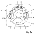
- Figure 3b is an inventive Backlighting device 35 for the speedometer 30 in one schematic top view.
- the backlight device 35 includes a cut-out carrier substrate 36 on which one not divided by the dash-dotted line shown base electrode 37 from e.g. ITO is applied. This is followed by a continuous organic electroluminescent layer by a photoresist layer 38 covered with a plurality of recesses 39, 40, 41 is.
- the recesses 39 are the graduations 42, the Cutouts 40 the numbers 43, the cutout 41 is the Kilometer display 33 and the recess 44 the center of the Speedometer needle 32 deposited.
- the recesses 39, 40, 41, 44 the areas are defined in which the organic electroluminescent layer by means of a counter electrode can be lit when voltage is applied.
- the counter electrodes 45, 46, 47, 48, 49 necessary for this are shown in solid lines.
- the counter electrodes 45, 46, 47, 48, 49 and the rest Electrodes can be controlled separately.
- Photoresist layer can thus the exact structure of the Luminaire areas can be defined using the separately controllable counter electrodes independently with different control voltage can be applied. In order to can be found on the dial of the speedometer 30 different speed ranges different luminosity of the scale lines 42 optically highlight.
- a certain speed range in which e.g. one cruise control is active compared to the rest Dial can be illuminated brighter or darker to a to obtain optical differentiation.
Landscapes
- Engineering & Computer Science (AREA)
- Mechanical Engineering (AREA)
- Chemical & Material Sciences (AREA)
- Combustion & Propulsion (AREA)
- Transportation (AREA)
- Physics & Mathematics (AREA)
- General Physics & Mathematics (AREA)
- Electroluminescent Light Sources (AREA)
- Illuminated Signs And Luminous Advertising (AREA)
- Details Of Measuring Devices (AREA)
- Arrangements Of Lighting Devices For Vehicle Interiors, Mounting And Supporting Thereof, Circuits Therefore (AREA)
Applications Claiming Priority (2)
| Application Number | Priority Date | Filing Date | Title |
|---|---|---|---|
| DE10038762A DE10038762B4 (de) | 2000-08-09 | 2000-08-09 | Beleuchtungsvorrichtung für eine flächige Anzeige |
| DE10038762 | 2000-08-09 |
Publications (2)
| Publication Number | Publication Date |
|---|---|
| EP1179448A2 true EP1179448A2 (fr) | 2002-02-13 |
| EP1179448A3 EP1179448A3 (fr) | 2006-09-20 |
Family
ID=7651780
Family Applications (1)
| Application Number | Title | Priority Date | Filing Date |
|---|---|---|---|
| EP01118670A Withdrawn EP1179448A3 (fr) | 2000-08-09 | 2001-08-03 | Dispositif d'éclairage pour écran plat et procédé de fabrication |
Country Status (2)
| Country | Link |
|---|---|
| EP (1) | EP1179448A3 (fr) |
| DE (1) | DE10038762B4 (fr) |
Cited By (3)
| Publication number | Priority date | Publication date | Assignee | Title |
|---|---|---|---|---|
| EP1458221A3 (fr) * | 2003-03-14 | 2005-08-17 | Siemens Aktiengesellschaft | Corps moulé en plastique capable d'être illuminé et procédé de fabrication |
| EP1589265A1 (fr) * | 2004-04-19 | 2005-10-26 | Delphi Technologies, Inc. | Dispositif d'éclairage |
| WO2007011414A3 (fr) * | 2004-11-12 | 2007-03-15 | Du Pont | Ecran sans pixel |
Families Citing this family (3)
| Publication number | Priority date | Publication date | Assignee | Title |
|---|---|---|---|---|
| DE102011016423A1 (de) * | 2011-04-08 | 2012-10-11 | GM Global Technology Operations LLC (n. d. Gesetzen des Staates Delaware) | Anzeigeinstrument und Verfahren zum Betreiben eines Anzeigeinstruments |
| DE102012005076A1 (de) * | 2012-03-13 | 2013-09-19 | GM Global Technology Operations LLC (n. d. Gesetzen des Staates Delaware) | Instrumententafel für eine Kraftfahrzeug |
| DE102018133306A1 (de) | 2018-12-21 | 2020-06-25 | Bayerische Motoren Werke Aktiengesellschaft | Kraftfahrzeugbauteil mit Leuchtfunktion |
Citations (2)
| Publication number | Priority date | Publication date | Assignee | Title |
|---|---|---|---|---|
| DE4023693A1 (de) | 1989-09-20 | 1991-03-28 | Helmut Moser | Anzeigeeinrichtung mit elektrolumineszierender beleuchtung |
| DE19540813C1 (de) | 1995-07-19 | 1996-09-05 | Vdo Schindling | Anzeigeeinheit |
Family Cites Families (4)
| Publication number | Priority date | Publication date | Assignee | Title |
|---|---|---|---|---|
| DE19502542A1 (de) * | 1995-01-27 | 1996-08-08 | Bosch Gmbh Robert | Anzeigeeinrichtung, insbesondere für Kraftfahrzeuge |
| US5902688A (en) * | 1996-07-16 | 1999-05-11 | Hewlett-Packard Company | Electroluminescent display device |
| US5977704A (en) * | 1996-10-28 | 1999-11-02 | Motorola, Inc. | Organic electroluminescent display with icons |
| TW432896B (en) * | 1997-10-15 | 2001-05-01 | Siemens Ag | Preparation of organic electroluminescencizing elements |
-
2000
- 2000-08-09 DE DE10038762A patent/DE10038762B4/de not_active Expired - Fee Related
-
2001
- 2001-08-03 EP EP01118670A patent/EP1179448A3/fr not_active Withdrawn
Patent Citations (2)
| Publication number | Priority date | Publication date | Assignee | Title |
|---|---|---|---|---|
| DE4023693A1 (de) | 1989-09-20 | 1991-03-28 | Helmut Moser | Anzeigeeinrichtung mit elektrolumineszierender beleuchtung |
| DE19540813C1 (de) | 1995-07-19 | 1996-09-05 | Vdo Schindling | Anzeigeeinheit |
Cited By (4)
| Publication number | Priority date | Publication date | Assignee | Title |
|---|---|---|---|---|
| EP1458221A3 (fr) * | 2003-03-14 | 2005-08-17 | Siemens Aktiengesellschaft | Corps moulé en plastique capable d'être illuminé et procédé de fabrication |
| EP1589265A1 (fr) * | 2004-04-19 | 2005-10-26 | Delphi Technologies, Inc. | Dispositif d'éclairage |
| US7699483B2 (en) | 2004-04-19 | 2010-04-20 | Delphi Technologies, Inc. | Illumination device |
| WO2007011414A3 (fr) * | 2004-11-12 | 2007-03-15 | Du Pont | Ecran sans pixel |
Also Published As
| Publication number | Publication date |
|---|---|
| EP1179448A3 (fr) | 2006-09-20 |
| DE10038762A1 (de) | 2002-02-28 |
| DE10038762B4 (de) | 2009-01-02 |
Similar Documents
| Publication | Publication Date | Title |
|---|---|---|
| DE19732119B4 (de) | Zusammengesetzte Anzeigetafel | |
| DE69902656T2 (de) | Elektrolumineszierende vorrichtung | |
| DE69713376T2 (de) | Elektrolumineszierende hintergrundbeleuchtete anordnungen | |
| EP1015269B1 (fr) | Dispositif d'affichage | |
| DE19547375B4 (de) | Anzeigeeinrichtung | |
| EP0382879A1 (fr) | Instrument muni d'une aiguille | |
| EP1046944A2 (fr) | Dispositif LCD auto éclairé | |
| DE4034015A1 (de) | Leuchtzeigernadelvorrichtung fuer fahrzeuganzeigeinstrument | |
| EP1045462B1 (fr) | Diode organique émettrice de lumière pour produire de la lumière à couleurs mixtes | |
| EP0805956B1 (fr) | Systeme d'affichage, notamment pour automobiles | |
| DE10246920B4 (de) | Kraftfahrzeugmeßgerät mit einem beleuchteten Zeiger | |
| EP1179448A2 (fr) | Dispositif d'éclairage pour écran plat et procédé de fabrication | |
| DE102017220355A1 (de) | Vorrichtung und fahrzeug | |
| DE112019004769B4 (de) | Grafikanzeigebaugruppe zur Darstellung einer Fahrzeugschaltvorrichtungsstellung | |
| DE10220335B4 (de) | Anzeigeeinrichtung | |
| DE10209622B4 (de) | Optische Anzeige | |
| DE102006023658A1 (de) | Funktionsintegrierte LCD-Anzeigen mit OLED-Backlight | |
| EP1767986A1 (fr) | Dispositif d'affichage monochromatique retroéclairé, véhicule automobile et procédé de commande du dispositif d'affichage monochromatique | |
| DE102017102321A1 (de) | Displayanordnung | |
| DE10046237A1 (de) | Zeigeranzeigevorrichtung und entsprechendes Herstellungsverfahren | |
| DE2320142C3 (de) | Armaturenbrett mit Vorrichtung zur Beleuchtung | |
| EP3259150B1 (fr) | Panneau de commande dans un véhicule automobile | |
| EP2795396B1 (fr) | Dispositif d'affichage muni d'un module d'affichage électro-optique | |
| DE112006001629T5 (de) | Dünner Instrumentenblock mit Antireflexbeschichtung | |
| EP1103943A2 (fr) | Dispositif optique d'affichage d'informations |
Legal Events
| Date | Code | Title | Description |
|---|---|---|---|
| PUAI | Public reference made under article 153(3) epc to a published international application that has entered the european phase |
Free format text: ORIGINAL CODE: 0009012 |
|
| AK | Designated contracting states |
Kind code of ref document: A2 Designated state(s): AT BE CH CY DE DK ES FI FR GB GR IE IT LI LU MC NL PT SE TR |
|
| AX | Request for extension of the european patent |
Free format text: AL;LT;LV;MK;RO;SI |
|
| PUAL | Search report despatched |
Free format text: ORIGINAL CODE: 0009013 |
|
| AK | Designated contracting states |
Kind code of ref document: A3 Designated state(s): AT BE CH CY DE DK ES FI FR GB GR IE IT LI LU MC NL PT SE TR |
|
| AX | Request for extension of the european patent |
Extension state: AL LT LV MK RO SI |
|
| AKX | Designation fees paid | ||
| STAA | Information on the status of an ep patent application or granted ep patent |
Free format text: STATUS: THE APPLICATION IS DEEMED TO BE WITHDRAWN |
|
| 18D | Application deemed to be withdrawn |
Effective date: 20070321 |
|
| REG | Reference to a national code |
Ref country code: DE Ref legal event code: 8566 |