EP1179466A2 - Chariot de manutention avec un dispositif de ramassage de charges - Google Patents
Chariot de manutention avec un dispositif de ramassage de charges Download PDFInfo
- Publication number
- EP1179466A2 EP1179466A2 EP01119132A EP01119132A EP1179466A2 EP 1179466 A2 EP1179466 A2 EP 1179466A2 EP 01119132 A EP01119132 A EP 01119132A EP 01119132 A EP01119132 A EP 01119132A EP 1179466 A2 EP1179466 A2 EP 1179466A2
- Authority
- EP
- European Patent Office
- Prior art keywords
- suspension device
- industrial truck
- load suspension
- control unit
- lifting height
- Prior art date
- Legal status (The legal status is an assumption and is not a legal conclusion. Google has not performed a legal analysis and makes no representation as to the accuracy of the status listed.)
- Granted
Links
- 239000000725 suspension Substances 0.000 claims description 52
- 235000004443 Ricinus communis Nutrition 0.000 description 1
- 240000000528 Ricinus communis Species 0.000 description 1
- 239000010720 hydraulic oil Substances 0.000 description 1
- 238000005192 partition Methods 0.000 description 1
Images
Classifications
-
- B—PERFORMING OPERATIONS; TRANSPORTING
- B62—LAND VEHICLES FOR TRAVELLING OTHERWISE THAN ON RAILS
- B62B—HAND-PROPELLED VEHICLES, e.g. HAND CARTS OR PERAMBULATORS; SLEDGES
- B62B3/00—Hand carts having more than one axis carrying transport wheels; Steering devices therefor; Equipment therefor
- B62B3/04—Hand carts having more than one axis carrying transport wheels; Steering devices therefor; Equipment therefor involving means for grappling or securing in place objects to be carried; Loading or unloading equipment
- B62B3/06—Hand carts having more than one axis carrying transport wheels; Steering devices therefor; Equipment therefor involving means for grappling or securing in place objects to be carried; Loading or unloading equipment for simply clearing the load from the ground
- B62B3/0612—Hand carts having more than one axis carrying transport wheels; Steering devices therefor; Equipment therefor involving means for grappling or securing in place objects to be carried; Loading or unloading equipment for simply clearing the load from the ground power operated
-
- B—PERFORMING OPERATIONS; TRANSPORTING
- B66—HOISTING; LIFTING; HAULING
- B66F—HOISTING, LIFTING, HAULING OR PUSHING, NOT OTHERWISE PROVIDED FOR, e.g. DEVICES WHICH APPLY A LIFTING OR PUSHING FORCE DIRECTLY TO THE SURFACE OF A LOAD
- B66F9/00—Devices for lifting or lowering bulky or heavy goods for loading or unloading purposes
- B66F9/06—Devices for lifting or lowering bulky or heavy goods for loading or unloading purposes movable, with their loads, on wheels or the like, e.g. fork-lift trucks
- B66F9/075—Constructional features or details
- B66F9/20—Means for actuating or controlling masts, platforms, or forks
- B66F9/24—Electrical devices or systems
Definitions
- the invention relates to an industrial truck, preferably a pallet truck or Low-level order picker, with a load handling device and an electrical one Control unit for controlling a vertical movement of the load suspension device, with at least one setpoint for the lifting height of the control unit Load suspension device is adjustable and with the control unit at least one Control element for controlling an upward movement of the load suspension device in Active connection is established.
- the invention also relates to an industrial truck, preferably Pallet truck or low level order picker, with a liftable Load suspension device and an electrical control unit for controlling a vertical movement of the load suspension device, with the control unit at least one control element for controlling a downward movement of the Load suspension device is in operative connection.
- Industrial trucks of the type mentioned can be used as pedestrian vehicles, Stand-alone vehicles or driver seat vehicles.
- the Industrial trucks have a load suspension device with which, for example, Loads formed on pallets can be lifted.
- the one for lifting the loads Required force is usually generated by means of a hydraulic cylinder an electro-hydraulic pump unit is supplied with hydraulic oil.
- this pump unit by means of Controls for controlling the upward movement can be switched on and off can.
- To lower the load suspension device one with the Hydraulic cylinder connected valve can be opened, which with the Control element for controlling the downward movement can be controlled.
- the operator has to set the desired lifting height precisely a certain level of practice, as there are usually no tools available for this.
- the invention is therefore based on the object of making an industrial truck available make one or more setpoints for the upward movement in simple Way can be controlled. Another object of the invention is a To provide the truck, by means of an operating element complete lowering of the load suspension device can be specifically selected.
- control unit in such a way is carried out depending on the operating time of the control element a setpoint for the lifting height can be specified to control the upward movement. Because only the operating time, but not the operating force for the Setting the setpoint is decisive, the setpoint for the lifting height can also be used Gloves can be set correctly.
- control unit is designed such that in Dependence on the duration of actuation of the control element to control the Upward movement either a first setpoint or a second setpoint can be specified is.
- the Control unit which setpoint for the lifting height is desired.
- the The load suspension device is then automatically up to the selected setpoint raised and then stopped in that position.
- the lifting movement is up to Reaching the setpoint continues even when the control element is no longer is operated.
- the arrangement according to the invention enables the preselection of Setpoints for the lifting height depending on the actuation time for this provided control element.
- the control unit is set to a first setpoint when the actuation period of the control element for controlling the upward movement is shorter than one in the Control unit stored period of time.
- the lifting height is at a second setpoint set when the operating time of the control element to control the Upward movement is longer than a time period stored in the control unit.
- This time period preferably has a value between 0.5 seconds and 1 Second on.
- the first setpoint specifies a value between 30 mm and 50 mm for the lifting height. At this lifting height, one is picked up with the load suspension device Pallet slightly raised from the road surface so that it moves can be. With this low lifting height, however, it is possible that the pallet, e.g. with uneven road, still touching the ground.
- a stroke height between 100 mm and 140 mm is specified as the second setpoint. This lifting height is selected for the transport of a pallet over long distances.
- the Control unit is designed such that during an operation of the second Control element an upward movement takes place provided the maximum lifting height has not yet been reached.
- This design of the control unit corresponds to the classic one Arrangement in which an electrohydraulic pump unit by means of Controls can be turned on and off. The second control thus enables manual control of the lifting movement.
- the second object is achieved according to the invention in that the Control unit is designed such that, depending on the duration of actuation of the Controls to control the downward movement a complete lowering of the Load suspension device can be predetermined. With this control for the Lowering movement, the control device can be controlled such that the Load suspension device is automatically lowered completely. The attention the operator is not watching the lowering movement Load suspension device claimed, since it is ensured that the Load suspension device always reaches its lowest position.
- the load suspension device is lowered completely when the actuation period of the control element for controlling the upward movement is longer than one in the Control unit stored second time period. This can result in incorrect operation, e.g. by inadvertently pressing the control element.
- the second time period preferably has a value between 0.5 seconds and 1.5 Seconds on.
- the downward movement of the load suspension device can be carried out by the operator be stopped if the control element after the specification of a complete Lowering the load suspension device is operated a second time.
- the automatic downward movement of the load handler from the Operator can be stopped at any time.
- a second control element for controlling a downward movement is provided, the control unit being designed in such a way that during an actuation of the second control element a downward movement takes place if the minimum lifting height has not yet been reached.
- This second Control element can manually move the load handler down to be controlled.
- This function corresponds to the classic arrangement in which a hydraulic valve can be opened and closed using the control element can.
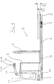
- FIG. 2 shows a low-lift order picker as an industrial truck according to the invention.
- the low-level order picker has a drive part 1 that cannot be raised and one Load part 2 that can be raised relative to drive part 1.
- the load part 2 consists in Essentially from a battery compartment 3, a driver platform 4, a partition 5 and a load suspension device 6 designed as a load fork.
- the load part 2 stands in the area of the load suspension device with load rollers 7 on the carriageway 8, the distance between the load rollers 7 and the load suspension device 6 is not by means of a shown linkage can be changed.
- the drive part 1 is in this Embodiment by means of a steerable drive wheel 9 around two castors 10 on the road 8.
- a steering drawbar 11 is also arranged on the drive part 1, whereby Rotating the steering drawbar 11 about a substantially vertical axis Steering movement of the drive wheel 9 can be controlled.
- a Drawbar head 12 of the steering drawbar are controls for the various functions of the low-level order picker, being on the top the tiller head 12 a total of four controls 13-16 for controlling the vertical movement of the load handler are arranged.
- This Operating elements 13-16 are provided with a control unit arranged in the drive part 1 17 in operative connection.
- the control unit 17 contains two setpoints for the lifting height of the Load suspension device 6 stored, on which the load suspension device 6 at corresponding actuation of the controls 13 to 16 is automatically set. Starting from the lowest position, the first setpoint corresponds to Load suspension device 6, a lifting height of 40 mm. The second setpoint corresponds a lifting height of 120 mm and thus the maximum lifting height. The positions of the Load suspension device 6 at the two setpoints is with dashed lines clarified.
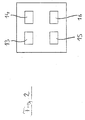
- FIG. 2 shows the arrangement of the operating elements 13-16 designed as push buttons shown for the load suspension device 6.
- the in the control device 17th Saved functionality is as follows:
- An automatic lifting function can be actuated with the control element 13. If the control element 13 briefly, e.g. pressed for approx. 0.5 seconds and then again is released, the load suspension device 6 automatically rises to one Lifting height of 40 mm. If the control element 13 is long, e.g. about 1 second is actuated, the load suspension device automatically rises to a lifting height from 120 mm. To switch between a short and a long press to be able to distinguish, a time period is stored in the control device 17, e.g. has a value of 0.8 seconds. With this saved period of time the actual operating time of the control element 13 is compared and by the Control device 17 selected the corresponding setpoint for the lifting height. The automatic upward movement of the load suspension device 6 can be stopped be when the control element 13 is operated a second time before the Load suspension device 6 has reached the selected setpoint for the lifting height.
- An automatic lowering function can be actuated with the control element 14. If the control element 14 longer than one stored in the control device 17 Time period is pressed, the load handler 6 automatically lowers completely from.
- the stored time period can also have a value of 0.8, for example Seconds, but can also be set to a different value. According to a safety function, the automatic downward movement of the Load suspension device 6 can be stopped when the control element 14 is on is operated a second time before the load suspension device reaches its lowest position has reached.
- the operator can vertical movement manually control the load suspension device 6 in a conventional manner.
- the load suspension device 6 is raised, until the control element 15 is released again or reaches the upper end position is.
- Load suspension device 6 lowered until the operating element 16 is released again or the lowest position of the load suspension device is reached.
Landscapes
- Engineering & Computer Science (AREA)
- Transportation (AREA)
- Chemical & Material Sciences (AREA)
- Combustion & Propulsion (AREA)
- Mechanical Engineering (AREA)
- Structural Engineering (AREA)
- Civil Engineering (AREA)
- Life Sciences & Earth Sciences (AREA)
- Geology (AREA)
- Forklifts And Lifting Vehicles (AREA)
- Vehicle Body Suspensions (AREA)
Applications Claiming Priority (2)
| Application Number | Priority Date | Filing Date | Title |
|---|---|---|---|
| DE10039382 | 2000-08-11 | ||
| DE2000139382 DE10039382A1 (de) | 2000-08-11 | 2000-08-11 | Flurförderzeug mit einer Lastaufnahmevorrichtung |
Publications (3)
| Publication Number | Publication Date |
|---|---|
| EP1179466A2 true EP1179466A2 (fr) | 2002-02-13 |
| EP1179466A3 EP1179466A3 (fr) | 2003-09-24 |
| EP1179466B1 EP1179466B1 (fr) | 2007-04-11 |
Family
ID=7652187
Family Applications (1)
| Application Number | Title | Priority Date | Filing Date |
|---|---|---|---|
| EP20010119132 Expired - Lifetime EP1179466B1 (fr) | 2000-08-11 | 2001-08-08 | Chariot de manutention avec un dispositif de ramassage de charges |
Country Status (2)
| Country | Link |
|---|---|
| EP (1) | EP1179466B1 (fr) |
| DE (2) | DE10039382A1 (fr) |
Cited By (2)
| Publication number | Priority date | Publication date | Assignee | Title |
|---|---|---|---|---|
| EP3072777A1 (fr) * | 2015-03-27 | 2016-09-28 | Jungheinrich Aktiengesellschaft | Chariot de manutention, notamment transpalette |
| US10430073B2 (en) | 2015-07-17 | 2019-10-01 | Crown Equipment Corporation | Processing device having a graphical user interface for industrial vehicle |
Families Citing this family (4)
| Publication number | Priority date | Publication date | Assignee | Title |
|---|---|---|---|---|
| DE102008015503B4 (de) | 2008-03-25 | 2023-06-22 | Linde Material Handling Gmbh | Flurförderzeug mit einem Fahrerstandschutz |
| BR112017003874A2 (pt) | 2014-09-15 | 2018-01-23 | Crown Equip Corp | empilhadeira. |
| WO2018098025A1 (fr) | 2016-11-22 | 2018-05-31 | Crown Equipment Corporation | Dispositif d'interface utilisateur pour véhicule industriel |
| DE102017104507A1 (de) | 2017-03-03 | 2018-09-06 | Jungheinrich Aktiengesellschaft | Flurförderzeug mit einem Antriebsrahmen und einem in der Höhe verstellbaren Lastrahmen |
Citations (1)
| Publication number | Priority date | Publication date | Assignee | Title |
|---|---|---|---|---|
| EP0812799A1 (fr) | 1996-06-14 | 1997-12-17 | Still Wagner GmbH & Co. KG | Elément de contrÔle pour chariot de manutention guidé par timon |
Family Cites Families (3)
| Publication number | Priority date | Publication date | Assignee | Title |
|---|---|---|---|---|
| FR1315457A (fr) * | 1962-02-19 | 1963-01-18 | Dispositif de levage et déplacement spécialement pour plates-formes élévatrices | |
| DE4306680C2 (de) * | 1993-03-04 | 1995-02-16 | Jungheinrich Ag | Verfahren zur Bestimmung der Hubhöhe eines höhenverstellbaren Lastaufnahmemittels eines Flurförderzeugs |
| DE19528415A1 (de) * | 1995-08-02 | 1997-02-06 | Linde Ag | Verfahren zum Betreiben eines Flurförderzeugs und dafür vorgesehenes Flurförderzeug |
-
2000
- 2000-08-11 DE DE2000139382 patent/DE10039382A1/de not_active Withdrawn
-
2001
- 2001-08-08 EP EP20010119132 patent/EP1179466B1/fr not_active Expired - Lifetime
- 2001-08-08 DE DE50112315T patent/DE50112315D1/de not_active Expired - Lifetime
Patent Citations (1)
| Publication number | Priority date | Publication date | Assignee | Title |
|---|---|---|---|---|
| EP0812799A1 (fr) | 1996-06-14 | 1997-12-17 | Still Wagner GmbH & Co. KG | Elément de contrÔle pour chariot de manutention guidé par timon |
Cited By (2)
| Publication number | Priority date | Publication date | Assignee | Title |
|---|---|---|---|---|
| EP3072777A1 (fr) * | 2015-03-27 | 2016-09-28 | Jungheinrich Aktiengesellschaft | Chariot de manutention, notamment transpalette |
| US10430073B2 (en) | 2015-07-17 | 2019-10-01 | Crown Equipment Corporation | Processing device having a graphical user interface for industrial vehicle |
Also Published As
| Publication number | Publication date |
|---|---|
| DE10039382A1 (de) | 2002-02-21 |
| EP1179466A3 (fr) | 2003-09-24 |
| DE50112315D1 (de) | 2007-05-24 |
| EP1179466B1 (fr) | 2007-04-11 |
Similar Documents
| Publication | Publication Date | Title |
|---|---|---|
| EP1030816B1 (fr) | Chariot de manutention, en particulier appareil preparateur des commandes | |
| EP1527980A1 (fr) | Dispositif pour le système de direction d'un charriot élévateur | |
| DE3150476C2 (fr) | ||
| DE3402495A1 (de) | Deichselgelenktes foerdergeraet | |
| EP0812799B1 (fr) | Elément de contrôle pour chariot de manutention guidé par timon | |
| DE19935008A1 (de) | Gabelniederhubwagen | |
| EP1179466B1 (fr) | Chariot de manutention avec un dispositif de ramassage de charges | |
| EP0773136B1 (fr) | Plate-forme de hayon et procédé pour sa commande | |
| EP0792791B1 (fr) | Chariot de manutention avec une plate-forme pour être assis et/ou debout et réglable en hauteur | |
| DE4306680C2 (de) | Verfahren zur Bestimmung der Hubhöhe eines höhenverstellbaren Lastaufnahmemittels eines Flurförderzeugs | |
| EP0931758B1 (fr) | Chariot élévateur avec un dispositif d'amortissement des chocs | |
| EP1243490A1 (fr) | Chariot de manutention entraíné par batterie | |
| DE102007017052A1 (de) | Hubwagen | |
| DE4226936C1 (de) | Flurförderzeug, insbesondere fahrerloses Fahrzeug | |
| DE4428010A1 (de) | Flurförderzeug mit einem Hubgerüst | |
| DE19634216C2 (de) | Lastaufnahmemittel zur doppeltiefen Ein- beziehungsweise Auslagerung von palletierten Ladeeinheiten | |
| EP1622443B1 (fr) | Dispositif et procede de commande du systeme de levage d'un vehicule agricole | |
| EP1707467A2 (fr) | Chariot de manutention à petite hauteur de levage | |
| EP3502042B1 (fr) | Flotte de chariots de manutention | |
| EP3072777B1 (fr) | Chariot de manutention, notamment transpalette | |
| DE2259003C3 (de) | Sicherheitsvorrichtung für landwirtschaftliche Maschinen mit hydraulisch höhenverstellbarer Arbeitsplattform | |
| DE889276C (de) | Gewichtsarmer Fahrstapler | |
| DE102006022746A1 (de) | Stehsitz mit Bedienelementen | |
| DE102024119167A1 (de) | Flurförderzeug mit Multifunktionselement | |
| DE4440399A1 (de) | Gabelstapler |
Legal Events
| Date | Code | Title | Description |
|---|---|---|---|
| PUAI | Public reference made under article 153(3) epc to a published international application that has entered the european phase |
Free format text: ORIGINAL CODE: 0009012 |
|
| AK | Designated contracting states |
Kind code of ref document: A2 Designated state(s): AT BE CH CY DE DK ES FI FR GB GR IE IT LI LU MC NL PT SE TR |
|
| AX | Request for extension of the european patent |
Free format text: AL;LT;LV;MK;RO;SI |
|
| RAP1 | Party data changed (applicant data changed or rights of an application transferred) |
Owner name: STILL S.A.R.L. |
|
| PUAL | Search report despatched |
Free format text: ORIGINAL CODE: 0009013 |
|
| AK | Designated contracting states |
Kind code of ref document: A3 Designated state(s): AT BE CH CY DE DK ES FI FR GB GR IE IT LI LU MC NL PT SE TR |
|
| AX | Request for extension of the european patent |
Extension state: AL LT LV MK RO SI |
|
| 17P | Request for examination filed |
Effective date: 20040302 |
|
| AKX | Designation fees paid |
Designated state(s): DE FR GB IT SE |
|
| GRAP | Despatch of communication of intention to grant a patent |
Free format text: ORIGINAL CODE: EPIDOSNIGR1 |
|
| GRAS | Grant fee paid |
Free format text: ORIGINAL CODE: EPIDOSNIGR3 |
|
| GRAA | (expected) grant |
Free format text: ORIGINAL CODE: 0009210 |
|
| AK | Designated contracting states |
Kind code of ref document: B1 Designated state(s): DE FR GB IT SE |
|
| REG | Reference to a national code |
Ref country code: GB Ref legal event code: FG4D Free format text: NOT ENGLISH |
|
| REF | Corresponds to: |
Ref document number: 50112315 Country of ref document: DE Date of ref document: 20070524 Kind code of ref document: P |
|
| PG25 | Lapsed in a contracting state [announced via postgrant information from national office to epo] |
Ref country code: SE Free format text: LAPSE BECAUSE OF FAILURE TO SUBMIT A TRANSLATION OF THE DESCRIPTION OR TO PAY THE FEE WITHIN THE PRESCRIBED TIME-LIMIT Effective date: 20070711 |
|
| GBV | Gb: ep patent (uk) treated as always having been void in accordance with gb section 77(7)/1977 [no translation filed] |
Effective date: 20070411 |
|
| EN | Fr: translation not filed | ||
| PLBE | No opposition filed within time limit |
Free format text: ORIGINAL CODE: 0009261 |
|
| STAA | Information on the status of an ep patent application or granted ep patent |
Free format text: STATUS: NO OPPOSITION FILED WITHIN TIME LIMIT |
|
| REG | Reference to a national code |
Ref country code: GB Ref legal event code: 710B Free format text: EXTENSION APPLICATION: APPLICATION FOR EXTENSION OF THE PERIOD(S) PRESCRIBED BY RULE(S) 68(2) FILED ON 20080114 |
|
| 26N | No opposition filed |
Effective date: 20080114 |
|
| PG25 | Lapsed in a contracting state [announced via postgrant information from national office to epo] |
Ref country code: GB Free format text: LAPSE BECAUSE OF FAILURE TO SUBMIT A TRANSLATION OF THE DESCRIPTION OR TO PAY THE FEE WITHIN THE PRESCRIBED TIME-LIMIT Effective date: 20070411 Ref country code: FR Free format text: LAPSE BECAUSE OF FAILURE TO SUBMIT A TRANSLATION OF THE DESCRIPTION OR TO PAY THE FEE WITHIN THE PRESCRIBED TIME-LIMIT Effective date: 20071207 |
|
| PGFP | Annual fee paid to national office [announced via postgrant information from national office to epo] |
Ref country code: FR Payment date: 20070927 Year of fee payment: 7 |
|
| REG | Reference to a national code |
Ref country code: FR Ref legal event code: RN |
|
| REG | Reference to a national code |
Ref country code: GB Ref legal event code: R108 Effective date: 20070410 |
|
| REG | Reference to a national code |
Ref country code: SE Ref legal event code: TRGR |
|
| PGFP | Annual fee paid to national office [announced via postgrant information from national office to epo] |
Ref country code: SE Payment date: 20080519 Year of fee payment: 8 |
|
| PGRI | Patent reinstated in contracting state [announced from national office to epo] |
Ref country code: GB Effective date: 20080410 |
|
| PGFP | Annual fee paid to national office [announced via postgrant information from national office to epo] |
Ref country code: GB Payment date: 20080822 Year of fee payment: 8 |
|
| PGRI | Patent reinstated in contracting state [announced from national office to epo] |
Ref country code: GB Effective date: 20080410 |
|
| REG | Reference to a national code |
Ref country code: FR Ref legal event code: IC |
|
| REG | Reference to a national code |
Ref country code: FR Ref legal event code: RU |
|
| GBPC | Gb: european patent ceased through non-payment of renewal fee |
Effective date: 20090808 |
|
| PG25 | Lapsed in a contracting state [announced via postgrant information from national office to epo] |
Ref country code: SE Free format text: LAPSE BECAUSE OF FAILURE TO SUBMIT A TRANSLATION OF THE DESCRIPTION OR TO PAY THE FEE WITHIN THE PRESCRIBED TIME-LIMIT Effective date: 20090809 |
|
| PGFP | Annual fee paid to national office [announced via postgrant information from national office to epo] |
Ref country code: IT Payment date: 20090819 Year of fee payment: 9 |
|
| REG | Reference to a national code |
Ref country code: FR Ref legal event code: JE |
|
| PG25 | Lapsed in a contracting state [announced via postgrant information from national office to epo] |
Ref country code: GB Free format text: LAPSE BECAUSE OF NON-PAYMENT OF DUE FEES Effective date: 20090808 |
|
| PGFP | Annual fee paid to national office [announced via postgrant information from national office to epo] |
Ref country code: DE Payment date: 20100922 Year of fee payment: 10 |
|
| PG25 | Lapsed in a contracting state [announced via postgrant information from national office to epo] |
Ref country code: IT Free format text: LAPSE BECAUSE OF NON-PAYMENT OF DUE FEES Effective date: 20100808 |
|
| PG25 | Lapsed in a contracting state [announced via postgrant information from national office to epo] |
Ref country code: DE Free format text: LAPSE BECAUSE OF NON-PAYMENT OF DUE FEES Effective date: 20130301 |
|
| REG | Reference to a national code |
Ref country code: DE Ref legal event code: R119 Ref document number: 50112315 Country of ref document: DE Effective date: 20130301 |
|
| REG | Reference to a national code |
Ref country code: DE Ref legal event code: R082 Ref document number: 50112315 Country of ref document: DE Representative=s name: PATENTSHIP PATENTANWALTSGESELLSCHAFT MBH, DE |
|
| REG | Reference to a national code |
Ref country code: DE Ref legal event code: R082 Ref document number: 50112315 Country of ref document: DE Representative=s name: PATENTSHIP PATENTANWALTSGESELLSCHAFT MBH, DE |