EP1179647A2 - Verstellbare Arbeitsbühne - Google Patents
Verstellbare Arbeitsbühne Download PDFInfo
- Publication number
- EP1179647A2 EP1179647A2 EP01117351A EP01117351A EP1179647A2 EP 1179647 A2 EP1179647 A2 EP 1179647A2 EP 01117351 A EP01117351 A EP 01117351A EP 01117351 A EP01117351 A EP 01117351A EP 1179647 A2 EP1179647 A2 EP 1179647A2
- Authority
- EP
- European Patent Office
- Prior art keywords
- building
- attached
- work platform
- base plate
- railing
- Prior art date
- Legal status (The legal status is an assumption and is not a legal conclusion. Google has not performed a legal analysis and makes no representation as to the accuracy of the status listed.)
- Granted
Links
Images




Classifications
-
- E—FIXED CONSTRUCTIONS
- E04—BUILDING
- E04G—SCAFFOLDING; FORMS; SHUTTERING; BUILDING IMPLEMENTS OR AIDS, OR THEIR USE; HANDLING BUILDING MATERIALS ON THE SITE; REPAIRING, BREAKING-UP OR OTHER WORK ON EXISTING BUILDINGS
- E04G3/00—Scaffolds essentially supported by building constructions, e.g. adjustable in height
- E04G3/24—Scaffolds essentially supported by building constructions, e.g. adjustable in height specially adapted for particular parts of buildings or for buildings of particular shape, e.g. chimney stacks or pylons
-
- E—FIXED CONSTRUCTIONS
- E04—BUILDING
- E04G—SCAFFOLDING; FORMS; SHUTTERING; BUILDING IMPLEMENTS OR AIDS, OR THEIR USE; HANDLING BUILDING MATERIALS ON THE SITE; REPAIRING, BREAKING-UP OR OTHER WORK ON EXISTING BUILDINGS
- E04G3/00—Scaffolds essentially supported by building constructions, e.g. adjustable in height
- E04G3/20—Scaffolds essentially supported by building constructions, e.g. adjustable in height supported by walls
-
- E—FIXED CONSTRUCTIONS
- E04—BUILDING
- E04G—SCAFFOLDING; FORMS; SHUTTERING; BUILDING IMPLEMENTS OR AIDS, OR THEIR USE; HANDLING BUILDING MATERIALS ON THE SITE; REPAIRING, BREAKING-UP OR OTHER WORK ON EXISTING BUILDINGS
- E04G3/00—Scaffolds essentially supported by building constructions, e.g. adjustable in height
- E04G3/24—Scaffolds essentially supported by building constructions, e.g. adjustable in height specially adapted for particular parts of buildings or for buildings of particular shape, e.g. chimney stacks or pylons
- E04G3/243—Scaffolds essentially supported by building constructions, e.g. adjustable in height specially adapted for particular parts of buildings or for buildings of particular shape, e.g. chimney stacks or pylons following the outside contour of a building
-
- E—FIXED CONSTRUCTIONS
- E04—BUILDING
- E04G—SCAFFOLDING; FORMS; SHUTTERING; BUILDING IMPLEMENTS OR AIDS, OR THEIR USE; HANDLING BUILDING MATERIALS ON THE SITE; REPAIRING, BREAKING-UP OR OTHER WORK ON EXISTING BUILDINGS
- E04G3/00—Scaffolds essentially supported by building constructions, e.g. adjustable in height
- E04G3/28—Mobile scaffolds; Scaffolds with mobile platforms
Definitions
- the invention relates to one in the construction of buildings, in particular Circular buildings with a circular shape, reflecting the height of the building in their Diameter changing outer contour, usable on the outside of the building Working platform which surrounds the outside of the building Basic structure with adjustable, on the outside diameter of the building adjustable supports, via which the work platform can be attached to the building wall and a stage floor supported by the basic structure, at least comprises a base plate which is displaceable relative to the basic structure, and a has railings attached to the outer periphery of the work platform.
- Such reinforced concrete structures are manufactured, for example, using climbing formwork.
- the essence of such climbing formwork is that here the masonry penetrating formwork anchors are to be provided on and with which Formwork elements are braced in their entirety, with one Concreting step each anchored in concrete above as a foot anchor for the formwork can be used in the next concreting step. In every concreting step a new anchor is then installed. It must be assumed that that the formwork is sufficiently rigid over its height. The formwork will then raised when the previous concrete section of the wall has set has the entire weight of the formwork over the formwork anchors has to carry.
- the formwork itself consists of the actual formwork panels and the scaffold stiffening the formwork panels. For structures whose through If the knife changes over the height, special climbing formwork has already been used changeable diameter proposed.
- the object of the invention is an improved work platform of the aforementioned Art to provide that, along with their stage floor in a simple manner is adaptable to different outside diameters of the building wall, wherein also the railing required on the outside of the work platform is simple and is stably attachable.
- the basic structure Trolleys are attached, each of which has at least one pair of rollers have, whose two rollers are freely rotatable, and that at the Undersides of the floor panels of the stage floor are attached to profile rails a horizontal web and laterally arranged on this, downward Include sidewalls, the lower free ends of which are angled inward are and form horizontally inward projections, the rails each take at least a pair of rollers of a trolley and are slidable along these and with the profile rails the outside of the work platform facing away from the outer wall of the building protrude over the edge of the respective base plate and on the protruding Section of the profile rail attached to a support post of the railing is.
- the base plates of the stage floor can in the work platform according to the invention to adapt to the outside diameter of the building wall in simple Wise offset by the bottom plates with those on their undersides attached profile rails moved on the rollers of the trolleys become.
- the one on the outside of the work platform over the edge of each Sections of the profiled rails projecting from the base plate serve by means of support posts attached to them for secure mounting or support of the railing.
- the work platform is in Floor plan is hexagonal, with the horizontal points at the corners inside, slidable carrier are arranged. Conveniently lie each in the area between two horizontally extending beams three base plates, over their profile rails arranged on the undersides are slidable on the rollers of the trolleys. preferably, are also the handrail strips of the railing on one or more Railing posts that are connected to a profile rail of a first base plate are rigidly attached and to one or more railing posts, which are connected to a profile rail of a second, adjacent base plate, slidably mounted in the longitudinal direction of the handrail bar.
- the railing can This results in a different outer circumference of the work platform adjust to a displacement of the floor plates of the work platform.
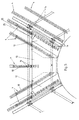
- the basic structure 1 of the work platform shown in FIG. 1 has at the corner points its hexagonal outer contour seen in plan view in its longitudinal direction to the center of the working platform aligned carrier 2, which on Base frame are slidably mounted in the direction of their longitudinal extent.
- On The front free ends of the carrier shoes 3 are set, over which the Working platform can be hung in bracket parts attached to the building wall is.
- These bracket parts can be of conventional, related Climbing formwork used anchors are formed, which are in the building wall encased in concrete, into which so-called climbing cones are screwed are.
- This basic structure is thus via the sliding, slidable carrier 2 to different diameters of round buildings, their outer diameter change over the height of the structure, adaptable.
- This basic framework carries, as will be described in the following, also to different Customizable stage floor diameter of the outer wall 26 of the building.
- the stage floor comprises profile rails fastened to the undersides of the floor panels 4, which are shown in more detail in FIGS. 6 and 7.
- the profile rails 4 comprise a horizontal web 5, on the side extending downwards Sidewalls 6 are arranged, the lower ends of which are angled inwards are and form horizontally extending extensions 7.
- L-shaped fastening webs 8 are defined, which have a vertical, on the outside of the side wall 6 and a horizontal section have outwardly projecting section.
- Sections are holes 9, 10 and 11 for attaching the bottom plates of the Stage floor, the railing post and the support post for the railing intended.
- Rollers 14 are on the upper horizontal for moving the base plates Struts of the basic structure 1 attached, and that is for each Profile rail 4 on a roller 14 on an outer and a roller 14 on an interior of the horizontal struts of the basic structure. How 7, the trolleys have a vertical web 15 a roller 16 is freely rotatably mounted on both sides. A trolley could also have multiple pairs of casters. If the floor slabs 12, 13 assume the outwardly shifted position according to FIG. 3, are the undersides of the horizontal webs 5 of the profile rails 4 on the rollers 16 on. In the course of the inward shift into that shown in Fig. 4 Position occurs in the external trolleys 14, a load change, so that the rollers 16 come to rest on the tops of the extensions 7 and roll on it.
- a railing comprises vertical railing posts 17 (see FIG. 9 and 10). These railing posts 17 are each directly on the rails 4 outside of the outer edge of the base plates 12, 13 by means of Bores 10 in the fastening webs 8 screws. The Railing posts 17 could also be fastened in the edge region of the base plates 12, 13 become.
- Support post 18 In a more distant area that over the outer edges the base plates 12, 13 projecting sections of the rails 4 are further Support post 18 attached. These support posts 18 are inclined to Arranged vertically and support the railing posts against a load towards the free outside of the work platform.
- mounting frames 19 On the railing posts 17 are mounting frames 19 which are circumferentially closed at several heights set which serve to hold handrail strips 20. Although in the Figures 9 and 10 only handrail strips in the area of the top bracket frame 19 are shown, are preferably at all heights of the mounting frame 19 such handrail strips are provided.
- the two side floor panels 12 and the middle floor panel 13 includes, for each height of the support frame 19 two handrail strips 20 provided in the central area of the segment (in the area of the middle railing post 17) depending on the position of the base plates 12, 13 overlap more or less.
- the two handrail strips 20 are each on the Bracket frame 19 of the railing post 17, the 4 on the rails lateral base plates 12 are fixed, rigidly attached.
- the handrail strips 20 In the openings 21 of the Bracket frame 19 of the middle railing post 17 are the handrail strips 20, however, can be moved freely in the longitudinal direction of the handrail strips.
- the railing posts, Support posts and handrail strips are preferably made of aluminum profiles educated.
- the basic structure can the basic structure by removing the inserts 27 in the horizontal struts are reduced. Furthermore, the floor slabs 12, 13 by those with the reduced floor plan of the segment of Stage floor between two beams 2 adapted dimensions, accordingly Fig. 5, exchanged.
- the two side base plates 12 the same attached to the horizontal struts of the basic structure 1 Trolleys used as before.
- For the middle base plate are for this Fall two trolleys on either side of the outer horizontal strut intended.
- the weight of the middle base plate carried by the two side base plates on which this is supported (the rolling devices 14 for the profile rail 4 of the in the figures 3 and 4 shown middle base plate are on the inserts 27th attached and have been removed with these).
- the basic structure can also be constructed in a different form from that shown his.
- tension rods provided along the diagonal of the vertical standing, rectangular elements formed by the struts.
Landscapes
- Engineering & Computer Science (AREA)
- Architecture (AREA)
- Mechanical Engineering (AREA)
- Civil Engineering (AREA)
- Structural Engineering (AREA)
- Bridges Or Land Bridges (AREA)
- Movable Scaffolding (AREA)
Abstract
Description
- Fig. 1
- 1 eine perspektivische Darstellung des Grundgerüstes der Arbeitsbühne;
- Fig. 2
- eine schematische Draufsicht auf einen Teil der Arbeitsbühne, wobei die Bodenplatten des Bühnenbodens weggelassen sind;
- Fig. 3
- eine Fig. 2 entsprechende Ansicht eines Teils der Arbeitsbühne mit den Bodenplatten im vollständig nach außen verschobenen Zustand;
- Fig. 4
- eine Fig. 3 entsprechende Ansicht mit den Bodenplatten in die vollständig nach innen verfahrene Position;
- Fig. 5
- eine den Figuren 2 bis 4 entsprechende Draufsicht, wobei die Zwischenstücke des Grundgerüstes herausgenommen sind und ein entsprechend angepaßter Bühnenboden vorgesehen ist;
- Fig. 6
- eine Draufsicht auf eine Profilschiene;
- Fig. 7
- eine Seitenansicht der Profilschiene von Fig. 6, zusammen mit einem Rollapparat;
- Fig. 8
- eine schematische Seitenansicht der Justiervorrichtung und
- Fig. 9 und Fig. 10
- eine schematische Seitenansicht und eine schematische Vorderansicht eines Geländerpfostens mit Stützpfosten und Abschnitten der obersten Handlaufleisten.
- 1
- Grundgerüst
- 2
- Träger
- 3
- Schuh
- 4
- Profilschiene
- 5
- Horizontalsteg
- 6
- Seitenwange
- 7
- Fortsatz
- 8
- Befestigungssteg
- 9
- Bohrung
- 10
- Bohrung
- 11
- Bohrung
- 12
- seitliche Bodenplatte
- 13
- mittlere Bodenplatte
- 14
- Rollapparat
- 15
- Vertikalsteg
- 16
- Laufrolle
- 17
- Geländerpfosten
- 18
- Abstützpfosten
- 19
- Halterungsrahmen
- 20
- Handlaufleiste
- 21
- Öffnung
- 22
- Gewindestange
- 23
- Winkel
- 24
- Flacheisen
- 25
- Stellmutter
- 26
- Außenwandung
- 27
- Einsatzstück
Claims (11)
- Bei der Errichtung von Gebäuden, insbesondere von Rundbauten mit einer kreisförmigen, sich über die Höhe des Gebäudes in ihrem Durchmesser verändernden Außenkontur, an der Außenseite des Gebäudes einsetzbare Arbeitsbühne, welche ein das Gebäude an seiner Außenseite umgebendes Grundgerüst mit verstellbaren, an den Außendurchmesser des Gebäudes anpaßbaren Trägern, über welche die Arbeitsbühne an der Gebäudewand befestigbar ist, und einen vom Grundgerüst getragenen Bühnenboden, der zumindest eine gegenüber dem Grundgerüst verschiebbare Bodenplatte umfaßt, sowie ein am äußeren Umfang der Arbeitsbühne angebrachtes Geländer aufweist, dadurch gekennzeichnet, daß am Grundgerüst (1) Rollapparate (14) angebracht sind, welche jeweils zumindest ein Laufrollenpaar aufweisen, dessen beide Laufrollen (16) frei drehbar gelagert sind, und daß an den Unterseiten der Bodenplatten (12, 13) des Bühnenbodens Profilschienen (4) befestigt sind, die einen Horizontalsteg und seitlich an diesem angeordnete, abwärts verlaufende Seitenwangen umfassen, deren untere freie Enden nach innen abgewinkelt sind und horizontal nach innen verlaufende Fortsätze (7) bilden, wobei die Profilschienen (4) jeweils zumindest ein Paar von Laufrollen (16) eines Rollapparates (14) aufnehmen und entlang von diesen verschiebbar sind und wobei die Profilschienen (4) auf der von der Außenwandung (26) des Gebäudes abgewandten Außenseite der Arbeitsbühne über den Rand der jeweiligen Bodenplatte (12, 13) vorragen und am vorragenden Abschnitt der Profilschiene (4) ein Abstützpfosten (18) des Geländers befestigt ist.
- Arbeitsbühne nach Anspruch 1, dadurch gekennzeichnet, daß die Arbeitsbühne im Grundriß vier- oder sechseckig ausgebildet ist, wobei an den Eckpunkten horizontal liegende, verschiebbar gelagerte Träger (2) angeordnet sind, deren gedachte Verlängerungen nach innen zum Mittelpunkt der Arbeitsbühne verlaufen.
- Arbeitsbühne nach Anspruch 2, dadurch gekennzeichnet, daß an den vorderen freien Enden der Träger (2) Schuhe (3) zum Einhängen der Arbeitsbühne in an der Gebäudewand angebrachten Halterungsteilen festgelegt sind.
- Arbeitsbühne nach einem der Ansprüche 1 bis 3, dadurch gekennzeichnet, daß im Bereich zwischen zwei horizontal verlaufenden, verschiebbaren Trägern (2) jeweils drei Bodenplatten angeordnet sind, an deren Unterseiten jeweils mindestens eine Profilschiene (4) befestigt ist, die auf den Laufrollen (16) der zugehörigen Rollapparate (14) verschiebbar ist.
- Arbeitsbühne nach Anspruch 4, dadurch gekennzeichnet, daß an den Unterseiten der beiden seitlichen Bodenplatten (12) jeweils zwei in den beiden seitlichen Randbereichen der Bodenplatten (12) angeordnete Profilschienen (4) vorgesehen sind.
- Arbeitsbühne nach Anspruch 5, dadurch gekennzeichnet, daß für die an den seitlichen Bodenplatten (12) angebrachten Profilschienen (4) jeweils ein im inneren Bereich des Grundgerüstes (1) sowie ein im äußeren Bereich des Grundgerüstes (1) angeordneter Rollapparat vorgesehen ist.
- Arbeitsbühne nach einem der Ansprüche 4 bis 6, dadurch gekennzeichnet, daß die Randbereiche der mittleren Bodenplatte (13) auf den äußeren Bodenplatten (12) aufliegen.
- Arbeitsbühne nach einem der Ansprüche 1 bis 7, dadurch gekennzeichnet, daß das Geländer vertikal stehende Geländerpfosten (17) umfaßt, die von den in einer Neigung zur Vertikalen angeordneten Abstützpfosten (18) gegen eine Belastung in Richtung der freien Außenseite der Arbeitsbühne abgestützt werden.
- Arbeitsbühne nach Anspruch 8, dadurch gekennzeichnet, daß eine jeweilige Handlaufleiste (20) des Geländers an einem oder mehreren Geländerpfosten (17), die mit einer Profilschiene (4) einer ersten Bodenplatte verbunden sind, starr befestigt ist und an einem oder mehreren Geländerpfosten (17), welche mit einer Profilschiene (4) einer zweiten, benachbarten Bodenplatte verbunden sind, in Längsrichtung der Handlaufleiste (20) verschiebbar gelagert ist.
- Arbeitsbühne nach einem der Ansprüche 1 bis 9, dadurch gekennzeichnet, daß eine Justiervorrichtung zum Verschieben des Bühnenbodens und zur Fixierung des Bühnenbodens in der eingestellten Position vorgesehen ist, wobei die Justiervorrichtung zumindest eine mit einer Bodenplatte starr verbundene Gewindestange (22) umfaßt, welche durch eine Stellmutter (25) verläuft, die an einem mit dem Grundgerüst verbundenen Teil verdrehbar, aber in Längsrichtung der Gewindestange unverschiebbar gelagert ist.
- Arbeitsbühne nach Anspruch 10, dadurch gekennzeichnet, daß bei einer Verschiebung einer mit einer Gewindespindel starr verbundenen Bodenplatte eine benachbarte Bodenplatte von dieser mit einer Gewindespindel starr verbundenen Bodenplatte über einen oder mehrere Anschläge mitgeführt wird.
Priority Applications (1)
| Application Number | Priority Date | Filing Date | Title |
|---|---|---|---|
| AT01117351T ATE413504T1 (de) | 2000-08-11 | 2001-07-18 | Verstellbare arbeitsbühne |
Applications Claiming Priority (2)
| Application Number | Priority Date | Filing Date | Title |
|---|---|---|---|
| AT0058600U AT4624U1 (de) | 2000-08-11 | 2000-08-11 | Verstellbare arbeitsbühne |
| AT5862000 | 2000-08-11 |
Publications (3)
| Publication Number | Publication Date |
|---|---|
| EP1179647A2 true EP1179647A2 (de) | 2002-02-13 |
| EP1179647A3 EP1179647A3 (de) | 2003-04-23 |
| EP1179647B1 EP1179647B1 (de) | 2008-11-05 |
Family
ID=3494495
Family Applications (1)
| Application Number | Title | Priority Date | Filing Date |
|---|---|---|---|
| EP01117351A Expired - Lifetime EP1179647B1 (de) | 2000-08-11 | 2001-07-18 | Verstellbare Arbeitsbühne |
Country Status (5)
| Country | Link |
|---|---|
| EP (1) | EP1179647B1 (de) |
| AT (2) | AT4624U1 (de) |
| DE (1) | DE50114462D1 (de) |
| DK (1) | DK1179647T3 (de) |
| ES (1) | ES2316411T3 (de) |
Cited By (8)
| Publication number | Priority date | Publication date | Assignee | Title |
|---|---|---|---|---|
| WO2003038277A1 (es) * | 2001-11-02 | 2003-05-08 | Blanca Benedicto Soler | Andamio para aerogeneradores con fuste de sección variable |
| AU2004308998B2 (en) * | 2003-12-30 | 2010-01-28 | Pp Energy Aps | Device for enabling access to a structure above ground level |
| DE102013002886B3 (de) * | 2013-02-19 | 2014-03-27 | Gerhard Lehmann | Vorrichtung zur Befahrung von Türmen und/oder turmartigen Bauwerken, insbesondere von Windkraftanlagen |
| EP2881522A1 (de) * | 2013-12-03 | 2015-06-10 | Francis Dolan | Plattform |
| CN112376889A (zh) * | 2020-11-17 | 2021-02-19 | 浙江铠甲建筑科技有限公司 | 一种便于调节的爬升脚手架顶部防护棚结构 |
| CN115142660A (zh) * | 2022-08-19 | 2022-10-04 | 北京城建北方集团有限公司 | 一种可平行移动的盘扣桁架操作平台及其施工方法 |
| CN115559511A (zh) * | 2022-12-01 | 2023-01-03 | 北京市第三建筑工程有限公司 | 一种高层顶部悬挑结构的滑移围护体系及其抗风压设计方法 |
| CN117513714A (zh) * | 2024-01-04 | 2024-02-06 | 河北盛卓建筑设备制造有限公司 | 一种建筑施工升降平台 |
Families Citing this family (2)
| Publication number | Priority date | Publication date | Assignee | Title |
|---|---|---|---|---|
| CN108547438B (zh) * | 2018-05-07 | 2023-06-02 | 天元建设集团有限公司 | 一种升降式支架及其施工方法 |
| CN117684734A (zh) * | 2023-11-20 | 2024-03-12 | 中建八局第四建设有限公司 | 一种后支腿加高异型吊篮的施工方法 |
Family Cites Families (2)
| Publication number | Priority date | Publication date | Assignee | Title |
|---|---|---|---|---|
| DE3526088A1 (de) * | 1985-07-20 | 1987-01-22 | Michael Barnsteiner | Schutzbuehne fuer schornsteine |
| DE4344210A1 (de) * | 1993-12-23 | 1995-06-29 | Peter Dipl Ing Hausig | Umlaufend hängende Arbeitsbühne für turmartige Bauwerke |
-
2000
- 2000-08-11 AT AT0058600U patent/AT4624U1/de not_active IP Right Cessation
-
2001
- 2001-07-18 DK DK01117351T patent/DK1179647T3/da active
- 2001-07-18 AT AT01117351T patent/ATE413504T1/de active
- 2001-07-18 EP EP01117351A patent/EP1179647B1/de not_active Expired - Lifetime
- 2001-07-18 DE DE50114462T patent/DE50114462D1/de not_active Expired - Lifetime
- 2001-07-18 ES ES01117351T patent/ES2316411T3/es not_active Expired - Lifetime
Cited By (11)
| Publication number | Priority date | Publication date | Assignee | Title |
|---|---|---|---|---|
| WO2003038277A1 (es) * | 2001-11-02 | 2003-05-08 | Blanca Benedicto Soler | Andamio para aerogeneradores con fuste de sección variable |
| AU2004308998B2 (en) * | 2003-12-30 | 2010-01-28 | Pp Energy Aps | Device for enabling access to a structure above ground level |
| US8083029B2 (en) | 2003-12-30 | 2011-12-27 | Pp Energy Aps | Device for enabling access to a structure above ground level |
| DE102013002886B3 (de) * | 2013-02-19 | 2014-03-27 | Gerhard Lehmann | Vorrichtung zur Befahrung von Türmen und/oder turmartigen Bauwerken, insbesondere von Windkraftanlagen |
| EP2881522A1 (de) * | 2013-12-03 | 2015-06-10 | Francis Dolan | Plattform |
| GB2520939B (en) * | 2013-12-03 | 2017-02-08 | Dolan Francis | A Platform |
| CN112376889A (zh) * | 2020-11-17 | 2021-02-19 | 浙江铠甲建筑科技有限公司 | 一种便于调节的爬升脚手架顶部防护棚结构 |
| CN115142660A (zh) * | 2022-08-19 | 2022-10-04 | 北京城建北方集团有限公司 | 一种可平行移动的盘扣桁架操作平台及其施工方法 |
| CN115559511A (zh) * | 2022-12-01 | 2023-01-03 | 北京市第三建筑工程有限公司 | 一种高层顶部悬挑结构的滑移围护体系及其抗风压设计方法 |
| CN117513714A (zh) * | 2024-01-04 | 2024-02-06 | 河北盛卓建筑设备制造有限公司 | 一种建筑施工升降平台 |
| CN117513714B (zh) * | 2024-01-04 | 2024-03-15 | 河北盛卓建筑设备制造有限公司 | 一种建筑施工升降平台 |
Also Published As
| Publication number | Publication date |
|---|---|
| AT4624U1 (de) | 2001-09-25 |
| ES2316411T3 (es) | 2009-04-16 |
| DK1179647T3 (da) | 2009-03-09 |
| EP1179647B1 (de) | 2008-11-05 |
| DE50114462D1 (de) | 2008-12-18 |
| ATE413504T1 (de) | 2008-11-15 |
| EP1179647A3 (de) | 2003-04-23 |
Similar Documents
| Publication | Publication Date | Title |
|---|---|---|
| DE19639038C1 (de) | Kletterschalungssystem und Verfahren zum sukzessiven Betonieren von hohen vertikalen Wänden | |
| EP2052118B1 (de) | Kletterschalung zum betonieren einer wand eines bauwerks | |
| DE2622840A1 (de) | Klettergeruest mit zugehoeriger schalung | |
| EP4248035B1 (de) | Kletterschiene | |
| EP4209656B1 (de) | Modulare tunnelschalungsvorrichtung | |
| EP0851075A1 (de) | Erhöhte Plattform oder Bühne, insbesondere ausgebildet als Deckenschalung für das Betonieren | |
| EP2798133B1 (de) | Paneel für eine system-deckenschalung und system-deckenschalung | |
| EP0930408A1 (de) | Schalung zum Betonieren von auskragenden Betonbauteilen | |
| EP1179647B1 (de) | Verstellbare Arbeitsbühne | |
| AT17062U1 (de) | Fahrbares Arbeitsgerüst | |
| DE1534944A1 (de) | Fuehrung fuer Gleitschalungen | |
| DE102004004883B4 (de) | Deckenschalungs-Paneel und System-Deckenschalung | |
| DE102007021159B4 (de) | Rostdeckenschalung zur Einbindung einer Säule | |
| DE2759088C2 (de) | Klettergerüst mit Kletterschalung zur Herstellung einer Stahlbetonwand | |
| DE19858186A1 (de) | Schalung zum Betonieren von auskragenden Betonbauteilen, insbesondere Kappen, Gesimsen und Überbauten | |
| EP2035314B1 (de) | Hubplattform und verfahren zum aufbauen einer hubplattform | |
| DE1803626A1 (de) | Schalgeruest | |
| DE3836568C2 (de) | Lehrgerüst für Stahlbetonbrücken für universellen Einsatz als stationäres und Verschiebegerüst | |
| DE202017101760U1 (de) | Bausatz für einen temporären Lastenaufzug | |
| DE69000120T2 (de) | Verfahren zum einbau von decken in ein umfangsgeschlossenes bauwerk, dessen betonwandung mit hilfe einer kontinuierlichen kletterschalung errichtet wird | |
| EP0686740B1 (de) | Fahrbares Baugerüst | |
| DE2402683C3 (de) | Kletterschalung | |
| DE3242570C2 (de) | ||
| DE4318012C2 (de) | Einrichtung zum Errichten von Bauwerkswänden | |
| DE10022662C2 (de) | Vorrichtung zum schrittweisen Verfahren einer Schalung an einem Betonbauwerk |
Legal Events
| Date | Code | Title | Description |
|---|---|---|---|
| PUAI | Public reference made under article 153(3) epc to a published international application that has entered the european phase |
Free format text: ORIGINAL CODE: 0009012 |
|
| AK | Designated contracting states |
Kind code of ref document: A2 Designated state(s): AT BE CH CY DE DK ES FI FR GB GR IE IT LI LU MC NL PT SE TR |
|
| AX | Request for extension of the european patent |
Free format text: AL;LT;LV;MK;RO;SI |
|
| PUAL | Search report despatched |
Free format text: ORIGINAL CODE: 0009013 |
|
| AK | Designated contracting states |
Designated state(s): AT BE CH CY DE DK ES FI FR GB GR IE IT LI LU MC NL PT SE TR |
|
| AX | Request for extension of the european patent |
Extension state: AL LT LV MK RO SI |
|
| 17P | Request for examination filed |
Effective date: 20030923 |
|
| AKX | Designation fees paid |
Designated state(s): AT DE DK ES FR GB |
|
| GRAP | Despatch of communication of intention to grant a patent |
Free format text: ORIGINAL CODE: EPIDOSNIGR1 |
|
| RIC1 | Information provided on ipc code assigned before grant |
Ipc: E04G 3/30 20060101ALI20080714BHEP Ipc: E04G 3/24 20060101AFI20080714BHEP |
|
| GRAS | Grant fee paid |
Free format text: ORIGINAL CODE: EPIDOSNIGR3 |
|
| GRAA | (expected) grant |
Free format text: ORIGINAL CODE: 0009210 |
|
| AK | Designated contracting states |
Kind code of ref document: B1 Designated state(s): AT DE DK ES FR GB |
|
| REG | Reference to a national code |
Ref country code: GB Ref legal event code: FG4D Free format text: NOT ENGLISH |
|
| REF | Corresponds to: |
Ref document number: 50114462 Country of ref document: DE Date of ref document: 20081218 Kind code of ref document: P |
|
| REG | Reference to a national code |
Ref country code: DK Ref legal event code: T3 |
|
| REG | Reference to a national code |
Ref country code: ES Ref legal event code: FG2A Ref document number: 2316411 Country of ref document: ES Kind code of ref document: T3 |
|
| PLBE | No opposition filed within time limit |
Free format text: ORIGINAL CODE: 0009261 |
|
| STAA | Information on the status of an ep patent application or granted ep patent |
Free format text: STATUS: NO OPPOSITION FILED WITHIN TIME LIMIT |
|
| 26N | No opposition filed |
Effective date: 20090806 |
|
| REG | Reference to a national code |
Ref country code: DK Ref legal event code: EBP |
|
| GBPC | Gb: european patent ceased through non-payment of renewal fee |
Effective date: 20090718 |
|
| REG | Reference to a national code |
Ref country code: FR Ref legal event code: ST Effective date: 20100331 |
|
| PG25 | Lapsed in a contracting state [announced via postgrant information from national office to epo] |
Ref country code: FR Free format text: LAPSE BECAUSE OF NON-PAYMENT OF DUE FEES Effective date: 20090731 |
|
| PG25 | Lapsed in a contracting state [announced via postgrant information from national office to epo] |
Ref country code: GB Free format text: LAPSE BECAUSE OF NON-PAYMENT OF DUE FEES Effective date: 20090718 |
|
| PG25 | Lapsed in a contracting state [announced via postgrant information from national office to epo] |
Ref country code: DK Free format text: LAPSE BECAUSE OF NON-PAYMENT OF DUE FEES Effective date: 20090731 |
|
| REG | Reference to a national code |
Ref country code: ES Ref legal event code: FD2A Effective date: 20090720 |
|
| PG25 | Lapsed in a contracting state [announced via postgrant information from national office to epo] |
Ref country code: ES Free format text: LAPSE BECAUSE OF NON-PAYMENT OF DUE FEES Effective date: 20090720 |
|
| REG | Reference to a national code |
Ref country code: DE Ref legal event code: R082 Ref document number: 50114462 Country of ref document: DE Representative=s name: VONNEMANN, KLOIBER & KOLLEGEN, DE |
|
| REG | Reference to a national code |
Ref country code: DE Ref legal event code: R082 Ref document number: 50114462 Country of ref document: DE Representative=s name: VONNEMANN, KLOIBER & KOLLEGEN, DE Effective date: 20130708 Ref country code: DE Ref legal event code: R081 Ref document number: 50114462 Country of ref document: DE Owner name: WD BETEILIGUNGS GMBH, AT Free format text: FORMER OWNER: RUND-STAHL-BAU GESELLSCHAFT M.B.H., FUSSACH, AT Effective date: 20130708 Ref country code: DE Ref legal event code: R082 Ref document number: 50114462 Country of ref document: DE Representative=s name: VONNEMANN KLOIBER & KOLLEGEN, DE Effective date: 20130708 |
|
| PGFP | Annual fee paid to national office [announced via postgrant information from national office to epo] |
Ref country code: DE Payment date: 20130924 Year of fee payment: 13 |
|
| REG | Reference to a national code |
Ref country code: AT Ref legal event code: PC Ref document number: 413504 Country of ref document: AT Kind code of ref document: T Owner name: WD BETEILIGUNGS GMBH, AT Effective date: 20131028 |
|
| PGFP | Annual fee paid to national office [announced via postgrant information from national office to epo] |
Ref country code: AT Payment date: 20140714 Year of fee payment: 14 |
|
| REG | Reference to a national code |
Ref country code: DE Ref legal event code: R119 Ref document number: 50114462 Country of ref document: DE |
|
| PG25 | Lapsed in a contracting state [announced via postgrant information from national office to epo] |
Ref country code: DE Free format text: LAPSE BECAUSE OF NON-PAYMENT OF DUE FEES Effective date: 20150203 |
|
| REG | Reference to a national code |
Ref country code: DE Ref legal event code: R119 Ref document number: 50114462 Country of ref document: DE Effective date: 20150203 |
|
| REG | Reference to a national code |
Ref country code: AT Ref legal event code: MM01 Ref document number: 413504 Country of ref document: AT Kind code of ref document: T Effective date: 20150718 |
|
| PG25 | Lapsed in a contracting state [announced via postgrant information from national office to epo] |
Ref country code: AT Free format text: LAPSE BECAUSE OF NON-PAYMENT OF DUE FEES Effective date: 20150718 |