EP1179880A2 - Dynamo-electric machine - Google Patents
Dynamo-electric machine Download PDFInfo
- Publication number
- EP1179880A2 EP1179880A2 EP01101109A EP01101109A EP1179880A2 EP 1179880 A2 EP1179880 A2 EP 1179880A2 EP 01101109 A EP01101109 A EP 01101109A EP 01101109 A EP01101109 A EP 01101109A EP 1179880 A2 EP1179880 A2 EP 1179880A2
- Authority
- EP
- European Patent Office
- Prior art keywords
- winding
- portions
- slots
- windings
- slot
- Prior art date
- Legal status (The legal status is an assumption and is not a legal conclusion. Google has not performed a legal analysis and makes no representation as to the accuracy of the status listed.)
- Granted
Links
Images






Classifications
-
- H—ELECTRICITY
- H02—GENERATION; CONVERSION OR DISTRIBUTION OF ELECTRIC POWER
- H02K—DYNAMO-ELECTRIC MACHINES
- H02K3/00—Details of windings
- H02K3/04—Windings characterised by the conductor shape, form or construction, e.g. with bar conductors
- H02K3/12—Windings characterised by the conductor shape, form or construction, e.g. with bar conductors arranged in slots
-
- H—ELECTRICITY
- H02—GENERATION; CONVERSION OR DISTRIBUTION OF ELECTRIC POWER
- H02K—DYNAMO-ELECTRIC MACHINES
- H02K3/00—Details of windings
- H02K3/04—Windings characterised by the conductor shape, form or construction, e.g. with bar conductors
- H02K3/28—Layout of windings or of connections between windings
-
- H—ELECTRICITY
- H02—GENERATION; CONVERSION OR DISTRIBUTION OF ELECTRIC POWER
- H02K—DYNAMO-ELECTRIC MACHINES
- H02K3/00—Details of windings
- H02K3/46—Fastening of windings on the stator or rotor structure
- H02K3/50—Fastening of winding heads, equalising connectors, or connections thereto
-
- H—ELECTRICITY
- H02—GENERATION; CONVERSION OR DISTRIBUTION OF ELECTRIC POWER
- H02K—DYNAMO-ELECTRIC MACHINES
- H02K11/00—Structural association of dynamo-electric machines with electric components or with devices for shielding, monitoring or protection
- H02K11/04—Structural association of dynamo-electric machines with electric components or with devices for shielding, monitoring or protection for rectification
- H02K11/049—Rectifiers associated with stationary parts, e.g. stator cores
- H02K11/05—Rectifiers associated with casings, enclosures or brackets
-
- H—ELECTRICITY
- H02—GENERATION; CONVERSION OR DISTRIBUTION OF ELECTRIC POWER
- H02K—DYNAMO-ELECTRIC MACHINES
- H02K2203/00—Specific aspects not provided for in the other groups of this subclass relating to the windings
- H02K2203/09—Machines characterised by wiring elements other than wires, e.g. bus rings, for connecting the winding terminations
Definitions
- the present invention relates to armature winding structures of dynamo-electric machines.
- the present invention relates to a stator winding structure of an alternator, for example, an automotive alternator to be mounted on an automotive vehicle, such as an automobile or a truck.
- the outputs of automotive alternators must be increased because of increasing vehicle loads while engine compartments become smaller, thereby reducing spaces for mounting the alternators. Also, there are requirements to reduce the noise of the automotive alternators which operate all the time for supplying electricity, the noise becoming relatively large with respect to the engine noise which has been reduced in response to the requirements to reduce the noise generated toward the outside and the inside of the vehicle compartments.
- the automotive alternators, which operate all the time, are required to have a very high heat resistance because of their severe operating thermal condition in which the alternators are heated by high Joule heat generated by the output current.
- the resistance of a stator winding must be reduced, the space factor of electrical conductors in magnetic circuits of the stator must be increased, and the bridge portions (bridge portions outside a stator core are called coil ends) of the stator winding must be set in order and be concentrated. Furthermore, the requirements for heat resistance, reduced noise, and the like must be complied with.
- the reduction of turns of the stator winding for each phase is effective for reducing the armature raction which causes decrease in the output in a high-rotation range of, for example, 2000 to 5000 rpm.
- the turns can be reduced by reducing the number of electrical conductors received in a slot, by which the flatness ratio (the size of the sections of the conductors in the slot-depth direction divided by the size of the same in the slot-width direction) of the electrical conductors increases.
- the flatness ratio the size of the sections of the conductors in the slot-depth direction divided by the size of the same in the slot-width direction
- a technology is disclosed in, for example, Japanese Unexamined Patent Application Publication No. 2000-92766, in which lap windings (loop windings) and wave windings each constructed by joining short conductor segments are connected in parallel to each other, thereby forming winding phase group for each phase of the stator winding.
- the known stator winding include three types of conductor segments 311, 312, and 313 made of a conductor having a rectangular section and formed substantially in a U-shape.
- Each of the conductor segments 311, 312, and 313 is inserted at the ends thereof in a pair of slots three slots apart (at a magnetic pole pitch) from an end of each slot in the axial direction, and the ends of the conductor segments 311, 312, and 313 extending from the other end of the same slots are connected to each other by welding or the like, thereby forming a coil of windings in four turns around the stator core.
- each slot six conductors are disposed alongside each other in a radial direction of the stator core, the six conductors being two sets of in-slot-received portions 311a, 312a, and 313a of the conductor segments 311, 312, and 313, respectively.
- the positions in each slot which are occupied by the six in-slot-received portions 311a, 312a, and 313a are hereinafter referred to as first address, second address, ..., sixth address from the innermost toward outer positions in a radial direction of the stator core.
- a turn portion 313b of the conductor segment 313 is covered by a turn portion 312b of the conductor segment 312, and the turn portion 312b of the conductor segment 312 is covered by a turn portion 311b of the conductor segment 311, at an axial end face of the stator core.
- an end 313c of the conductor segment 313 extending from the third address of a slot is connected to an end 313c of the other conductor segment 313 extending from the fourth address of another slot three slots apart, thereby forming two winding sub-portions 301 and 303 each constructed with a wave winding, each in one turn per slot.
- An end 311c of the conductor segment 311 extending from the first address of a slot is connected to an end 312c of the conductor segment 312 extending from the second address of another slot three slots apart, and the end 312c of the conductor segment 312 extending from the fifth address of a slot is connected to the end 311c of the conductor segment 311 extending from the sixth address of another slot three slots apart, thereby forming two winding sub-portions 302 and 304 each constructed with a lap winding, each in two turns per slot.
- each of winding phase groups for three phases is formed by connecting in series the two winding sub-portions 301 and 303, and the two winding sub-portions 302 and 304.
- each of winding phase groups for each turn is formed by connecting in series the winding sub-portion 301 and the winding sub-portion 302, and the winding sub-portion 303 and the winding sub-portion 304, and connecting in parallel the series-connected winding sub-portions 301 and 302 and the series-connected winding sub-portions 303 and 304.
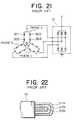
- Three sets of the winding phase groups thus formed are connected into an alternating connection, thereby forming a three-phase alternating winding constituting a stator winding, the stator winding being connected to a rectifier.
- the known stator winding of an automotive alternator are formed in a manner such that three types of the conductor segments 311, 312, and 313 are inserted in a pair of slot separated by a distance of one magnetic-pole pitch from an end of the stator core so that the in-slot-received portions 311a, 312a, and 313a overlap each other, and the ends of the conductor segments 311, 312, and 313 extending from the other end of the stator core are connected to each other.
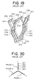
- the height of the coil ends of the stator winding at the end of the stator core 15 is increased, as shown in Fig. 22, whereby a problem has been found in that the alternator including the stator winding cannot be reduced in size, and due to an increased resistance of the stator winding, heat loss becomes large, the heat generation increases at the stator winding, and the leakage reactance at the coil ends increases, whereby the output cannot be increased.
- the turn portion 313b is covered by the turn portion 312b and the turn portion 312b is covered by the turn portion 311b, the exposure area of the coil ends of the stator winding at the end of the stator core 15 is reduced, whereby the stator winding is not efficiently cooled. Therefore, the stator winding is heated up and the output cannot be increased.
- One set of three-phase alternating winding is mounted on the stator core having one slot per phase per pole, and the output thereof is rectified by one rectifier. That is, a small number of the turn portions extending from the slots are disposed in the circumferential direction, whereby the cooling cannot be performed efficiently. Therefore, the stator winding are heated up and the output cannot be increased.
- the heat loss per one rectifying diode increases because only one rectifier is provided, the temperature rises, and an increased output is difficult to obtain.
- a dynamo-electric machine comprises:
- the two series-connected windings may comprise first series-connected winding having n-turns formed by connecting in series the first winding sub-portions disposed in the group of slots and second series-connected winding having n-turns formed by connecting in series the second winding sub-portions disposed in the same group of slots as the group of the slots in which the first winding sub-portions are disposed.
- the strand of wire may be a substantially U-shaped conductor segment, and each of the first winding sub-portion and the second winding sub-portion may include a plurality of the conductor segments forming a wave winding in one turn connected to each other at the open ends thereof.
- the strand of wire may be a continuous conductive wire, and each of the first winding sub-portion and the second winding sub-portion may include a single continuous conductive wire forming a wave winding in one turn.
- Each pair of the first wave-shaped windings and the second wave-shaped windings may be formed with individual wire assemblies including a plurality of the first winding sub-portions and a plurality of the second winding sub-portions.
- the strand of wire may be a conductor having a substantially circular cross-section.
- the two series-connected windings for each phase forming the armature winding may be connected to each other via a metallic terminal.
- the armature core may be a cylindrical stator core made of a laminated iron core, further the dynamo-electric machine may comprise a rotor forming N and S poles along the rotational periphery thereof, the rotor being disposed at an inside of and coaxially with the stator core, and a fan unit fixed to the rotor at the axial ends thereof for applying cooling air to coil-end groups of the armature winding by the rotation of the fan unit.
- the n-pairs of the first wave-shaped windings and the second wave-shaped windings may include protrusions thereof from the axial ends of the stator core decreasing gradually toward the outside in the radial directions of the stator core.
- a dynamo-electric machine comprises:
- each coil end being formed by connecting the in-slot-received portion in the first slots to the other in-slot-received portion occupying addresses, in the slots individually separated from the first slot by the predetermined number of slots, differing in the slot-depth direction from that which is occupied by the in-slot-received portion in the first slot, may be formed at at least one of the axial ends of the armature core, and the protrusion, in the axial direction, of the n-rows of the coil ends may be decreases gradually toward the outside in the radial direction of the armature core.
- each coil end being formed by connecting the in-slot-received portion in the first slots to the other in-slot-received portion occupying addresses, in the slots individually separated from the first slot by the predetermined number of slots, differing in the slot-depth direction from that which is occupied by the in-slot-received portion in the first slot, may be formed at at least one of the axial ends of the armature core, and the coil ends in the n-rows may be arranged substantially evenly in the circumferential direction of the armature core.
- Coil ends each being formed by connecting the in-slot-received portion in the first slots to the other in-slot-received portion occupying addresses, in the slots individually separated from the first slot by the predetermined number of slots, differing in the slot-depth direction from that which is occupied by the in-slot-received portion in the first slot, may be stacked up in n-layers in the axial direction of the armature core at at least one of the axial ends of the armature core, and the coil ends in the n-layers may be arranged substantially evenly in the circumferential direction of the armature core.
- Each strand of wire may be formed with substantially U-shaped conductor segments.
- Each strand of wire may be formed with a continuous conductive wire.
- An insulating resin may be disposed at at least one of the axial ends of the armature core and between the two windings each having n-turns forming the winding phase groups for each phase.
- Fig. 1 is a sectional view of an automotive alternator according to a first embodiment of the present invention.
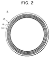
- Figs. 2 and 3 are an end view and a perspective view, respectively, of a stator of the automotive alternator according to the first embodiment of the present invention.
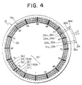
- Fig. 4 is an end view from the rear side of a stator winding of the automotive alternator according to the first embodiment of the present invention, showing the connections for one phase.
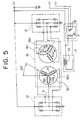
- Fig. 5 is a block diagram of a circuit of the automotive alternator according to the first embodiment of the present invention.
- Fig. 6 is a perspective view of the stator of the automotive alternator according to the first embodiment of the present invention, on which metallic terminals are mounted.
- Fig. 1 is a sectional view of an automotive alternator according to a first embodiment of the present invention.
- Figs. 2 and 3 are an end view and a perspective view, respectively, of a stator of the automotive alternator according to the first embodiment of the present invention.
- Fig. 4 is
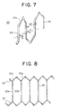
- FIG. 7 is a perspective view of a critical portion of a strand of wire forming the stator winding used in the automotive alternator according to the first embodiment of the present invention.
- Fig. 8 is an illustration of the disposition of the strands of wire forming the stator winding used in the automotive alternator according to the first embodiment of the present invention.
- Figs. 9A and 9B are an end view and a plan view, respectively, of a winding assembly forming the stator winding used in the automotive alternator according to the first embodiment of the present invention.
- lead wires and the like are omitted.
- wires at the rear side are shown by continuous lines and wires at the front side are shown by dotted lines.
- the automotive alternator shown in Fig. 1 includes a Lundell-type rotor 7 rotatably supported by a shaft 6 in a case 3 formed with aluminum front bracket 1 and rear bracket 2.
- a stator 8 serving as an armature is fixed to the inner wall of the case 3 so as to cover the rotor 7 serving as a field at the periphery of the rotor 7.
- the shaft 6 is rotatably supported by the front bracket 1 and the rear bracket 2.
- a pulley 4 is fixed to the shaft 6 at one end thereof, for transmitting the rotational torque of an engine to the shaft 6 via a belt (not shown).
- Slip rings 9 for feeding current are fixed to the other end of the shaft 6.
- a pair of brushes 10 are received in a brush holder 11 disposed in the case 3.
- the pair of brushes 10 are held in contact with the slip rings 9 so as to slide thereon.
- a regulator 18 for regulating alternating voltage generated at the stator 8 is connected to a heat sink 17 coupled with the brush holder 11.
- Rectifiers 12 for rectifying alternating current generated at the stator 8 into direct current are mounted in the case 3, the rectifiers 12 being electrically connected to the stator 8.
- the rotor 7 includes a rotor coil 13 for generating magnetic flux on passage of electric current, and a pair of pole cores 20 and 21 disposed so as to cover the rotor coil 13, magnetic poles being formed in the pole cores 20 and 21 by the magnetic flux generated in the rotor coil 13.
- the pair of iron pole cores 20 and 21 include eight claw-shaped magnetic poles 22 and eight claw-shaped magnetic poles 23 around the peripheries of the pole cores 20 and 21, respectively, protruding therefrom and disposed at the same angular distance from each other in the circumferential directions of the respective pole cores 20 and 21.
- the pair of pole cores 20 and 21 are fastened to the shaft 6 facing each other such that the claw-shaped magnetic poles 22 and 23 intermesh.
- a fan unit 5 is fixed to the rotor 7 at the axial ends thereof.
- Intake openings 1a and 2a are formed in the front bracket 1 and the rear bracket 2, respectively, at each axial end face.
- Discharge openings 1b and two outlets 2b are formed in two outer circumferential shoulder portions of the front bracket 1 and the rear bracket 2, opposite the radial outside of the front-end and rear-end coil-end groups 16f and 16r of a stator winding 16, the coil-end groups 16f and 16r being disposed at the front side and the rear side, respectively, of the stator winding 16.
- the stator 8 includes a cylindrical stator core 15, made of laminated iron, provided with a plurality of slots 15a formed extending in the axial direction at a predetermined pitch in the circumferential direction, the stator winding 16 mounted on the stator core 15, and insulators 19 disposed in the slots 15a for electrically insulating the stator winding 16 from the stator core 15.
- the stator winding 16 includes a plurality of winding sub-portions in each which one strand of wire 30 is bent back outside the slots 15a at end surfaces of the stator core 15 and wound in a wave-shape so as to alternately occupy an inner layer and an outer layer in a slot-depth direction within slots 15a at intervals of a predetermined number of slots (the interval equals a magnetic pole pitch).
- the stator core 15 is provided with ninety-six slots 15a at the same distance from each other so as to receive two sets of a three-phase alternating winding corresponding to the number of the magnetic poles which is 16. That is, two slots per pole per phase make the total number of slots of 96.
- a long copper wire having a rectangular cross-section and coated with an insulating film 49 is used as the strand of wire 30.
- the winding phase group 161 for each phase include first to sixth winding sub-portions 31 to 36, each winding sub-portion being formed with one strand of wire 30.
- the first winding sub-portion 31 is formed in a manner such that one strand of wire 30 is wound in a wave-shape into every sixth slots from slot number 1 to 91 so as to alternately occupy a first position from an inner circumferential side (hereinafter, referred to as a first address) and a second position from the inner circumferential side (hereinafter, referred to as a second address) inside the slots 15a, and the both ends of the strand of wire 30 are connected to each other, thereby forming the wave-shaped winding sub-portion in one turn.
- a first address an inner circumferential side
- a second address from the inner circumferential side
- the second winding sub-portion 32 is formed in a manner such that one strand of wire 30 is wound in a wave-shape into every sixth slots from slot number 1 to 91 so as to alternately occupy the second address and the first address inside the slots 15a, and the both ends of the strand of wire 30 are connected to each other, thereby forming the wave-shaped winding sub-portion in one turn.
- the third winding sub-portion 33 is formed in a manner such that one strand of wire 30 is wound in a wave-shape into every sixth slots from slot number 1 to 91 so as to alternately occupy a third position from an inner circumferential side (hereinafter, referred to as a third address) and a fourth position from the inner circumferential side (hereinafter, referred to as a fourth address) inside the slots 15a, and the both ends of the strand of wire 30 are connected to each other, thereby forming the wave-shaped winding sub-portion in one turn.
- a third address an inner circumferential side
- a fourth position from the inner circumferential side hereinafter, referred to as a fourth address
- the fourth winding sub-portion 34 is formed in a manner such that one strand of wire 30 is wound in a wave-shape into every sixth slots from slot number 1 to 91 so as to alternately occupy the fourth address and the third address inside the slots 15a, and the both ends of the strand of wire 30 are connected to each other, thereby forming the wave-shaped winding sub-portion in one turn.
- the fifth winding sub-portion 35 is formed in a manner such that one strand of wire 30 is wound in a wave-shape into every sixth slots from slot number 1 to 91 so as to alternately occupy a fifth position from an inner circumferential side (hereinafter, referred to as a fifth address) and a sixth position from the inner circumferential side (hereinafter, referred to as a sixth address) inside the slots 15a, and the both ends of the strand of wire 30 are connected to each other, thereby forming the wave-shaped winding sub-portion in one turn.
- a fifth address an inner circumferential side
- a sixth position from the inner circumferential side hereinafter, referred to as a sixth address
- the sixth winding sub-portion 36 is formed in a manner such that one strand of wire 30 is wound in a wave-shape into every sixth slots from slot number 1 to 91 so as to alternately occupy the sixth address and the fifth address inside the slots 15a, and the both ends of the strand of wire 30 are connected to each other, thereby forming the wave-shaped winding sub-portion in one turn.
- the strands of wire 30 are arranged to line up a row of six strands within each slots 15a with the longitudinal direction of their rectangular cross sections aligned in a redial direction.
- Portions of the strands of wire 30 of the second, fourth, and sixth winding sub-portions 32, 34, and 36 extending from slot numbers 61 and 67 at an end face of the stator core 15 are cut, and portions of the strands of wire 30 of the first, third, and fifth winding sub-portions 31, 33, and 35 extending from slot numbers 67 and 73 at the end face of the stator core 15 are cut. Then, a cut end 31a of the first winding sub-portion 31 and a cut end 33b of the third winding sub-portion 33 are connected. A cut end 33a of the third winding sub-portion 33 and a cut end 35b of the fifth winding sub-portion are connected.
- a first series-connected winding 162a in three turns are formed with the first, third, and fifth winding sub-portions 31, 33, and 35 connected to each other in series.
- a cut end 32a of the second winding sub-portion 32 and a cut end 34b of the fourth winding sub-portion 34 are connected.
- a cut end 34a of the fourth winding sub-portion 34 and a cut end 36b of the sixth winding sub-portion are connected.
- a second series-connected winding 162b in three turns are formed with the second, fourth, and sixth winding sub-portions 32, 34, and 36 connected to each other in series.
- the connected portion of the cut ends 31b and 36a of the first and sixth winding sub-portions 31 and 36 serves as a neutral point N.
- the connected portion of the cut ends 32b and 35a of the second and fifth winding sub-portions 32 and 35 serves as a lead wire O.
- Each strand of wire 30 constituting the first to sixth winding sub-portions 31 to 36 is wound in a wave-shape in a manner such that the strand of wire 30 extends from one of the slots 15a at an end face of the stator core 15, is folded back outside the slots 15a and is inserted in another slot 15a disposed away across five slots 15a therebetween.
- Each strand of wire 30 is wound so as to occupy alternately the inner layer and the outer layer with respect to the slot-depth direction (radial direction) in every sixth slot.
- the strand of wire 30 extend outwards from each of the slots 15a at the end faces of the stator core 15 and is folded back to form turn portions 30a served as coil ends.
- the turn portions 30a which are formed into substantially the same shape at both ends of the stator 15 are mutually spaced circumferentially and radially, and arranged neatly in three rows circumferentially, to form coil-end groups 16f and 16r.
- a metallic terminal 50 includes a phase-a lead wire 51a, a phase-b lead wire 51b, a phase-c lead wire 51c, and a neutral-point lead wire 52 are formed integrally with each other via an insulative resin 53.
- the phase-a lead wire 51a includes connection tabs 51a 1 and 51a 2 formed integrally therewith.
- the phase-b lead wire 51b includes connection tabs 51b 1 and 51b 2 formed integrally therewith.
- the phase-c lead wire 51c includes connection tabs 51c 1 and 51c 2 formed integrally therewith.
- the neutral-point lead wire 52 includes connection tabs 52a 1 , 52a 2 , 52b 1 , 52b 2 , 52c 1 , and 52c 2 formed integrally therewith.
- the fifth and second winding sub-portions 35 and 32 constituting the winding phase group 161 for phase a are welded to the connection tabs 51a 1 and 51a 2 , respectively, at the cut ends 35a and 32b, respectively.
- the first and sixth winding sub-portions 31 and 36 constituting the winding phase group 161 for phase a are welded to the connection tabs 52a 1 and 52a 2 , respectively, at the cut ends 31b and 36a, respectively.
- the fifth and second winding sub-portions 35 and 32 constituting the winding phase group 161 for phase b are welded to the connection tabs 51b 1 and 51b 2 , respectively, at the cut ends 35a and 32b, respectively.
- the first and sixth winding sub-portions 31 and 36 constituting the winding phase group 161 for phase b are welded to the connection tabs 52b 1 and 52b 2 , respectively, at the cut ends 31b and 36a, respectively.
- the fifth and second winding sub-portions 35 and 32 constituting the winding phase group 161 for phase c are welded to the connection tabs 51c 1 and 51c 2 , respectively, at the cut ends 35a and 32b, respectively.
- the first and sixth winding sub-portions 31 and 36 constituting the winding phase group 161 for phase c are welded to the connection tabs 52c 1 and 52c 2 , respectively, at the cut ends 31b and 36a, respectively.
- the winding phase groups 161 for each phase are formed by connecting in parallel the first series-connected windings 162a including the first, third, and fifth winding sub-portions 31, 33, and 35 connected in series and the second series-connected windings 162b including the second, fourth, and sixth winding sub-portions 32, 34, and 36 connected in series.
- Each neutral point of the winding phase groups 161 for each phase is connected to the neutral-point lead wire 52, and three sets of winding phase group 161 are connected into an alternating connection (into a star connection), thereby forming the three-phase alternating winding 160.
- phase-a lead wire 51a, the phase-b lead wire 51b, the phase-c lead wire 51c, and the neutral-point lead wire 52 of each metallic terminal 50 are connected to the rectifier 12, whereby the configuration of a circuit shown in Fig. 5 is obtained.
- Each of the first to sixth winding sub-portions 31 to 36 is constructed by winding the strand of wire 30 in a wave-shape so as to occupy alternately the inner layer and the outer layer in the slot-depth direction in every sixth slot 15a.
- the second, fourth, and sixth winding sub-portions 32, 34, and 36 are inversely wound and offset by an electrical angle of 180 degrees relative to the first, third, and fifth winding sub-portions 31, 33, and 35, respectively.
- the stator winding 16 thus formed has the same configuration as that in which three pairs of first wave-shaped winding groups constructed with the first winding sub-portions 31 and second wave-shaped winding groups constructed with the second winding sub-portions 32 are disposed so as to stack up in the radial direction of the stator core 15, each pair forming coaxial circles having different radius from each other around the stator core 15.
- Each pair of the first wave-shaped winding groups and the second wave-shaped winding groups are formed with a winding assembly constructed by knitting together twelve conductive wires 30 in a wave-shape.
- Fig. 7 is a perspective view of a critical portion of a strand of wire forming the stator winding used in the automotive alternator.
- Fig. 8 is an illustration of the disposition of the strands of wire forming the stator winding used in the automotive alternator.
- Fig. 9A is an end view of the winding assembly forming the stator winding used in the automotive alternator, and Fig. 9B is a plan view of the same.
- the strand of wire 30 is made of a continuous copper wire having a rectangular section and coated with an insulative film 49.
- the strand of wire 30, as shown in Fig. 7, is formed by bending it into a planar pattern in which straight portions 30b as in-slot-received portions connected by turn portions 30a are lined up at a pitch of six slots (6p). Adjacent straight portions 30b are offset alternately by a distance equal to one width (w) of the strands of wire 30 by means of the turn portions 30a.
- Fig. 8 two strands of wire 30 formed in such a pattern are overlapped the straight portions 30b each other by being offset by a pitch of six slots, thereby forming a wire-strand pair.
- the wire-strand pair corresponds to a pair of the first and second winding sub-portions 31 and 32.
- a winding assembly 39 shown in Figs. 9A and 9B is constructed by arranging six wire-strand pair so as to be offset by a pitch of one slot from each other. Six ends of the strands of wire 30 extend at each side of each end of the winding assembly 39. The turn portions 30a are arranged so as to line up in rows on the sides of the winding assembly 39.
- Three winding assemblies 39 thus arranged are mounted so as to stack up within slots 15a of a stator core 15, thereby forming a stator before wire-connection.
- the ends of the strands of wire 30 are connected on the basis of the connecting method shown in Fig. 4 to obtain the stator winding 16.
- the fan unit 5 applies external air to a heat sink of the rectifiers 12 and the heat sink 17 of the regulator 18 through the intake openings 2a disposed opposing to the heat sink of the rectifiers 12 and the heat sink 17, respectively, whereby the air flows along the shaft 6 and cools the rectifiers 12 and the regulator 18. Thereafter, the air path is bent toward the outside in the radial directions by the fan unit 5, and the air cools the coil-end group 16r at the rear side of the stator winding 16 and is discharged through the discharge openings 2b.
- the fan unit 5 draws the external air along the shaft 6 through the intake openings 1a. Then, the air path is bent toward the outside in the radial directions by the fan unit 5, and the air cools the coil-end group 16f at the front side of the stator winding 16 and is discharged through the discharge openings 1b.
- the stator winding 16 includes two three-phase alternating windings 160, each of the three-phase alternating windings 160 including three winding phase groups 161 connected into an alternating connection.
- Each set of the winding phase group 161 includes the first to sixth winding sub-portions 31 to 36.
- the strand of wire 30 forming the first winding sub-portion 31 is wound in one turn in a wave-shape so as to occupy alternately the first address and the second address in every sixth slot 15a. That is, the first winding sub-portion 31 includes the strand of wire 30 wound in one turn in a wave-shape so as to occupy alternately the inner layer and the outer layer in the slot-depth direction in one slot 15a at intervals of six slots.
- the second winding sub-portion 32 includes the strand of wire 30 wound in one turn in a wave-shape so as to occupy alternately the inner layer and the outer layer in the slot-depth direction in every sixth slot 15a, the second winding sub-portion 32 being inversely wound and offset by an electrical angle of 180 degrees relative to the first winding sub-portion 31.
- the third winding sub-portion 33 includes the strand of wire 30 wound in one turn in a wave-shape so as to occupy alternately the third address and the fourth address in the slot-depth direction in every sixth slot 15a.
- the fourth winding sub-portion 34 includes the strand of wire 30 wound in one turn in a wave-shape so as to occupy alternately the fourth address and the third address in the slot-depth direction in every sixth slot 15a.
- the fifth winding sub-portion 35 includes the strand of wire 30 wound in one turn in a wave-shape so as to occupy alternately the fifth address and the sixth address in the slot-depth direction in every sixth slot 15a.
- the sixth winding sub-portion 36 includes the strand of wire 30 wound in one turn in a wave-shape so as to occupy alternately the sixth address and the fifth address in the slot-depth direction in every sixth slot 15a.
- Each of the winding phase groups 161 is formed by connecting in parallel the first series-connected winding 162a including the first, third, and fifth winding sub-portions 31, 33, and 35 connected in series and the second series-connected winding 162b including the second, fourth, and sixth winding sub-portions 32, 34, and 36 connected in series.
- stator winding 16 is formed only with wave windings, the height of the coil ends can be reduced and the exposure area of the coil ends can be increased compared with a known technology in which the combination of lap windings and wave windings is used.
- stator an alternator
- the size of a stator can be reduced because the height of coil ends is reduced.
- An increased output can be obtained because the resistance of windings, the heat loss, the heat generation in the stator winding 16, and the leakage reactance in the coil ends are reduced.
- the stator winding 16 can be cooled efficiently due to the enlarged exposure area of the coil ends, whereby the temperature rise in the stator winding 16 can be suppressed, thereby providing a high output of an alternator.
- the winding phase group 161 in three turns can be formed with six winding sub-portions, each being wound in a wave-shape in one turn. That is, the winding phase group 161 in an odd number of turns can be formed by using 2m+1 pairs (m represents a natural number) of winding sub-portions wound in a wave-shape.
- m represents a natural number
- the winding phase group 161 for each phase in an odd number of turns cannot be formed because the winding phase group is constructed by connecting the winding sub-portions in series.
- the winding phase group 161 for each phase in an odd number of turns can be realized by connecting each halved winding sub-portions in series to form two series-connected windings and connecting the two series-connected windings in parallel.
- the flatness ratio of the strand of wire can be reduced even when the number of turns is reduced, the strand of wire can be formed easily.
- a sufficient output cannot be obtained due to the armature reaction in a high rotation range
- reduction of turns of the winding phase group 161 may be a countermeasure.
- a problem may occur in that a sufficient output cannot be obtained in a low rotation range due to an excessively reduced turns in which the winding phase groups are provided in units of two when the winding phase group in an odd number of turns is not available.
- an advantage of the winding phase group in an odd number of turns is that a problem of insufficient output in a high rotation range due to the armature reaction can be solved while maintaining the output in a low rotation range on a permissible level by reducing by one turn for each phase of the stator winding, and the output in a high rotation range can be increased.
- each of the first series-connected windings 162a is composed of the first, third, and fifth winding sub-portions 31, 33, and 35
- each of the second series-connected windings 162b is composed of the second, fourth, and sixth winding sub-portions 32, 34, and 36
- the first and second series-connected windings 162a and 162b are constructed with an inner layer winding, an intermediate layer winding and an outer layer winding in the radial direction of the stator, respectively. Consequently, the first and second series-connected windings 162a and 162b are evenly cooled by cooling air passing through the coil-end groups, thereby suppressing temperature rise in the stator winding.
- the strand of wire 30 is a continuous wire, the number of welding points is significantly reduced, compared with a known technology in which a plurality of conductor segments are used as a strand of wire. Therefore, laborious welding operations can be alleviated, and the efficiency in the operations can be improved, whereby welding quality and yield ratio are improved.
- the coil ends are formed with the turn portions 30a of the strands of wire 30 which are continuous, whereby welding is not necessary for forming the coil ends, thereby reducing the height of the coil-end groups.
- the pairs of the wave windings form the winding assembly 39, whereby the winding operation of the stator winding is simplified, thereby improving efficiency in the manufacture of the stator.
- the turns can be increased simply by mounting a plurality of the winding assemblies 39 overlapping each other on the stator core. When U-shaped conductor segments are mounted, the conductor segments move by the length of each slot or more in the corresponding slots because the conductor segments must be inserted in the slots from an end of a stator core in the longitudinal direction of the conductor segments.
- the winding assembly 39 is inserted into the slots from, for example, the inner periphery of the stator core in a direction perpendicular to the strands of wire, whereby the winding assembly 39 does not move more than the depth of each slot in the corresponding slots. Therefore, there is a reduced risk of damages to the insulative films due to the friction between the strands of wire and the inner walls of the slots, thereby ensuring superior insulation.
- the stator winding can be formed so as to have winding phase groups each having three turns or those each having six turns by using one type of winding configuration and by modifying the metallic terminal 50.
- the modification of the metallic terminal 50 is such that the connection tabs 51a 1 and 51a 2 are separated from the phase-a lead wire 51a and are formed integrally with each other, and the connection tab 52a 2 is separated from the neutral-point lead wire 52 and is formed integrally with the phase-a lead wire 51a.
- connection tabs 51b 1 and 51b 2 are separated from the phase-b lead wire 51b and are formed integrally with each other, and the connection tab 52b 2 is separated from the neutral-point lead wire 52 and is formed integrally with the phase-b lead wire 51b.
- connection tabs 51c 1 and 51c 2 are separated from the phase-c lead wire 51c and are formed integrally with each other, and the connection tab 52c 2 is separated from the neutral-point lead wire 52 and is formed integrally with the phase-c lead wire 51c, Consequently, the first to sixth winding sub-portions 31 to 36 are connected in series to form winding phase groups each having six turns.
- the turn portions 30a of the strands of wire 30 are mutually spaced circumferentially and radially, and arranged neatly in three rows circumferentially, to form coil-end groups 16f and 16r, whereby the protrusions of the coil-end groups 16f and 16r from the ends of the stator core 15 are reduced. Therefore, wind noise due to the rotation of the rotor 7 is reduced, and the leakage reactance at the coil ends decreases, thereby improving the output and the efficiency.
- the turn portions 30a of the strands of wire 30 are mutually spaced circumferentially and radially, and arranged neatly in three rows circumferentially, to form coil-end groups 16f and 16r. Therefore, the wind resistance against the cooling air is even in the circumferential direction, whereby the coil-end groups 16f and 16r are cooled evenly in the circumferential direction, thereby suppressing temperature rise in the stator winding 16.
- Cooling air is applied to the coil-end groups 16f and 16r by the fan unit 5 fixed to the axial ends of the rotor 7, thereby efficiently suppressing temperature rise in the stator winding 16.
- Each of the first and second series-connected windings 162a and 162b is composed of three winding sub-portions which occupy the inner, intermediate, and outer layers, respectively. Therefore, the variations in resistance and inductance among the three winding assemblies 39 produced in the manufacture are distributed evenly between the first and second series-connected windings 162a and 162b, whereby the differences in the resistance and the inductance between the first and second series-connected windings 162a and 162b are reduced.
- the flow of a part of the electrical current through the first series-connected windings 162a into the second series-connected windings 162b can be suppressed, whereby reduction of the output due to circulating currents flowing from the first series-connected windings 162a to the second series-connected windings 162b can be suppressed.
- the stator winding 16 includes two sets of the three-phase alternating winding 160, each including the winding phase groups 161 for three phases connected into a star connection.
- the turn portions 30a extending from ninety-six slots (2 slots per pole per phase) are arranged neatly in rows in the circumferential direction.
- the two sets of the three-phase alternating winding 160 are connected to the individual rectifiers 12.
- the direct outputs of the rectifiers 12 are connected in parallel and are combined with each other.
- Each of the coil-end groups 16f and 16r is formed with three sets of the ninety-six turn portions 30a, each set arranged neatly in a row in the circumferential direction and forming a circle having a radius differing from the others.
- Each of the coil-end groups 16f and 16r including the 288 turn portions 30a is cooled efficiently, thereby suppressing temperature rise in the stator winding and providing an increased output. Since electrical current having phases differing by 30 degrees from each other is generated, the temperature in the coil-end groups is distributed more evenly than in a case of a known alternator, whereby temperature rise in the stator winding is suppressed, and an increased output is provided. Since two sets of rectifiers are used, the loss per one rectifying diode is reduced by half with respect to a known technology, whereby the temperature in the rectifying diodes is reduced, and a higher output is provided.
- harmonic magnetomotive force components which cause magnetic noise of an alternator, can be cancelled.
- the strength of the coil-end groups is increased by disposing the turn portions 30a in three rows alongside in the radial direction, thereby further reducing the magnetic noise.
- substantially U-shaped conductor segments are used instead of the continuous wire used in the first embodiment described above.
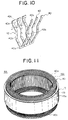
- Fig. 10 is a perspective view showing the disposition of strands of wire 40 forming a stator winding used in an automotive alternator according to the second embodiment.
- Fig. 11 is a perspective view of a stator of the automotive alternator according to the second embodiment. In Fig. 11, lead wires and the like are omitted.
- a short copper wire having a rectangular section coated with an insulative film 49 is used as a strand of wire 40, which includes a pair of straight portions 40b as in-slot-received portions connected by a V-shaped turn portion 40a so as to be formed substantially in a U-shape.
- Three strands of wires 40 are inserted in two slots 15a six slots apart (at a magnetic pole pitch) at the two ends of each strand of wire 40, respectively, from an axial end of a stator core 15.
- the strands of wire 40 are bent at the ends thereof protruding from the other axial end of the stator core 15 so that the ends of each strand of wire 40 separate from each other.
- one of the three strands of wire 40 is inserted at one end thereof in the first address of one of the two slots 15a (a first slot 15a) and at the other end of the strand of wire 40 in the second address of the other one of the two slots 15a (a second slot 15a).
- Another strand of wire 40 is inserted at one end thereof in the third address of the first slot 15a and at the other end of the strand of wire 40 in the fourth address of the second slot 15a.
- the remaining strand of wire 40 is inserted at one end thereof in the fifth address of the first slot 15a and at the other end of the strand of wire 40 in the sixth address of the second slot 15a.
- other sets of the three strands of wire 40 are inserted in every slot 15a at the magnetic pole pitch so that six straight portions 40b of the strands of wire 40 are disposed alongside each other in the radial direction in each slot 15a.
- the strands of wire 40 are connected to each other at an end 40c of each strand of wire 40 protruding from the first address of the slot 15a with the end 40c of each of the other strand of wires 40 protruding from the second address of the slot 15a separated from the former slot 15a with five slots therebetween, whereby two wave windings, each in one turn, are obtained. These two wave windings correspond to the first and second winding sub-portions 31 and 32.
- the strands of wire 40 are connected to each other at the end 40c of each strand of wire 40 protruding from the third address of the slot 15a with the end 40c of each of the other strands of wire 40 protruding from the fourth address of the slot 15a separated from the former slot 15a with five slots therebetween, whereby two wave windings, each in one turn, are obtained. These two wave windings correspond to the third and fourth winding sub-portions 33 and 34.
- the strands of wire 40 are connected to each other at the end 40c of each strand of wire 40 protruding from the fifth address of the slot 15a with the end 40c of each of the other strands of wire 40 protruding from the sixth address of the slot 15a separated from the former slot 15a with five slots therebetween, whereby two wave windings, each in one turn, are obtained. These two wave windings correspond to the fifth and sixth winding sub-portions 35 and 36.
- stator 8a shown in Fig. 11 is obtained, which is formed with a stator winding 16A including the wave windings, each in one turn, mounted on the stator core 15.
- a coil-end group is formed with the turn portions 40a lined up in a row in the radial direction of the stator core 15, whereby the protrusion of the coil-end group can be reduced, and the exposure area increases, compared with the known technology in which the turn portions 311a, 312a, and 313a forming the coil-end group stack up in three layers in the axial direction of the stator core. Therefore, the size of an alternator can be reduced, and an increased output can be obtained of the alternator.
- a continuous copper wire having a circular cross-section coated with an insulating film 49 is used as a strand of wire 45.
- the strand of wire 45 as shown in Fig. 12, is formed by bending it into a planar pattern in which straight portions 45b served as in-slot-received portions connected by turn portions 45a are lined up at a pitch of six slots (6p). Adjacent straight portions 45b are offset alternately by a distance equal to one width (w) of the strands of wire 45 by means of the turn portions 45a.
- the other configuration of the wire 45 is the same as that of the wire 30 described in the first embodiment.
- the strand of wire 45 has a circular cross-section, according to the third embodiment, bending operations can be performed more easily than that of the strand of wire 30 which has a rectangular cross-section.
- the turn portions 45a (coil-end portion) can be easily formed, whereby a winding assembly 39 can be easily manufactured.
- the strand of wire 30 having a rectangular cross-section When the strand of wire 30 having a rectangular cross-section is used, there is a risk of damaging the insulating film 49 due to the edge of the strand of wire 30 during the forming of the winding assembly 39 and the mounting thereof on the stator core 15.
- the strand of wire 45 since the strand of wire 45 has a circular cross-section, the damage to the insulating film 49 due to the interference between the strands of wire can be suppressed, thereby improving insulation reliability.
- the strand of wire 30 used in the first embodiment is replaced by a continuous copper wire having a circular cross-section
- the strand of wire 40 according to the second embodiment may be replaced by conductor segments having a circular cross-section.
- a winding assembly 39 includes turn portions 30a disposed in three rows around the periphery of the stator core, of which the protrusion in the axial direction is reduced gradually toward the outside in the radial directions of the stator core, as shown in Fig. 13.
- the other configuration is the same as that which is described in the first embodiment.
- the turn portions 30a included in the winding assembly 39 are disposed in three rows around the periphery of the stator core, the protrusion of each row in the axial direction is the same as that of the other rows. Therefore, the resistances of the first to sixth winding sub-portions 31 to 36 are substantially the same as each other, whereby the generated heat is substantially the same between each winding sub-portion.
- the first to sixth winding sub-portions 31 to 36 are more likely to be cooled by cooling air at the inner part. Therefore, the temperature is more likely to increase at the outer side of stator winding 16, whereby the stator winding 16 cannot be cooled efficiently.
- the winding assembly 39 includes the turn portions 30a disposed in three rows around the periphery of the stator core, of which the protrusion in the axial direction is reduced gradually toward the outside in the radial directions of the stator core. Therefore, the resistance of the first to sixth winding sub-portions 31 to 36 is lower toward the outside in the radial directions, and the generated heat increases toward the inside in the radial directions.
- the windings heated up more, which are disposed at the inner side, can be more cooled, whereby the temperature is evenly distributed in the radial directions of the stator winding 16, thereby cooling the stator winding 16 efficiently.
- the protrusion of turn portions 40a of strands of wire 40 and the protrusion of connected parts of open ends 40c of the strands of wire 40 respectively in the axial direction are reduced gradually toward the outside in the radial directions.
- the turn portions 40a and the connected parts of the open ends 40c are disposed respectively in three rows in the circumferential direction.
- the other configuration is the same as that which is described in the second embodiment.
- an insulating resin 38 is disposed at the top of winding assemblies 39 disposed in three rows around the periphery of a stator core.
- the other configuration is the same as that which is described in the first embodiment.
- first series-connected windings 162a including first, third, and fifth winding sub-portions 31, 33, and 35 and second series-connected windings 162b including second, fourth, and sixth winding sub-portions 32, 34, and 36 are connected to each other via the insulating resin 38.
- the heat generated in the first and second series-connected windings 162a and 162b is transmitted to each other via the insulating resin 38, whereby the temperatures in the first and second series-connected windings 162a and 162b become substantially the same. Therefore, the temperature in coil-end groups 16f and 16r of a stator winding is evenly distributed.
- the insulating resin 38 is disposed at the top of each of the coil-end groups 16f and 16r, thereby ensuring paths for cooling air flowing through the coil-end groups 16f and 16r and ensuring the cooling by the cooling air.
- conductor segments 71, 72, and 73 having substantially a U-shape coated with an insulating film 49 are used as strands of wire.
- Each of the conductor segments 71, 72, and 73 is inserted, at the ends thereof in a slot and in another slot of a stator core separated with five slots therebetween, from an axial end of the stator core, and the ends of the conductor segments 71, 72, and 73 extending from the other end of the same slots are connected to each other by welding or the like, thereby forming a coil of windings in four turns around the stator core.
- an end 73c of the conductor segment 73 extending from the third address of a slot is connected to an end 73c of the other conductor segment 73 extending from the fourth address of another slot separated with five slots therebetween, thereby forming two wave windings 61 and 63, each in one turn per slot.
- An end 71c of the conductor segment 71 extending from the first address of a slot is connected to an end 72c of the conductor segment 72 extending from the second address of another slot separated with five slots therebetween, and the other end 72c of the conductor segment 72 extending from the fifth address of a slot is connected to the other end 71c of the conductor segment 71 extending from the sixth address of another slot separated with five slots therebetween, thereby forming two lap windings 62 and 64, each in two turns per slot.
- Two sets of straight portions 71a, 72a, and 73a as in-slot-received portions of the conductor segments 71, 72, and 73, respectively, are disposed alongside each other in each slot.
- turn portions 72b of the conductor segments 72 cover turn portions 73b of the conductor segments 73
- turn portions 71b of the conductor segments 71 cover the turn portions 72b of the conductor segments 72, at an axial end of the stator core.
- the turn portions 71b, 72b, and 73b are stacked up in three layers in the axial direction and arranged neatly in the circumferential direction so as to form a coil-end group.
- connected parts between the ends 71c and 72c, the ends 73c and 73c, and the ends 72c and 71c, respectively, are disposed in a line in the radial direction, as shown in Fig. 17.
- the connected parts of the ends 71c, 72c, and 73c are arranged neatly in three rows in the circumferential direction.
- the other coil-end group is formed.
- windings 163a in three turns are formed by connecting in series the wave windings 61 and the lap windings 62
- windings 163b in three turns are formed by connecting in series the wave windings 63 and the lap windings 64.
- the winding phase group 161 for each phase is formed by connecting in parallel the winding 163a in three turns and the winding 163b in three turns.
- Three sets of the winding phase group 161 for each phase are connected into an alternating connection, thereby forming a three-phase alternating winding 160.
- Two sets of the three-phase alternating winding 160 are connected individually to rectifiers 12.
- the direct current outputs of the rectifiers 12 are combined with each other by being connected in parallel.
- the conductor segments 71, 72, and 73 having a circular cross-section are used as strands of wire. Therefore, the conductor segments are formed easily compared with the strands of wire having a rectangular cross-section. With this arrangement, the turn portions 71b, 72b, and 73b (coil-end portion) can be easily formed, whereby the conductor segments 71, 72, and 73 can be easily manufactured.
- the conductor segments 71, 72, and 73 are easily bent at the ends thereof, whereby the conductor segments 71, 72, and 73 can be easily bent so as to position the ends 71c, 72c, and 73c, when welding the ends 71c, 72c, and 73c with each other and with a metallic terminal 50, and the welding operation can be performed efficiently.
- the damage to the insulating film 49 due to the interference between the strands of wire can be avoided because the cross-section of the strand of wire is circular, thereby improving the insulation reliability.
- the turn portions 71b, 72b, and 73b forming the coil-end group are stacked up in three layers in the axial direction, and are disposed substantially evenly in the circumferential direction, whereby the wind resistance against cooling air at the coil-end groups is even in the circumferential direction, thereby cooling the coil-end group evenly in the circumferential direction and suppressing temperature rise in the stator winding.
- two sets of the straight portions 71a, 72a, and 73a that is, six straight portions of the conductor segments 71, 72, and 73, respectively, are disposed alongside each other in each slot in the slot-depth direction.
- Two sets of windings 163a and 163b in three turns are formed in a manner such that each set is formed by connecting the ends 71c, 72c, and 73c of the conductor segments 71, 72, and 73 disposed in pairs of slots six slots apart occupying addresses differing in the slot-depth direction from each other.
- the winding phase group 161 for each phase is formed by connecting in parallel the windings 163a and 163b in three turns.
- Three sets of the winding phase group 161 are connected into an alternating connection (star connection), thereby forming a three-phase alternating winding 160.
- Two sets of the three-phase alternating winding 160 are connected individually to rectifiers 12.
- the alternating current outputs from the two sets of the three-phase alternating winding 160 are rectified individually by the rectifiers 12, and are outputted by being combined with each other.
- the turn portions 71b, 72b, and 73b protruding from ninety-six slots are stacked up in three layers in the axial direction and arranged neatly in the circumferential direction, thereby forming a coil-end group at an axial end of the stator core.
- the connected parts of the ends 71c, 72c, and 73c of the conductor segments 71, 72, and 73 protruding from the ninety-six slots are lined up in a row in the radial direction and arranged neatly in three rows in the circumferential direction, thereby forming the other coil-end group.
- the coil-end groups formed with 288 units of the bent portions 71b, 72b, and 73b and the connected parts of the ends 71c, 72c, and 73c are efficiently cooled, whereby temperature rise in the stator winding can be suppressed and a high output can be obtained.
- the temperature in the coil-end groups is distributed evenly compared with a known technology because two sets of electrical currents offset by 30 degrees from each other are generated, thereby suppressing temperature rise in the stator winding and providing an increased output.
- the loss per one rectifying diode is reduced by half compared with a known technology because two sets of rectifiers are used, whereby the temperature in the rectifying diodes is reduced and a high output is obtained.
- harmonic magnetomotive force components which cause magnetic noise of an alternator, can be cancelled.
- the strength of the coil-end groups is increased by disposing the turn portions 71b, 72b, and 73b in three layers, thereby further reducing the magnetic noise.
- the windings for each phase of the stator winding are formed by connecting in parallel windings connected the lap winding and the wave winding in series, the configuration of windings is not limited to that which is described in the embodiment.
- the strand of wire is made of copper
- the strand of wire is not limited to a copper wire, and it may be made of aluminum.
- the windings are used in the stator winding for an automotive alternator
- the dynamo-electric machine according to the present invention may be an alternator for other uses or an electric motor.
- stator as an armature
- rotor serving as an armature
- a dynamo-electric machine comprises:
- the two series-connected windings may comprise first series-connected winding having n-turns formed by connecting in series the first winding sub-portions disposed in the group of slots and second series-connected winding having n-turns formed by connecting in series the second winding sub-portions disposed in the same group of slots as the group of the slots in which the first winding sub-portions are disposed.
- first and second series-connected windings can be cooled in a well-balanced manner, thereby improving efficiency in cooling of the armature winding.
- the strand of wire may be a substantially U-shaped conductor segment, and each of the first winding sub-portion and the second winding sub-portion may include a plurality of the conductor segments forming a wave winding in one turn connected to each other at the open ends thereof.
- the strand of wire may be a continuous conductive wire, and each of the first winding sub-portion and the second winding sub-portion may include a single continuous conductive wire forming a wave winding in one turn.
- Each pair of the first wave-shaped windings and the second wave-shaped windings may be formed with individual wire assemblies including a plurality of the first winding sub-portions and a plurality of the second winding sub-portions.
- the strand of wire may be a conductor having a substantially circular cross-section. With this arrangement, the strand of wire can be easily formed, and damages to the insulating films due to the interference between each strand of wire can be suppressed.
- the two series-connected windings for each phase forming the armature winding may be connected to each other via a metallic terminal, thereby facilitating connection operation.
- the armature core may be a cylindrical stator core made of a laminated iron core, further the dynamo-electric machine may comprise a rotor forming N and S poles along the rotational periphery thereof, the rotor being disposed at an inside of and coaxially with the stator core, and a fan unit fixed to the rotor at the axial ends thereof for applying cooling air to coil-end groups of the armature winding by the rotation of the fan unit, thereby improving the efficiency in cooling of the stator winding.
- the n-pairs of the first wave-shaped windings and the second wave-shaped windings may include protrusions thereof from the axial ends of the stator core decreasing gradually toward the outside in the radial directions of the stator core, whereby the temperature in the stator winding is distributed evenly in the radial directions.
- Another dynamo-electric machine which comprises:
- each coil end being formed by connecting the in-slot-received portion in the first slots to the other in-slot-received portion occupying addresses, in the slots individually separated from the first slot by the predetermined number of slots, differing in the slot-depth direction from that which is occupied by the in-slot-received portion in the first slot, may be formed at at least one of the axial ends of the armature core, and the protrusion, in the axial direction, of the n-rows of the coil ends may be decreases gradually toward the outside in the radial direction of the armature core, whereby the temperature in the armature windings is distributed evenly in the radial directions.
- each coil end being formed by connecting the in-slot-received portion in the first slots to the other in-slot-received portion occupying addresses, in the slots individually separated from the first slot by the predetermined number of slots, differing in the slot-depth direction from that which is occupied by the in-slot-received portion in the first slot, may be formed at at least one of the axial ends of the armature core, and the coil ends in the n-rows may be arranged substantially evenly in the circumferential direction of the armature core.
- Coil ends each being formed by connecting the in-slot-received portion in the first slots to the other in-slot-received portion occupying addresses, in the slots individually separated from the first slot by the predetermined number of slots, differing in the slot-depth direction from that which is occupied by the in-slot-received portion in the first slot, may be stacked up in n-layers in the axial direction of the armature core at at least one of the axial ends of the armature core, and the coil ends in the n-layers may be arranged substantially evenly in the circumferential direction of the armature core. With this arrangement, the wind resistance against cooling air to the coil-end groups becomes even in the radial directions, thereby cooling the coil-end groups evenly in the radial directions and suppressing temperature rise in the armature windings.
- Each strand of wire may be formed with substantially U-shaped conductor segments, whereby the resistance of the windings is reduced, and the coil-end groups can be disposed in order and be highly concentrated.
- Each strand of wire may be formed with a continuous conductive wire, whereby connecting points can be significantly reduced, and the productivity and yield ratio are improved.
- An insulating resin may be disposed at at least one of the axial ends of the armature core and between the two windings each having n-turns forming the winding phase groups for each phase.
Landscapes
- Engineering & Computer Science (AREA)
- Power Engineering (AREA)
- Windings For Motors And Generators (AREA)
- Insulation, Fastening Of Motor, Generator Windings (AREA)
- Motor Or Generator Cooling System (AREA)
- Synchronous Machinery (AREA)
Abstract
Description
Claims (10)
- A dynamo-electric machine comprising:an armature (8,8A) including an armature core (15) provided with a plurality of slots (15a) extending in an axial direction of the armature core (15) and disposed alongside each other in a circumferential direction of the armature core (15), and an armature winding (16,16A) mounted in the slots (15a) provided on the armature core (15),wherein the armature winding (16,16A) comprises first wave-shaped windings and second wave-shaped windings, the first wave-shaped windings comprising a number of first winding sub-portions (31,33,35) each having one turn constructed by winding in a wave-shape a strand of wire (30,40,45) so as to alternating occupy an inner layer and an outer layer in a slot-depth direction within the slots at intervals of a predetermined number of slots, the first winding sub-portions being disposed at a pitch of one slot from each other and being equal in number to the predetermined number of slots, and the second wave-shaped windings comprising a number of second winding sub-portions (32,34,36) each having one turn constructed by winding in a wave-shape a strand of wire (30,40,45) so as to alternating occupy an inner layer and an outer layer in a slot-depth direction within the slots at intervals of the predetermined number of slots and so as to be inversely wound and offset by an electrical angle of 180 degree relative to the first winding sub-portions (31,33,35), the second winding sub-portions being disposed at a pitch of one slot from each other and being equal in number to the predetermined number of slots, whereby n-pairs (n represents a natural number) of the first wave-shaped windings and the second wave-shaped windings are disposed so as to arrange alternately and in a row in-slot-received portions (30b,40b,45b) of the first winding sub-portions (31,33,35) and in-slot-received portions (30b,40b,45b) of the second winding sub-portions (32,34,36) in the slot-depth direction within each of the slots; andwherein the armature winding (16,16A) includes winding phase groups (161) for each phase, each of the winding phase groups (161) comprising 2n windings composed of the first and second winding sub-portions (31-36) disposed in a group of slots at intervals of the predetermined number of the slots, two sets of the n windings being connected in series to form two series-connected windings (162a,162b) each having n-turns, whereby the winding phase group (161) is constructed by connecting the two series-connected windings (162a,162b) in parallel.
- The dynamo-electric machine according to Claim 1, wherein the two series-connected windings (162a,162b) comprise first series-connected winding (162a) having n-turns formed by connecting in series the first winding sub-portions (31,33,35) disposed in the group of slots and second series-connected winding (162b) having n-turns formed by connecting in series the second winding sub-portions (32,34,36) disposed in the same group of slots as the group of the slots in which the first winding sub-portions are disposed.
- The dynamo-electric machine according to one of Claims 1 and 2, wherein an expression n=2m+1 (m represents a natural number) is satisfied.
- The dynamo-electric machine according to one of Claims 1 to 3, wherein the strand of wire (40) is a substantially U-shaped conductor segment, and each of the first winding sub-portion (31,33,35) and the second winding sub-portion (32,34,36) includes a plurality of the conductor segments (40) forming a wave winding in one turn connected to each other at the open ends thereof.
- The dynamo-electric machine according to one of Claims 1 to 3, wherein the strand of wire (30,45) is a continuous conductive wire, and each of the first winding sub-portion (31,33,35) and the second winding sub-portion (32,34,36) includes a single continuous conductive wire (30,45) forming a wave winding in one turn.
- The dynamo-electric machine according to Claim 5, wherein each pair of the first wave-shaped windings and the second wave-shaped windings is formed with individual wire assemblies (39) including a plurality of the first winding sub-portions (31,33,35) and a plurality of the second winding sub-portions (32,34,36).
- The dynamo-electric machine according to one of Claims 1 to 6, wherein the strand of wire (45) is a conductor having a substantially circular cross-section.
- The dynamo-electric machine according to one of Claims 1 to 7, wherein the two series-connected windings (162a,162b) for each phase forming the armature winding (16,16A) are connected to each other via a metallic terminal (50).
- The dynamo-electric machine according to one of Claims 1 to 8, wherein the armature core is a cylindrical stator core (15) made of a laminated iron core, further comprising a rotor (7) forming N and S poles along the rotational periphery thereof, the rotor (7) being disposed at an inside of and coaxially with the stator core (15), and a fan unit (5) fixed to the rotor at the axial ends thereof for applying cooling air to coil-end groups (16f,16r) of the armature winding (16,16A) by the rotation of the fan unit (5).
- The dynamo-electric machine according to Claim 9, wherein the n-pairs of the first wave-shaped windings (31,33,35) and the second wave-shaped windings (32,34,36) include protrusions thereof from the axial ends of the stator core (15) decreasing gradually toward the outside in the radial directions of the stator core (15).
Applications Claiming Priority (2)
| Application Number | Priority Date | Filing Date | Title |
|---|---|---|---|
| JP2000243101 | 2000-08-10 | ||
| JP2000243101A JP3621635B2 (en) | 2000-08-10 | 2000-08-10 | Rotating electric machine |
Publications (3)
| Publication Number | Publication Date |
|---|---|
| EP1179880A2 true EP1179880A2 (en) | 2002-02-13 |
| EP1179880A3 EP1179880A3 (en) | 2003-08-13 |
| EP1179880B1 EP1179880B1 (en) | 2007-11-21 |
Family
ID=18734012
Family Applications (1)
| Application Number | Title | Priority Date | Filing Date |
|---|---|---|---|
| EP01101109A Expired - Lifetime EP1179880B1 (en) | 2000-08-10 | 2001-01-18 | Dynamo-electric machine |
Country Status (5)
| Country | Link |
|---|---|
| US (1) | US6552463B2 (en) |
| EP (1) | EP1179880B1 (en) |
| JP (1) | JP3621635B2 (en) |
| KR (1) | KR100385678B1 (en) |
| DE (1) | DE60131505T2 (en) |
Cited By (21)
| Publication number | Priority date | Publication date | Assignee | Title |
|---|---|---|---|---|
| US6498414B2 (en) | 2000-08-29 | 2002-12-24 | Mitsubishi Denki Kabushiki Kaisha | Stator of dynamo-electric machine |
| EP1330011A1 (en) * | 2002-01-07 | 2003-07-23 | Mitsubishi Denki Kabushiki Kaisha | Stator of dynamo-electric machine |
| EP1376828A1 (en) * | 2002-06-25 | 2004-01-02 | Denso Corporation | Sequentially joined-segment coil for rotary electrical machine with high degree of electrical insulation |
| EP1381140A3 (en) * | 2002-06-12 | 2004-08-04 | Denso Corporation | Sequentially joined-segment coil for rotary electrical machine |
| KR100450897B1 (en) * | 2002-02-27 | 2004-10-01 | 미쓰비시덴키 가부시키가이샤 | Stator of dynamo-electric machine |
| WO2005117238A1 (en) | 2004-05-19 | 2005-12-08 | Visteon Global Technologies, Inc | Electrical machine having a stator winding with a plurality of filars |
| US7084541B2 (en) | 2002-06-25 | 2006-08-01 | Denso Corporation | Stator coil made of joined conductor segments for rotary electric machinery and method for manufacturing the same |
| WO2007017322A1 (en) * | 2005-08-09 | 2007-02-15 | Robert Bosch Gmbh | Electric machine with a multi-level winding |
| WO2007057355A1 (en) * | 2005-11-21 | 2007-05-24 | Robert Bosch Gmbh | Folded lap winding for a stator |
| EP1708339A3 (en) * | 2005-03-30 | 2007-08-08 | Denso Corporation | Rotary electric machine and stator coil for rotary electric machines |
| WO2008124898A1 (en) * | 2007-04-16 | 2008-10-23 | Encho Popov | Brushless alternator with claw pole rotor |
| FR2940866A1 (en) * | 2009-01-07 | 2010-07-09 | Renault Sas | WINDING FOR A MECHANICAL PIECE OF AN ELECTRIC MACHINE, AND METHOD OF MANUFACTURING THE SAME |
| WO2012138303A3 (en) * | 2011-04-05 | 2013-10-03 | ELAPHE, podjetje za razvoj in prodajo električnih vozil ter ener iskih virov d.o.o. | Compact multiphase wave winding of a high specific torque electric machine |
| FR3020213A1 (en) * | 2014-04-17 | 2015-10-23 | Valeo Equip Electr Moteur | STATOR OF ELECTRIC MACHINE WITH AN INTERCONNECTOR |
| US20150357889A1 (en) * | 2010-12-14 | 2015-12-10 | Mitsubishi Electric Corporation | Automotive rotary electric machine and stator manufacturing method that is used therefor |
| CN108847751A (en) * | 2018-06-28 | 2018-11-20 | 苏州索尔达动力科技有限公司 | A kind of air cooling system of new-energy automobile driving motor |
| EP2266192B1 (en) * | 2008-04-17 | 2019-12-11 | ELMOTEC STATOMAT Holding GmbH | Rotor or stator for electrical machines and method for production the same |
| CN114268266A (en) * | 2017-06-23 | 2022-04-01 | 台达电子工业股份有限公司 | Motor control system |
| EP3419161B1 (en) * | 2017-06-23 | 2023-06-07 | Delta Electronics, Inc. | Motor control system |
| WO2023227464A1 (en) | 2022-05-24 | 2023-11-30 | Roland Kasper | Winding, electric machine and manufacturing method |
| EP4712314A1 (en) * | 2024-09-13 | 2026-03-18 | Hyundai Mobis Co., Ltd. | Winding assembly of stator comprising continuous conductors |
Families Citing this family (79)
| Publication number | Priority date | Publication date | Assignee | Title |
|---|---|---|---|---|
| US6894415B2 (en) * | 2000-11-06 | 2005-05-17 | Denso Corporation | Stator arrangement of rotary electric machine |
| CN100394665C (en) * | 2001-02-16 | 2008-06-11 | 洋马株式会社 | Electric power system having generator driven by engine |
| JP3566665B2 (en) * | 2001-04-06 | 2004-09-15 | 三菱電機株式会社 | Rotating machine stator |
| US6750581B2 (en) * | 2002-01-24 | 2004-06-15 | Visteon Global Technologies, Inc. | Automotive alternator stator assembly with rectangular continuous wire |
| US6930426B2 (en) * | 2003-11-26 | 2005-08-16 | Visteon Global Technologies, Inc. | Alternator stator having a multiple filar construction to improve convective cooling |
| US7170211B2 (en) * | 2002-01-24 | 2007-01-30 | Visteon Global Technologies, Inc. | Stator winding having transitions |
| US6882077B2 (en) * | 2002-12-19 | 2005-04-19 | Visteon Global Technologies, Inc. | Stator winding having cascaded end loops |
| US7129612B2 (en) * | 2002-01-24 | 2006-10-31 | Visteon Global Technologies, Inc. | Stator assembly with cascaded winding and method of making same |
| DE10321956B4 (en) * | 2002-05-15 | 2013-09-12 | Remy Inc. | Windings of rectangular copper hairpins in multiple sets for electrical machines |
| JP3783660B2 (en) * | 2002-06-25 | 2006-06-07 | 株式会社デンソー | Segment sequential joining stator coil of rotating electrical machine |
| JP3791471B2 (en) | 2002-07-12 | 2006-06-28 | 株式会社デンソー | Segment sequential stator coil type rotating electrical machine |
| JP3815674B2 (en) | 2002-07-15 | 2006-08-30 | 株式会社デンソー | Segment sequential stator coil type rotating electrical machine |
| US20040070305A1 (en) * | 2002-10-15 | 2004-04-15 | Neet Kirk E. | Stator for an automobile alternator and method |
| KR20040035061A (en) * | 2002-10-18 | 2004-04-29 | 주식회사 야호텍 | Method for winding stator coil of alternator and the coil assembly winded thereby |
| US20040119359A1 (en) * | 2002-12-19 | 2004-06-24 | Visteon Global Technologies, Inc. | Automotive alternator stator assembly with odd number of electrical turns |
| JP4117469B2 (en) * | 2003-01-28 | 2008-07-16 | 株式会社デンソー | Rotating electric machine stator |
| US6949857B2 (en) * | 2003-03-14 | 2005-09-27 | Visteon Global Technologies, Inc. | Stator of a rotary electric machine having stacked core teeth |
| JP2005124362A (en) * | 2003-10-20 | 2005-05-12 | Toyota Industries Corp | Winding cable and armature |
| JP4606746B2 (en) * | 2004-01-29 | 2011-01-05 | 三菱電機株式会社 | AC generator |
| JP4069425B2 (en) | 2004-05-14 | 2008-04-02 | 株式会社デンソー | Segment sequential joining type stator coil of rotating electrical machine and method of manufacturing the same |
| JP4186872B2 (en) | 2004-05-24 | 2008-11-26 | 株式会社デンソー | Four-layer segment sequential joining stator coil and manufacturing method thereof |
| JP4596127B2 (en) * | 2004-06-02 | 2010-12-08 | 株式会社デンソー | Rotating electric machine stator |
| US7081697B2 (en) * | 2004-06-16 | 2006-07-25 | Visteon Global Technologies, Inc. | Dynamoelectric machine stator core with mini caps |
| US7386931B2 (en) * | 2004-07-21 | 2008-06-17 | Visteon Global Technologies, Inc. | Method of forming cascaded stator winding |
| US7269888B2 (en) * | 2004-08-10 | 2007-09-18 | Visteon Global Technologies, Inc. | Method of making cascaded multilayer stator winding with interleaved transitions |
| US7075206B1 (en) | 2005-02-07 | 2006-07-11 | Visteon Global Technologies, Inc. | Vehicle alternator stator winding having dual slot configuration |
| JP2007037280A (en) * | 2005-07-27 | 2007-02-08 | Mitsubishi Electric Corp | Inverter-integrated rotating electrical machine |
| JP4662145B2 (en) * | 2005-09-20 | 2011-03-30 | 株式会社デンソー | U-conductor sequential connection type coil for rotating electrical machine and method for manufacturing the same |
| JP4450235B2 (en) * | 2006-05-25 | 2010-04-14 | 株式会社デンソー | AC generator |
| US7521835B2 (en) * | 2006-06-27 | 2009-04-21 | General Electric Company | Permanent magnet machine with windings having strand transposition |
| JP4910572B2 (en) * | 2006-08-30 | 2012-04-04 | 株式会社デンソー | Rotating electric machine for vehicles |
| DE102007021321A1 (en) * | 2007-05-07 | 2008-11-13 | Siemens Ag | Stator with busbars for interconnecting the coils and corresponding method |
| JP2009011116A (en) * | 2007-06-29 | 2009-01-15 | Hitachi Ltd | Rotating electric machine having a winding coil having a crank-shaped transition conductor portion, distributed winding stator, and method and apparatus for forming them |
| JP5057144B2 (en) * | 2007-09-13 | 2012-10-24 | 株式会社デンソー | Rotating electric machine stator |
| JP2010130821A (en) * | 2008-11-28 | 2010-06-10 | Hitachi Ltd | Winding structure of rotary electric machine, and drive system of the rotary electric machine |
| US20120204564A1 (en) * | 2009-10-05 | 2012-08-16 | Alex Battaglia | Solar electric generator |
| GB2462948B (en) * | 2009-10-15 | 2011-08-31 | Protean Holdings Corp | Method and system for measuring a characteristic of an electric motor |
| JP5477631B2 (en) * | 2010-01-07 | 2014-04-23 | 株式会社デンソー | Stator and rotating electric machine using the stator |
| JP5620806B2 (en) * | 2010-12-22 | 2014-11-05 | オークマ株式会社 | Electric motor |
| EP2658092B1 (en) * | 2010-12-24 | 2018-08-01 | Mitsubishi Electric Corporation | Rotating electrical machine and method for manufacturing winding assembly used therein |
| US8916999B2 (en) * | 2011-01-01 | 2014-12-23 | Asmo Co., Ltd. | Motors containing segment conductor coils |
| JP2012143089A (en) * | 2011-01-04 | 2012-07-26 | Asmo Co Ltd | Motor |
| JP2012143087A (en) * | 2011-01-04 | 2012-07-26 | Asmo Co Ltd | Motor |
| JP5425132B2 (en) * | 2011-03-30 | 2014-02-26 | 三菱電機株式会社 | Rotating electric machine |
| KR101339410B1 (en) * | 2011-12-02 | 2013-12-06 | 엘지전자 주식회사 | Stator of electric machine, electromotor having the same, and electric vehicle having the electromotor |
| WO2013145976A1 (en) * | 2012-03-29 | 2013-10-03 | 本田技研工業株式会社 | Stator structure for rotary electric machine |
| JP5705378B2 (en) * | 2012-06-28 | 2015-04-22 | 三菱電機株式会社 | Rotating electric machine for vehicles |
| US20150372551A1 (en) * | 2013-03-29 | 2015-12-24 | Aisin Aw Co., Ltd. | Structure of stator |
| US9520753B2 (en) * | 2013-07-24 | 2016-12-13 | GM Global Technology Operations LLC | Stator assembly with winding sets having hairpins from multiple hairpin layers |
| GB201313684D0 (en) * | 2013-07-31 | 2013-09-11 | Rolls Royce Plc | A stator winding arrangement for an electrical machine |
| JP6356394B2 (en) * | 2013-08-07 | 2018-07-11 | 株式会社東芝 | Rotating electric machine and method of manufacturing rotating electric machine |
| JP5828919B2 (en) * | 2014-01-15 | 2015-12-09 | 三菱電機株式会社 | Manufacturing method of rotating electrical machine for vehicle |
| JP6599713B2 (en) * | 2015-09-30 | 2019-10-30 | 株式会社東芝 | Rotating electric machine |
| DE102015222367A1 (en) * | 2015-11-12 | 2017-05-18 | Volkswagen Aktiengesellschaft | Wave winding with winding scheme for reducing the voltage differences in a stator of an electric machine |
| CN109075647B (en) * | 2016-05-11 | 2020-11-03 | 日立汽车系统株式会社 | Rotary motor |
| DE102017201533B4 (en) * | 2017-01-31 | 2023-05-25 | Zf Friedrichshafen Ag | Stator for an electric machine |
| JP6642494B2 (en) | 2017-03-10 | 2020-02-05 | トヨタ自動車株式会社 | Manufacturing equipment for stators of rotating electric machines |
| FR3075504B1 (en) * | 2017-12-20 | 2020-07-17 | Valeo Equipements Electriques Moteur | STATOR FOR ROTATING ELECTRIC MACHINE |
| DE102018121354A1 (en) * | 2018-08-31 | 2020-03-05 | Valeo Siemens Eautomotive Germany Gmbh | Stator with a temperature detection unit for an electric motor |
| JP7102369B2 (en) * | 2019-05-16 | 2022-07-19 | 本田技研工業株式会社 | Rotating machine stator |
| US12326074B2 (en) | 2019-06-13 | 2025-06-10 | Yantai Jereh Petroleum Equipment & Technologies Co., Ltd. | Fracturing apparatus and control method thereof, fracturing system |
| US11746636B2 (en) | 2019-10-30 | 2023-09-05 | Yantai Jereh Petroleum Equipment & Technologies Co., Ltd. | Fracturing apparatus and control method thereof, fracturing system |
| US12173594B2 (en) | 2019-06-13 | 2024-12-24 | Yantai Jereh Petroleum Equipment & Technologies Co., Ltd. | Fracturing system |
| US11680474B2 (en) | 2019-06-13 | 2023-06-20 | Yantai Jereh Petroleum Equipment & Technologies Co., Ltd. | Fracturing apparatus and control method thereof, fracturing system |
| CN110118127A (en) * | 2019-06-13 | 2019-08-13 | 烟台杰瑞石油装备技术有限公司 | A kind of electricity drives the power supply semitrailer of fracturing unit |
| CN114450870A (en) * | 2019-09-23 | 2022-05-06 | 卡诺科技公司 | Fractional slot electric motor comprising coil elements with rectangular cross-section |
| JP6873219B1 (en) * | 2019-12-13 | 2021-05-19 | 三菱電機株式会社 | Rotating machine |
| US11309761B2 (en) | 2020-03-24 | 2022-04-19 | Ford Global Technologies, Llc | Hairpin winding electric machine |
| US11539255B2 (en) | 2020-03-24 | 2022-12-27 | Ford Global Technologies, Llc | Hairpin winding electric machine |
| US11368066B2 (en) * | 2020-04-03 | 2022-06-21 | Ford Global Technologies, Llc | Hairpin winding electric machine |
| US11588363B2 (en) | 2020-07-25 | 2023-02-21 | Beta Air, Llc | Integrated electric propulsion assembly |
| US12388311B2 (en) * | 2020-12-15 | 2025-08-12 | Borgwarner Inc. | Stator winding with multiple shifts in phase belt |
| CN113315111B (en) | 2021-04-26 | 2023-01-24 | 烟台杰瑞石油装备技术有限公司 | Power supply method and power supply system |
| DE102021204292A1 (en) * | 2021-04-29 | 2022-11-03 | Rolls-Royce Deutschland Ltd & Co Kg | Stand for an electric machine |
| JP7505453B2 (en) | 2021-06-22 | 2024-06-25 | トヨタ自動車株式会社 | Cooling system and stator for rotating electrical machine |
| CN215870792U (en) | 2021-10-12 | 2022-02-18 | 烟台杰瑞石油装备技术有限公司 | Power supply system for wellsite electric drive equipment |
| WO2023155065A1 (en) | 2022-02-16 | 2023-08-24 | 烟台杰瑞石油装备技术有限公司 | Electrically-driven fracturing system |
| WO2024185063A1 (en) * | 2023-03-08 | 2024-09-12 | 株式会社 東芝 | Stator and rotary electrical machine |
| JP7787218B2 (en) * | 2024-03-22 | 2025-12-16 | 本田技研工業株式会社 | Stator |
Family Cites Families (25)
| Publication number | Priority date | Publication date | Assignee | Title |
|---|---|---|---|---|
| US2414571A (en) * | 1943-08-11 | 1947-01-21 | Westinghouse Electric Corp | Polyphase armature winding |
| US2575716A (en) * | 1950-09-12 | 1951-11-20 | Westinghouse Electric Corp | Two-speed polyphase dynamoelectric machine |
| US3201627A (en) * | 1960-10-06 | 1965-08-17 | Gen Electric | Polyphase generators |
| GB986379A (en) * | 1962-04-24 | 1965-03-17 | Nat Res Dev | Improvements in or relating to rotary electric machines |
| NL224631A (en) * | 1974-02-25 | |||
| US4484125A (en) * | 1978-11-24 | 1984-11-20 | Ronk Electrical Industries, Inc. | Three-phase delta-wound motor operated from single-phase current |
| US4792740A (en) * | 1987-08-14 | 1988-12-20 | Smith Otto J M | Three-phase induction motor with single phase power supply |
| JPH01164294A (en) * | 1987-12-19 | 1989-06-28 | Fanuc Ltd | Spindle driving controller for machine tool |
| JP2833159B2 (en) * | 1990-06-07 | 1998-12-09 | 株式会社デンソー | AC generator for vehicles |
| US5300870A (en) * | 1990-10-05 | 1994-04-05 | Smith Otto J M | Three-phase motor control |
| JP3368598B2 (en) * | 1992-10-14 | 2003-01-20 | 株式会社デンソー | Rotating electric machine |
| US5691590A (en) * | 1992-10-23 | 1997-11-25 | Nippondenso Co., Ltd. | Alternator with magnetic noise reduction mechanism |
| JPH06153472A (en) * | 1992-10-30 | 1994-05-31 | Meidensha Corp | Employment method of induction machine |
| CA2238504C (en) * | 1997-05-26 | 2001-03-13 | Atsushi Umeda | Stator arrangement of alternator for vehicle |
| JP2000050549A (en) * | 1998-07-24 | 2000-02-18 | Toshiba Corp | Armature winding of rotating electric machine |
| JP3242635B2 (en) * | 1999-01-28 | 2001-12-25 | 三菱電機株式会社 | Alternator |
| US6313559B1 (en) * | 1999-04-14 | 2001-11-06 | Denso Corporation | Stator arrangement of rotary electric machine |
| JP3155532B1 (en) * | 1999-12-01 | 2001-04-09 | 三菱電機株式会社 | Stator of vehicle alternator |
| JP3419721B2 (en) * | 1999-12-06 | 2003-06-23 | 三菱電機株式会社 | AC generator for vehicles |
| JP4450125B2 (en) * | 1999-12-09 | 2010-04-14 | 株式会社デンソー | Rotating electric machine for vehicles |
| JP3400760B2 (en) * | 1999-12-17 | 2003-04-28 | 三菱電機株式会社 | AC generator |
| JP3155535B1 (en) * | 2000-01-27 | 2001-04-09 | 三菱電機株式会社 | Alternator |
| DE10103935A1 (en) * | 2000-02-03 | 2001-08-09 | Denso Corp | Stator arrangement of an electric rotating machine for a vehicle |
| US6472790B2 (en) * | 2000-02-24 | 2002-10-29 | Briggs & Stratton Corporation | Stator for an electric motor/generator with a half-integer winding |
| JP4108257B2 (en) * | 2000-07-24 | 2008-06-25 | 三菱電機株式会社 | AC generator |
-
2000
- 2000-08-10 JP JP2000243101A patent/JP3621635B2/en not_active Expired - Lifetime
-
2001
- 2001-01-18 DE DE60131505T patent/DE60131505T2/en not_active Expired - Lifetime
- 2001-01-18 EP EP01101109A patent/EP1179880B1/en not_active Expired - Lifetime
- 2001-01-29 US US09/770,280 patent/US6552463B2/en not_active Expired - Lifetime
- 2001-03-30 KR KR10-2001-0016955A patent/KR100385678B1/en not_active Expired - Lifetime
Cited By (35)
| Publication number | Priority date | Publication date | Assignee | Title |
|---|---|---|---|---|
| US6498414B2 (en) | 2000-08-29 | 2002-12-24 | Mitsubishi Denki Kabushiki Kaisha | Stator of dynamo-electric machine |
| EP1330011A1 (en) * | 2002-01-07 | 2003-07-23 | Mitsubishi Denki Kabushiki Kaisha | Stator of dynamo-electric machine |
| KR100450897B1 (en) * | 2002-02-27 | 2004-10-01 | 미쓰비시덴키 가부시키가이샤 | Stator of dynamo-electric machine |
| US7242124B2 (en) | 2002-06-12 | 2007-07-10 | Denso Corporation | Sequentially joined-segment coil for rotary electrical machine |
| EP1381140A3 (en) * | 2002-06-12 | 2004-08-04 | Denso Corporation | Sequentially joined-segment coil for rotary electrical machine |
| US6979926B2 (en) | 2002-06-12 | 2005-12-27 | Denso Corporation | Sequentially joined-segment coil for rotary electrical machine |
| EP1376828A1 (en) * | 2002-06-25 | 2004-01-02 | Denso Corporation | Sequentially joined-segment coil for rotary electrical machine with high degree of electrical insulation |
| US6833648B2 (en) | 2002-06-25 | 2004-12-21 | Denso Corporation | Sequentially joined-segment coil for rotary electrical machine with high degree of electrical insulation |
| US7084541B2 (en) | 2002-06-25 | 2006-08-01 | Denso Corporation | Stator coil made of joined conductor segments for rotary electric machinery and method for manufacturing the same |
| EP1376824B1 (en) * | 2002-06-25 | 2006-11-08 | Denso Corporation | Stator coil made of joined conductor segments for rotary electric machinery and method for manufacturing the same |
| WO2005117238A1 (en) | 2004-05-19 | 2005-12-08 | Visteon Global Technologies, Inc | Electrical machine having a stator winding with a plurality of filars |
| EP1794866A4 (en) * | 2004-05-19 | 2008-07-30 | Visteon Global Tech Inc | Electrical machine having a stator winding with a plurality of filars |
| US7705506B2 (en) | 2005-03-30 | 2010-04-27 | Denso Corporation | Rotary electric machine and stator coil rotary electric machines |
| EP1708339A3 (en) * | 2005-03-30 | 2007-08-08 | Denso Corporation | Rotary electric machine and stator coil for rotary electric machines |
| WO2007017322A1 (en) * | 2005-08-09 | 2007-02-15 | Robert Bosch Gmbh | Electric machine with a multi-level winding |
| CN101283498B (en) * | 2005-08-09 | 2013-02-13 | 罗伯特·博世有限公司 | Motors with multilayer windings |
| US8456052B2 (en) | 2005-08-09 | 2013-06-04 | Robert Bosch Gmbh | Electric machine with a multi-level winding |
| US8966742B2 (en) | 2005-11-21 | 2015-03-03 | Robert Bosch Gmbh | Method of producing a stator winding for an electrical machine |
| WO2007057355A1 (en) * | 2005-11-21 | 2007-05-24 | Robert Bosch Gmbh | Folded lap winding for a stator |
| WO2008124898A1 (en) * | 2007-04-16 | 2008-10-23 | Encho Popov | Brushless alternator with claw pole rotor |
| US7915783B2 (en) | 2007-04-16 | 2011-03-29 | Encho Nikolov Popov | Brushless alternator with claw pole rotor |
| EP2266192B1 (en) * | 2008-04-17 | 2019-12-11 | ELMOTEC STATOMAT Holding GmbH | Rotor or stator for electrical machines and method for production the same |
| WO2010079278A1 (en) | 2009-01-07 | 2010-07-15 | Renault S.A.S. | Winding for the stator of an electric machine, and corresponding manufacturing method |
| FR2940866A1 (en) * | 2009-01-07 | 2010-07-09 | Renault Sas | WINDING FOR A MECHANICAL PIECE OF AN ELECTRIC MACHINE, AND METHOD OF MANUFACTURING THE SAME |
| US20150357889A1 (en) * | 2010-12-14 | 2015-12-10 | Mitsubishi Electric Corporation | Automotive rotary electric machine and stator manufacturing method that is used therefor |
| US9397542B2 (en) * | 2010-12-14 | 2016-07-19 | Mitsubishi Electric Corporation | Stator manufacturing method used for automotive rotary electric machine |
| WO2012138303A3 (en) * | 2011-04-05 | 2013-10-03 | ELAPHE, podjetje za razvoj in prodajo električnih vozil ter ener iskih virov d.o.o. | Compact multiphase wave winding of a high specific torque electric machine |
| US9601957B2 (en) | 2011-04-05 | 2017-03-21 | Elaphe Propulsion Technologies, Ltd. | Compact multiphase wave winding of a high specific torque electric machine |
| FR3020213A1 (en) * | 2014-04-17 | 2015-10-23 | Valeo Equip Electr Moteur | STATOR OF ELECTRIC MACHINE WITH AN INTERCONNECTOR |
| CN114268266A (en) * | 2017-06-23 | 2022-04-01 | 台达电子工业股份有限公司 | Motor control system |
| EP3419161B1 (en) * | 2017-06-23 | 2023-06-07 | Delta Electronics, Inc. | Motor control system |
| CN108847751A (en) * | 2018-06-28 | 2018-11-20 | 苏州索尔达动力科技有限公司 | A kind of air cooling system of new-energy automobile driving motor |
| WO2023227464A1 (en) | 2022-05-24 | 2023-11-30 | Roland Kasper | Winding, electric machine and manufacturing method |
| DE102022113127A1 (en) | 2022-05-24 | 2023-11-30 | Roland KASPER | Winding, electrical machine and manufacturing process |
| EP4712314A1 (en) * | 2024-09-13 | 2026-03-18 | Hyundai Mobis Co., Ltd. | Winding assembly of stator comprising continuous conductors |
Also Published As
| Publication number | Publication date |
|---|---|
| KR20020013696A (en) | 2002-02-21 |
| DE60131505T2 (en) | 2008-09-25 |
| US6552463B2 (en) | 2003-04-22 |
| DE60131505D1 (en) | 2008-01-03 |
| JP3621635B2 (en) | 2005-02-16 |
| JP2002058189A (en) | 2002-02-22 |
| EP1179880A3 (en) | 2003-08-13 |
| KR100385678B1 (en) | 2003-05-27 |
| US20020017825A1 (en) | 2002-02-14 |
| EP1179880B1 (en) | 2007-11-21 |
Similar Documents
| Publication | Publication Date | Title |
|---|---|---|
| EP1179880B1 (en) | Dynamo-electric machine | |
| EP1176696B1 (en) | Alternator | |
| US6791228B2 (en) | Stator for a dynamoelectric machine | |
| US6268678B1 (en) | Alternator | |
| US6498414B2 (en) | Stator of dynamo-electric machine | |
| EP1742328B1 (en) | Electric rotating machine | |
| US6498413B2 (en) | Alternator, stator winding assembly therefor, and method of manufacture for the stator winding assembly | |
| US6326715B1 (en) | Stator for an automotive alternator | |
| US6448687B2 (en) | Automotive alternator | |
| US6459187B1 (en) | Alternator | |
| EP1176695B1 (en) | Coil ends of a dynamo-electric machine | |
| JP3566665B2 (en) | Rotating machine stator | |
| EP1109289B1 (en) | Winding connections for the stator of an alternator | |
| US6373166B1 (en) | Alternator | |
| EP1109295B1 (en) | Winding heads for the stator of an alternator | |
| US7342340B2 (en) | Alternator with identical conductor segments | |
| EP1109294B1 (en) | Alternator | |
| EP1109291B1 (en) | Stator windings of an alternator with non-uniform slot openings | |
| EP1331718B1 (en) | Alternator | |
| EP1330011B1 (en) | Stator of dynamo-electric machine | |
| JP2007082287A (en) | Rotating electric machine stator |
Legal Events
| Date | Code | Title | Description |
|---|---|---|---|
| PUAI | Public reference made under article 153(3) epc to a published international application that has entered the european phase |
Free format text: ORIGINAL CODE: 0009012 |
|
| AK | Designated contracting states |
Kind code of ref document: A2 Designated state(s): AT BE CH CY DE DK ES FI FR GB GR IE IT LI LU MC NL PT SE TR |
|
| AX | Request for extension of the european patent |
Free format text: AL;LT;LV;MK;RO;SI |
|
| PUAL | Search report despatched |
Free format text: ORIGINAL CODE: 0009013 |
|
| AK | Designated contracting states |
Designated state(s): AT BE CH CY DE DK ES FI FR GB GR IE IT LI LU MC NL PT SE TR |
|
| AX | Request for extension of the european patent |
Extension state: AL LT LV MK RO SI |
|
| RIC1 | Information provided on ipc code assigned before grant |
Ipc: 7H 02K 3/12 A Ipc: 7H 02K 3/50 B Ipc: 7H 02K 3/28 B |
|
| 17P | Request for examination filed |
Effective date: 20030806 |
|
| AKX | Designation fees paid |
Designated state(s): DE FR GB |
|
| RAP1 | Party data changed (applicant data changed or rights of an application transferred) |
Owner name: MITSUBISHI DENKI KABUSHIKI KAISHA |
|
| GRAP | Despatch of communication of intention to grant a patent |
Free format text: ORIGINAL CODE: EPIDOSNIGR1 |
|
| GRAS | Grant fee paid |
Free format text: ORIGINAL CODE: EPIDOSNIGR3 |
|
| GRAA | (expected) grant |
Free format text: ORIGINAL CODE: 0009210 |
|
| AK | Designated contracting states |
Kind code of ref document: B1 Designated state(s): DE FR GB |
|
| REG | Reference to a national code |
Ref country code: GB Ref legal event code: FG4D |
|
| REF | Corresponds to: |
Ref document number: 60131505 Country of ref document: DE Date of ref document: 20080103 Kind code of ref document: P |
|
| REG | Reference to a national code |
Ref country code: GB Ref legal event code: 727 Free format text: APPLICATION FILED |
|
| REG | Reference to a national code |
Ref country code: GB Ref legal event code: 727A |
|
| REG | Reference to a national code |
Ref country code: GB Ref legal event code: S27 |
|
| ET | Fr: translation filed | ||
| PLBE | No opposition filed within time limit |
Free format text: ORIGINAL CODE: 0009261 |
|
| STAA | Information on the status of an ep patent application or granted ep patent |
Free format text: STATUS: NO OPPOSITION FILED WITHIN TIME LIMIT |
|
| 26N | No opposition filed |
Effective date: 20080822 |
|
| REG | Reference to a national code |
Ref country code: FR Ref legal event code: PLFP Year of fee payment: 16 |
|
| REG | Reference to a national code |
Ref country code: FR Ref legal event code: PLFP Year of fee payment: 17 |
|
| REG | Reference to a national code |
Ref country code: FR Ref legal event code: PLFP Year of fee payment: 18 |
|
| PGFP | Annual fee paid to national office [announced via postgrant information from national office to epo] |
Ref country code: GB Payment date: 20180117 Year of fee payment: 18 |
|
| GBPC | Gb: european patent ceased through non-payment of renewal fee |
Effective date: 20190118 |
|
| PG25 | Lapsed in a contracting state [announced via postgrant information from national office to epo] |
Ref country code: GB Free format text: LAPSE BECAUSE OF NON-PAYMENT OF DUE FEES Effective date: 20190118 |
|
| PGFP | Annual fee paid to national office [announced via postgrant information from national office to epo] |
Ref country code: FR Payment date: 20191216 Year of fee payment: 20 |
|
| PGFP | Annual fee paid to national office [announced via postgrant information from national office to epo] |
Ref country code: DE Payment date: 20200107 Year of fee payment: 20 |
|
| REG | Reference to a national code |
Ref country code: DE Ref legal event code: R071 Ref document number: 60131505 Country of ref document: DE |