EP1179892A2 - Système et méthode de commande de la puissance d'émission empêchant la réduction de la capacité de connexion - Google Patents
Système et méthode de commande de la puissance d'émission empêchant la réduction de la capacité de connexion Download PDFInfo
- Publication number
- EP1179892A2 EP1179892A2 EP01118804A EP01118804A EP1179892A2 EP 1179892 A2 EP1179892 A2 EP 1179892A2 EP 01118804 A EP01118804 A EP 01118804A EP 01118804 A EP01118804 A EP 01118804A EP 1179892 A2 EP1179892 A2 EP 1179892A2
- Authority
- EP
- European Patent Office
- Prior art keywords
- transmission power
- power control
- communication state
- base station
- control bit
- Prior art date
- Legal status (The legal status is an assumption and is not a legal conclusion. Google has not performed a legal analysis and makes no representation as to the accuracy of the status listed.)
- Granted
Links
Images





Classifications
-
- H—ELECTRICITY
- H04—ELECTRIC COMMUNICATION TECHNIQUE
- H04W—WIRELESS COMMUNICATION NETWORKS
- H04W52/00—Power management, e.g. Transmission Power Control [TPC] or power classes
- H04W52/04—Transmission power control [TPC]
- H04W52/18—TPC being performed according to specific parameters
- H04W52/22—TPC being performed according to specific parameters taking into account previous information or commands
- H04W52/228—TPC being performed according to specific parameters taking into account previous information or commands using past power values or information
-
- H—ELECTRICITY
- H04—ELECTRIC COMMUNICATION TECHNIQUE
- H04W—WIRELESS COMMUNICATION NETWORKS
- H04W52/00—Power management, e.g. Transmission Power Control [TPC] or power classes
- H04W52/04—Transmission power control [TPC]
- H04W52/18—TPC being performed according to specific parameters
- H04W52/24—TPC being performed according to specific parameters using SIR [Signal to Interference Ratio] or other wireless path parameters
-
- H—ELECTRICITY
- H04—ELECTRIC COMMUNICATION TECHNIQUE
- H04W—WIRELESS COMMUNICATION NETWORKS
- H04W52/00—Power management, e.g. Transmission Power Control [TPC] or power classes
- H04W52/04—Transmission power control [TPC]
- H04W52/54—Signalisation aspects of the TPC commands, e.g. frame structure
- H04W52/545—Signalisation aspects of the TPC commands, e.g. frame structure modifying TPC bits in special situations
-
- H—ELECTRICITY
- H04—ELECTRIC COMMUNICATION TECHNIQUE
- H04B—TRANSMISSION
- H04B17/00—Monitoring; Testing
- H04B17/30—Monitoring; Testing of propagation channels
- H04B17/309—Measuring or estimating channel quality parameters
- H04B17/345—Interference values
-
- H—ELECTRICITY
- H04—ELECTRIC COMMUNICATION TECHNIQUE
- H04W—WIRELESS COMMUNICATION NETWORKS
- H04W52/00—Power management, e.g. Transmission Power Control [TPC] or power classes
- H04W52/04—Transmission power control [TPC]
- H04W52/06—TPC algorithms
- H04W52/08—Closed loop power control
-
- H—ELECTRICITY
- H04—ELECTRIC COMMUNICATION TECHNIQUE
- H04W—WIRELESS COMMUNICATION NETWORKS
- H04W52/00—Power management, e.g. Transmission Power Control [TPC] or power classes
- H04W52/04—Transmission power control [TPC]
- H04W52/06—TPC algorithms
- H04W52/12—Outer and inner loops
-
- H—ELECTRICITY
- H04—ELECTRIC COMMUNICATION TECHNIQUE
- H04W—WIRELESS COMMUNICATION NETWORKS
- H04W52/00—Power management, e.g. Transmission Power Control [TPC] or power classes
- H04W52/04—Transmission power control [TPC]
- H04W52/18—TPC being performed according to specific parameters
- H04W52/22—TPC being performed according to specific parameters taking into account previous information or commands
- H04W52/221—TPC being performed according to specific parameters taking into account previous information or commands using past power control commands
-
- H—ELECTRICITY
- H04—ELECTRIC COMMUNICATION TECHNIQUE
- H04W—WIRELESS COMMUNICATION NETWORKS
- H04W52/00—Power management, e.g. Transmission Power Control [TPC] or power classes
- H04W52/04—Transmission power control [TPC]
- H04W52/18—TPC being performed according to specific parameters
- H04W52/26—TPC being performed according to specific parameters using transmission rate or quality of service QoS [Quality of Service]
Definitions
- This invention relates to a transmission power control system and method for use in a digital mobile communication system, in particular to a reverse-link transmission power control system of the digital mobile communication system to control reverse-link transmission power.
- the reverse-link (or up-link) transmission power is generally controlled to save battery consumption of mobile stations with keeping a desired receiving quality at a base station which communicate with the mobile stations and to control interference between transmission signals transmitted from the mobile stations.
- transmission power control is indispensable for the code division multiple access (CDMA) system because the mobile stations simultaneously uses a common frequency band in the CDMA system.
- the common frequency band is also used in other cells adjoining the cell covered by the base station in the CDMA system.
- a conventional transmission power control system includes a part provided in the base station and other parts provided in the base stations.
- the base station has a plurality of receivers for receiving reverse-link (or up-link) transmission signals transmitted from the mobile terminals. IF the number of the receivers is N (N: a natural number), the base station can receive N of the reverse-link transmission signals. When each of the receivers receives the reverse-link transmission signal transmitted from a certain one of the mobile terminals, it demodulates the reverse-link transmission signal to produce a demodulated signal.
- the transmission power control system comprises signal-to-noise ratio (SNR) determining circuits connected to the receivers respectively in the base station.
- SNR signal-to-noise ratio
- Each of the signal-to-noise ratio determining circuits determines a signal-to-noise ratio of the demodulated signal supplied from the receiver connected thereto.
- the noise of the demodulated signal includes not only thermal noise but also interference.
- the signal-to-noise ratio is also called a signal-to-interference ratio (SIR) when attention is paid to the interference.
- Transmission power control (TPC) bit generators are connected to the SNR determining circuits respectively.
- Each of the TPC bit generators generates a transmission power control (TPC) bit signal in response to the SNR determined by the SNR determining circuit connected thereto.
- the TPC bit signal is used to require the corresponding mobile station to increase of the transmission power when the SNR is smaller than a predetermined threshold.
- the TPC bit signal is used to require the corresponding mobile station to decrease of the transmission power when the SNR is larger than the predetermined threshold.
- the base station multiplexes the TPC bit signal and a forward-link (or down-link) information signal for the corresponding mobile station to the corresponding mobile station.
- the corresponding mobile station When the corresponding mobile station receives the TPC bit signal and the forward-link information signal for the corresponding mobile station, it controls the transmission power in response to the TPC bit signal transmitted from the base station together with the forward-link information signal for the corresponding mobile station.
- the transmission power of each mobile station is controlled so that the corresponding SNR at the base station becomes larger than a desired SNR and the transmission power becomes as small as possible.
- JP-A Japanese Unexamined Patent Publication
- the mobile stations use the common frequency band to communicate with the base station in the CDMA system.
- the common frequency band is also used in other cells adjoining the cell covered by the base station in the CDMA system.
- increase of the mobile stations simultaneously using the common frequency band brings increase in interference between the transmission signals used in the CDMA system.
- the interference becomes large, the conventional transmission power control system goes on repeating that it produces the transmission power control bit signals which require the corresponding mobile stations to increase the transmission power.
- a large number of the mobile stations using the common frequency band transmit the transmission signals with the maximum transmission power. Accordingly, the interference is not suppressed, rather, becomes larger. In this situation, each of the mobile stations wastes electricity of a battery on trying to improve the SNR at the base station.
- the maximum number of the mobile stations, which can simultaneously use in the mobile communication system becomes small because of the interference between the cells. In other words, a connection capacity of the mobile communication system becomes small because of the interference between the cells.
- the communication monitor circuit comprises a monitor unit for monitoring a communication state of the radio communication.
- a judging unit is connected to the monitor unit to judge whether the communication state monitored by the monitor unit is worse than a predetermined state.
- a notifying unit is connected to the judging unit to notify an external circuit of the quality deterioration when the judging unit judges that the communication state is worse than the predetermined state.
- a base station of a mobile communication system which adopts a transmission power control system to control transmission power of mobile stations by use of transmission power control bit signals includes receivers for demodulating transmission signals transmitted from the mobile stations to produce demodulated signals.
- Signal-to-noise ratio determining circuits are connected to the receivers respectively to determine signal-to-noise ratios of the demodulated signals.
- Transmission power control bit generators are connected to the signal-to-noise ratio determining circuits respectively to generate the transmission power control bit signals on the basis of the signal-to-noise rations.
- the base station comprises a communication state monitor circuit which is connected to the receivers to detect quality deterioration of a communication state of radio communication between the base station and the mobile stations.
- a transmission power bit adjusting circuit is connected to the quality deterioration detector and the transmission power control bit generators to control the transmission power control bit signals so as to suppress increase of transmission power of the mobile stations when the quality deterioration detector detects the quality deterioration.
- a transmission power control system is for use in a base station of a mobile communication system to control transmission power of mobile stations by use of transmission power control bit signals.
- the base station includes receivers for demodulating transmission signals transmitted from the mobile stations to produce demodulated signals.
- Signal-to-noise ratio determining circuits are connected to the receivers respectively to determine signal-to-noise ratios of the demodulated signals.
- Transmission power control bit generators are connected to the signal-to-noise ratio determining circuits respectively to generate the transmission power control bit signals on the basis of the signal-to-noise rations.
- the transmission power control system comprises a communication state monitor circuit connected to the receivers to detect quality deterioration of a communication state of radio communication between the base station and the mobile stations.
- a transmission power bit adjusting circuit is connected to the quality deterioration detector and the transmission power control bit generators to control the transmission power control bit signals so as to suppress increase of transmission power of the mobile stations when the quality deterioration detector detects the quality deterioration.
- a method of controlling transmission power of mobile stations from a base station of a mobile communication system comprising the steps of monitoring, with a monitor unit located in the base station, a communication state of the radio communication, judging, with a judging unit connected to the monitor unit in the base station, whether the communication state monitored at the monitoring step is worse than a predetermined state, and notifying, from a notifying unit connected to the judging unit in the base station, an external circuit of the quality deterioration when judgement that the communication state is worse than the predetermined state is made at the judging step.
- a method of controlling transmission power of mobile stations of a mobile communication system by use of transmission power control bit signals transmitted from a base station the base station including receivers for demodulating transmission signals transmitted from the mobile stations to produce demodulated signals, signal-to-noise ratio determining circuits connected to the receivers respectively for determining signal-to-noise ratios of the demodulated signals and transmission power control bit generators connected to the signal-to-noise ratio determining circuits respectively for generating the transmission power control bit signals on the basis of the signal-to-noise rations, comprising the steps of detecting, with a communication state monitor circuit, quality deterioration of a communication state of radio communication between the base station and the mobile stations, and controlling, with a transmission power control bit adjusting circuit connected to the communication state monitor circuit and the transmission power control bit generators, the transmission power control bit signals so as to suppress increase of transmission power of the mobile stations when the quality deterioration is detected at the detecting step.
- the conventional transmission power control system is applied to a mobile communication system adopting CDMA system.
- the mobile communication system comprises base stations and mobile stations.
- the base station 10 comprises receivers 11-1 to 11-N.
- Decoders 12-1 to 12-N are connected to the receivers 11-1 to 11-N respectively.
- Signal-to-noise (SNR) determining circuit 13-1 to 13-N are also connected to the receivers 11-1 to 11-N respectively.
- Transmission power control (TPC) bit generators 14-1 to 14-N are connected to the TPC bit generators 14-1 to 14-N.
- Multiplexers 15-1 to 15-N are connected to the TPC bit generators 14-1 to 14-N respectively.
- a transmitter 16 is connected to all of the multiplexers 15-1 to 15-N.
- a combination of the SNR determining circuit 13-1 to 13-N and the TPC bit generators 14-1 to 14-N serves as a part of the conventional transmission power control system.
- the base station can simultaneously communicate with N (N: a natural number) of the mobile stations located in a cell covered by the base station. This is because the number of the receivers 11-1 to 11-N is N.
- N a natural number
- N of the mobile stations simultaneously communication with the base station it is assumed that N of the mobile stations simultaneously communication with the base station. Additionally, the description is mainly made about an n-th (1 ⁇ n ⁇ N) mobile station, because the mobile stations have the same structure and operations.
- the n-th mobile station 20-n comprises a receiver 21-n.
- a decoder 22-n connected to the receiver 21-n.
- a transmission power control (TPC) bit decoder 23-n is also connected to the receiver 21-n.
- a transmission power deciding circuit 24-n is connected to the bit decoder 23-n.
- a transmitter 25-n is connected to the transmission power deciding circuit 24-n.
- a combination of the TPC bit decoder 23-n and the transmission power deciding circuit 24-n serves as another part of the conventional transmission power control system.
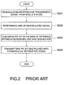
- the receiver 11-n selectively receives a reverse-link (or up-link) transmission signal transmitted by the mobile station 20-n and demodulates it to produce a demodulated reverse-link transmission signal (Step S201).
- the receiver 11-n supplies the demodulated reverse-link transmission signal to both of the decoder 12-n and the SNR determining circuit 13-n.
- the decoder 12-n decodes the demodulated reverse-link transmission signal into a decoded reverse-link signal as a reverse-link information signal. Because the decoded reverse-link signal is unimportant for this invention, nothing will be made about processing for the decoded reverse-link signal in below.
- the SNR determining circuit 13-n determines a signal-to-noise ratio (SNR) of the demodulated reverse-link transmission signal and supplies a SNR signal representing the determined SNR to the TPC bit generator 14-n (Step S202).
- SNR signal-to-noise ratio
- the TPC bit generator 14-n finds a difference between the determined SNR determined by the SNR determining circuit 13-n and a desired SNR memorized therein to generate a transmission power (TPC) bit signal (Step S203).
- TPC transmission power
- the TPC bit generator 14-n When the determined SNR is smaller than the desired SNR, the TPC bit generator 14-n generates a first TPC bit signal as the TPC bit signal on the basis of the difference to require the mobile station 20-n to increase its transmission power.
- the TPC bit generator 14-n Conversely, when the determined SNR is larger than the desired SNR (or the higher threshold), the TPC bit generator 14-n generates a second TPC bit signal as the TPC bit signal on the basis of the difference to require the mobile station 20-n to decrease the transmission power.
- the TPC bit generator 14-n supplies the TPC bit signal to multiplexer 15-n.
- the multiplexer 15-n multiplexes the TPC bit signal with an encoded forward-link information signal for the mobile station 20-n to produce a multiplexed signal.
- error-correcting code is used for the encoded forward-link information signal to correct bit errors caused in a transmission line.
- the multiplexer 15-n supplies the multiplexed signal to the transmitter 16 (Step S204).
- the transmitter 16 multiplexes the multiplexed signal supplied from the multiplexer 15-n and other multiplexed signal the remaining multiplexer 15-1 to 15-N by the use of a code division multiplex to produce a forward-link (or down-link) transmission signal.
- the transmitter 16 transmits the forward-link transmission signal to the mobile stations 20-1 to 20-N.
- the mobile station 20-n receives the forward-link transmission signal.
- the receiver 21-n demodulates the forward-link transmission signal and extracts the multiplexed signal produced by the multiplexer 15-n (Step S301).
- the mobile station 20-n supplies the extracted multiplexed signal to both of the decoder 22-n and the TPC decoder 23-n.
- the decoder 22-n extracts the encoded forward-link information signal from the extracted multiplexed signal and decodes the encoded forward-link information signal into a decoded forward-link information signal (Step S 302). Error detection and correction is made for the decoded forward-link information signal. Because the decoded forward-link information is not important for this invention, no description will be made about processing for the decoded forward-link information signal.
- the TPC bit decoder 23-n extracts the TPC bit signal from the extracted multiplexed signal and decodes the extracted TPC bit signal into a decoded TPC bit signal (Step S303).
- the TPC bit decoder 23-n supplies the decoded TPC bit signal to the transmission power deciding circuit 24.
- the transmission power deciding circuit 24 decides the transmission power of the transmitter 25 in response to the decoded TPC bit signal (Step S304). However, the transmission power deciding circuit 24 restricts the transmission power under a predetermined maximum power.
- the transmitter 25 transmits the reverse-link transmission signal with the decided transmission power decided by the transmission power deciding circuit 24 thereafter (Step S305).
- the conventional transmission power control system makes the mobile stations increase the transmission power.
- the base station also makes the mobile stations increase the transmission power.
- the increase of the transmission power of the mobile stations often makes the SNRs of the demodulated signals at the base station worse.
- the transmission power control system can not decide whether the increase of the transmission power of the mobile station improves the SNRs of the demodulated signals or not.
- the mobile stations waste batteries because they transmit the reverse-link transmission signals with the maximum power in these cases. Furthermore, it makes the interference for adjoining cells large and makes connection capacity of the mobile communication system small that the mobile stations transmit the reverse-link transmission signals with the maximum power.
- the transmission power control system comprises a communication state monitor 41 and a transmission power control bit adjusting circuit 42 in the base station 10.
- the communication state monitor 41 is connected to the SNR determining circuits 13-1 to 13-N while the TPC bit adjusting circuit 42 is connected to the communication state monitor 41, the TPC bit generators 14-1 to 14-N and the multiplexers 15-1 to 15-N.
- the transmission power control system operates according a flowchart illustrated in Fig. 5.
- the communication state monitor 41 receives the SNR signals supplied from the SNR bit determining circuits 13-1 to 13-N and decides whether a communication state between the base station 10 and the mobile stations 20-1 to 20-N keeps worse than a predetermined state for a predetermined time.
- the communication state keeps worse than the predetermined state for the predetermined time, it can be considered that many of the detected SNRs are lower than the desired SNR because of the interference and the detected SNRs can not be improved by increase of the transmission power of the mobile stations.
- the communication state monitor 41 notifies the TPC bit adjusting circuit 42 of quality deterioration of the communication between the base station 10 and the mobile stations 20-1 to 20-N when the communication state keeps worse than the predetermined state for the predetermined time.
- the TPC bit adjusting circuit 42 adjusts the TPC bit signals supplied from the TPC generators 14-1 to 14-N according to the notification of the quality deterioration supplied from the communication state monitor 41 (Step S502).
- the TPC bit adjusting circuit 42 supplies the adjusted TPC bit signals instead of the TPC bit signal generated by the TPC generators 14-1 to 14-N to the multiplexers 15-1 to 15-N.
- the communication state monitor 41 monitors a communication state of a radio communication between the base station 10 and the mobile stations 20-1 to 20-N as follows.
- the communication state monitor 41 finds averages of the determined SNRs per a predetermined time individually on the basis of the SNR signals supplied from the SNR determining circuits 13-1 to 13-N (Step S601).
- the communication state monitor 41 compares each of the averages with a predetermined threshold which is considerably lower than the desired SNR. Then, the communication state monitor 41 counts the number of the averages each of which is lower than the predetermined threshold. Furthermore, the communication sate monitor 41 compares the counted number with a predetermined number (Step S602).
- the communication state monitor 41 judges that the communication state is worse than the predetermined state and notifies the TPC bit adjusting circuit 42 of the quality deterioration (Step S603). On the other hand, the communication state monitor 41 does nothing when the counted number is smaller than the predetermined number.
- the communication state monitor 41 repeats the operation as shown in Fig. 6 at regular time intervals.
- the TPC bit adjusting circuit 42 when the TPC bit adjusting circuit 42 receives the notification of the quality deterioration from the communication state monitor (Step S701), it changes the first TPC bit signals of the TPC bit signals supplied from the TPC bit generator 14-1 to 14-N into the second TPC bit signals predetermined times (Step S702). In this event, the second TPC bit signals require the mobile stations to reduce the transmission power by the fixed value regardless of the difference between the measured SNRs and the desired SNR.
- the second TPC bit signals require the corresponding mobile stations to reduce the transmission power, the interference is suppressed. As a result, it can be avoided that the mobile stations waste batteries and that a connection capacity of the mobile communication system becomes small. Especially, in each of the adjoining cells, because the interference from the cell covered by the base station 10 is reduced, the number of the mobile stations communicating with the base station thereof becomes large.
- the transmission power control system comprising a transmission power control state monitor 81 which is connected to the TPC bit generators 14-1 to 14-N and to the transmission power adjusting circuit 42.
- the transmission power control state monitor 81 operates as illustrated in Fig. 9.
- the transmission power control state monitor 81 monitors the TPC bit signals generated by the TPC bit generators 14-1 to 14-N as the communication state.
- the transmission power control state monitor 81 having timers (not shown) corresponding to the TPC bit generators 14-1 to 14-N respectively. Each of the timers counts time that the corresponding TPC bit generator successively generates the first TPC bit signals as the TPC bit signal.
- the transmission power control state monitor 81 counts the number of the timers each of which counts a time equal to or larger than a predetermined time.
- the transmission power control state monitor 81 compares the counted number of the timers with a predetermined number at a step S902.
- the transmission power control state monitor 81 When the counted number is equal to or larger than the predetermined number, the transmission power control state monitor 81 notifies the transmission power adjusting circuit 42 of the quality deterioration at a step 903. On the other hand, when the counted number is lower than the predetermined number, the transmission power control state monitor 81 does nothing.
- the transmission power control system comprising a transmission power control state monitor 101 which is connected to the receiver 11-1 to 11-N and to the transmission power adjusting circuit 42.
- the transmission power control state monitor 101 operates as illustrated in Fig. 11.
- the transmission power control state monitor 101 receives the demodulated signals from the receiver 11-1 to 11-N and monitors a total electric power of interference included in the demodulated signals as the communication state (Step S1101).
- the transmission power control state monitor 101 compares the total electric power with a predetermined value (Step S902).
- the transmission power control state monitor 101 When the total electric power is equal to or larger than the predetermined value, the transmission power control state monitor 101 notifies the transmission power adjusting circuit 42 of the quality deterioration (Step S903). On the other hand, when the total electric power is lower than the predetermined value, the transmission power control state monitor 101 does nothing.
- the transmission power control system is similar to that of Fig. 10 except for the operation of the transmission power control state monitor 101.
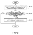
- the transmission power control state monitor 101 operates as illustrated in Fig. 12.
- the transmission power control state monitor 101 receives the demodulated signals from the receiver 11-1 to 11-N.
- the transmission power control state monitor 101 determines not only a total electric power of interference included in the demodulated signals but also the number of the mobile stations communicating with the base station 10 (Step S1201). Then the transmission power control state monitor 101 monitors a ratio of the total electric power to the number of the mobile stations as the communication state.
- the transmission power control state monitor 101 compares a changing rate of the ratio of the total electric power to the number of the mobile stations with a predetermined threshold (Step S1202).
- the transmission power control state monitor 101 When the changing rate is equal-to or larger than the predetermined threshold, the transmission power control state monitor 101 notifies the transmission power adjusting circuit 42 of the quality deterioration (Step S1203). On the other hand, when the changing rate is lower than the predetermined threshold, the transmission power control state monitor 101 does nothing.
- the transmission power control system comprises a TPC bit adjusting circuit 131 which is connected to the TPC bit generators 14-1 to 14-N, the multiplexers 15-1 to 15-N and the communication state monitor 41 (or 81 or 101).
- the TPC bit adjusting circuit 131 operates according to a flowchart of Fig. 14.
- the TPC bit adjusting circuit 131 When the TPC bit adjusting circuit 131 receives the notification of the quality deterioration (Step S1401), it reduces the desired SNRs memorized in the TPC bit generator 14-1 to 14-N (Step S1402).
- the reduction of the desired SNRs decreases the transmission power of the mobile stations. Accordingly, the interference is suppressed and the batteries of the mobile stations are saved. In addition, the connection capacity of the mobile communication system increases.
- the reduction of the desired SNRs may be carried out at either all or selected some of the mobile stations. If the reduction is carried out at all of the mobile stations, it is unnecessary that the TPC bit adjusting circuit 131 receives the TPC bit signals supplied from the TPC bit generators 14-1 to 14-N.
- the selected mobile stations are, for example, those which generate the first TPC bit signals.
- the transmission power of the mobile stations may be maintained when the quality deterioration is detected. This is because it is nothing that at least influence of the interference becomes large by increase of the transmission power of the mobile stations.
Landscapes
- Engineering & Computer Science (AREA)
- Computer Networks & Wireless Communication (AREA)
- Signal Processing (AREA)
- Mobile Radio Communication Systems (AREA)
- Transmitters (AREA)
- Monitoring And Testing Of Transmission In General (AREA)
Applications Claiming Priority (2)
| Application Number | Priority Date | Filing Date | Title |
|---|---|---|---|
| JP2000240547A JP3573073B2 (ja) | 2000-08-09 | 2000-08-09 | 送信電力制御システム及びそれに用いる送信電力制御方法 |
| JP2000240547 | 2000-08-09 |
Publications (3)
| Publication Number | Publication Date |
|---|---|
| EP1179892A2 true EP1179892A2 (fr) | 2002-02-13 |
| EP1179892A3 EP1179892A3 (fr) | 2003-09-24 |
| EP1179892B1 EP1179892B1 (fr) | 2005-04-27 |
Family
ID=18731882
Family Applications (1)
| Application Number | Title | Priority Date | Filing Date |
|---|---|---|---|
| EP01118804A Expired - Lifetime EP1179892B1 (fr) | 2000-08-09 | 2001-08-09 | Système et méthode de commande de la puissance d'émission empêchant la réduction de la capacité de connexion |
Country Status (7)
| Country | Link |
|---|---|
| US (1) | US7813751B2 (fr) |
| EP (1) | EP1179892B1 (fr) |
| JP (1) | JP3573073B2 (fr) |
| KR (1) | KR100418837B1 (fr) |
| CN (1) | CN1162027C (fr) |
| BR (1) | BR0104313A (fr) |
| DE (1) | DE60110329T2 (fr) |
Cited By (2)
| Publication number | Priority date | Publication date | Assignee | Title |
|---|---|---|---|---|
| EP1821423A1 (fr) * | 2006-02-15 | 2007-08-22 | Broadcom Corporation | Procédé et appareil de traitement de commandes de réglage de puissance de transmission dans un réseau AMRC à large bande |
| CN111337920A (zh) * | 2020-03-03 | 2020-06-26 | 成都金宇防务科技有限公司 | 一种防止云雾干扰的弹载雷达对地探测方法及装置 |
Families Citing this family (12)
| Publication number | Priority date | Publication date | Assignee | Title |
|---|---|---|---|---|
| US6904296B2 (en) * | 2001-02-09 | 2005-06-07 | Nokia Mobile Phones Limited | Internal antenna for mobile communications device |
| US7209517B2 (en) * | 2002-03-04 | 2007-04-24 | Qualcomm Incorporated | Method and apparatus for estimating a maximum rate of data and for estimating power required for transmission of data at a rate of data in a communication system |
| US7283851B2 (en) * | 2004-04-05 | 2007-10-16 | Qualcomm Incorporated | Power saving mode for receiver circuit blocks based on transmitter activity |
| US7809395B2 (en) | 2006-02-15 | 2010-10-05 | Broadcom Corporation | Method and system for controlling transmit circuitry in a wide band CDMA network |
| US7907961B2 (en) | 2006-06-07 | 2011-03-15 | Broadcom Corporation | Method and apparatus for improving noise power estimate in a WCDMA network |
| US8050701B2 (en) * | 2006-10-13 | 2011-11-01 | Qualcomm Incorporated | Reverse link power control for wireless communication systems |
| US8005026B2 (en) * | 2007-06-29 | 2011-08-23 | Intel Corporation | Multiple radio platform transmission power control |
| JP2009077284A (ja) * | 2007-09-21 | 2009-04-09 | Japan Radio Co Ltd | 移動機テスタ |
| KR101572880B1 (ko) * | 2007-12-12 | 2015-11-30 | 엘지전자 주식회사 | 다중화율을 고려한 상향링크 전력제어 방법 |
| US8452322B2 (en) * | 2009-02-04 | 2013-05-28 | Lg Electronics Inc. | Method for controlling uplink transmission power in wireless communication system and an apparatus therefor |
| US8634778B1 (en) * | 2010-03-29 | 2014-01-21 | Comtech Ef Data Corp. | Carrier-in-carrier based performance optimization systems and related methods |
| CN102547949B (zh) * | 2010-12-22 | 2015-07-01 | 中国移动通信集团江苏有限公司 | 一种移动通信系统中的功率控制方法和装置 |
Family Cites Families (38)
| Publication number | Priority date | Publication date | Assignee | Title |
|---|---|---|---|---|
| US36056A (en) * | 1862-07-29 | Improvement in rattan machinery | ||
| DE69231437T2 (de) * | 1991-12-26 | 2001-03-01 | Nec Corp., Tokio/Tokyo | System zur Steuerung der Sendeleistung mit Gewährleistung einer konstanten Signalqualität in einem Mobilkommunikationsnetzwerk |
| US5333175A (en) * | 1993-01-28 | 1994-07-26 | Bell Communications Research, Inc. | Method and apparatus for dynamic power control in TDMA portable radio systems |
| JPH07264660A (ja) * | 1994-03-18 | 1995-10-13 | Fujitsu Ltd | 移動通信モニタ方式 |
| US5859874A (en) * | 1994-05-09 | 1999-01-12 | Globalstar L.P. | Multipath communication system optimizer |
| JP2993554B2 (ja) | 1994-05-12 | 1999-12-20 | エヌ・ティ・ティ移動通信網株式会社 | 送信電力制御法および前記送信電力制御法を用いた通信装置 |
| JP2974274B2 (ja) | 1994-05-12 | 1999-11-10 | エヌ・ティ・ティ移動通信網株式会社 | 送信電力制御方法および送信電力制御装置 |
| JPH088802A (ja) * | 1994-06-22 | 1996-01-12 | N T T Ido Tsushinmo Kk | 移動無線機 |
| US5603096A (en) * | 1994-07-11 | 1997-02-11 | Qualcomm Incorporated | Reverse link, closed loop power control in a code division multiple access system |
| US5822318A (en) * | 1994-07-29 | 1998-10-13 | Qualcomm Incorporated | Method and apparatus for controlling power in a variable rate communication system |
| JP2798012B2 (ja) | 1995-07-14 | 1998-09-17 | 日本電気株式会社 | 基地局送信電力制御装置および方法 |
| WO1997008847A1 (fr) * | 1995-08-31 | 1997-03-06 | Nokia Telecommunications Oy | Procede de regulation de la puissance d'emission d'un emetteur radio dans un systeme de communication cellulaire |
| JP3039402B2 (ja) | 1996-12-05 | 2000-05-08 | 日本電気株式会社 | 移動通信システムの送信電力制御装置 |
| JP2785809B2 (ja) * | 1996-06-21 | 1998-08-13 | 日本電気株式会社 | リバースチャネル送信電力制御方式 |
| JP3111906B2 (ja) * | 1996-07-17 | 2000-11-27 | 日本電気株式会社 | 無線基地局装置 |
| JP3254390B2 (ja) | 1996-10-18 | 2002-02-04 | 三菱電機株式会社 | 送信電力制御装置 |
| EP0856955A3 (fr) * | 1997-01-29 | 2000-09-06 | YRP Mobile Telecommunications Key Technology Research Laboratories Co., Ltd. | Régulation de puissance dans un système AMDC |
| JP3586348B2 (ja) | 1997-03-05 | 2004-11-10 | 富士通株式会社 | 信号対干渉電力比測定装置及び信号対干渉電力比測定方法並びにcdma通信方式下での送信電力制御方法 |
| KR100243425B1 (ko) * | 1997-07-10 | 2000-02-01 | 곽치영 | 씨디엠에이 무선가입자망 시스템의 순방향 트래픽 채널 전력제어 방법 및 장치 |
| JP3132427B2 (ja) * | 1997-07-11 | 2001-02-05 | 日本電気株式会社 | S/n測定回路,送信電力制御装置,及びディジタル通信システム |
| US6185432B1 (en) | 1997-10-13 | 2001-02-06 | Qualcomm Incorporated | System and method for selecting power control modes |
| KR100369602B1 (ko) * | 1997-11-03 | 2003-04-11 | 삼성전자 주식회사 | 부호분할다중접속방식이동통신시스템의전력제어비트삽입방법 |
| JP3355295B2 (ja) * | 1997-11-13 | 2002-12-09 | 松下電器産業株式会社 | 送信電力制御方法及び送受信装置 |
| JPH11196456A (ja) * | 1998-01-05 | 1999-07-21 | Oki Electric Ind Co Ltd | 送信電力制御装置 |
| JPH11275035A (ja) | 1998-01-26 | 1999-10-08 | Matsushita Electric Ind Co Ltd | 移動局通信装置、基地局通信装置及び無線通信システム |
| JP2970653B1 (ja) | 1998-05-27 | 1999-11-02 | 日本電気株式会社 | スペクトラム拡散通信システムとその基地局 |
| US6256476B1 (en) * | 1998-06-25 | 2001-07-03 | Conexant Systems, Inc. | Power management for a telephone system by dynamically adjusting transmission power |
| JP3471662B2 (ja) * | 1998-08-28 | 2003-12-02 | 松下電器産業株式会社 | 送受信装置及びその送信電力制御方法 |
| KR20000022672A (ko) | 1998-09-07 | 2000-04-25 | 마츠시타 덴끼 산교 가부시키가이샤 | 이동국 통신 장치, 기지국 통신 장치 및 무선 통신 방법 |
| KR100277071B1 (ko) | 1998-09-15 | 2001-01-15 | 윤종용 | 셀룰러시스템의역방향전력제어방법 |
| JP3199238B2 (ja) | 1998-09-18 | 2001-08-13 | 日本電気株式会社 | 符号分割多元接続方式における送信電力制御システム及び送信電力制御方法 |
| US6956840B1 (en) * | 1998-09-21 | 2005-10-18 | Ipr Licensing, Inc. | Power control protocol for highly variable data rate reverse link of a wireless communication system |
| US6717976B1 (en) * | 1998-12-21 | 2004-04-06 | Nortel Networks Ltd. | Method and apparatus for signal to noise power ratio estimation in a multi sub-channel CDMA receiver |
| US7076264B2 (en) * | 1999-02-19 | 2006-07-11 | Qualcomm, Inc. | Power control in a cellular system using ES/IO and NT/I0 values |
| US6603746B1 (en) * | 1999-06-18 | 2003-08-05 | Nortel Networks Limited | Method and apparatus for controlling transmitted power in a wireless communications system |
| US6633552B1 (en) * | 1999-08-06 | 2003-10-14 | Qualcomm Incorporated | Method and apparatus for determining the closed loop power control set point in a wireless packet data communication system |
| US6697343B1 (en) * | 1999-08-26 | 2004-02-24 | Lucent Technologies Inc. | Method and apparatus for controlling power for variable-rate vocoded communications |
| JP3389951B2 (ja) * | 2000-02-07 | 2003-03-24 | 日本電気株式会社 | Cdma移動通信システム及び該cdma移動通信システムにおける下り回線送信電力制御方法 |
-
2000
- 2000-08-09 JP JP2000240547A patent/JP3573073B2/ja not_active Expired - Fee Related
-
2001
- 2001-08-03 BR BR0104313-7A patent/BR0104313A/pt not_active Application Discontinuation
- 2001-08-09 US US09/924,723 patent/US7813751B2/en not_active Expired - Fee Related
- 2001-08-09 KR KR10-2001-0047893A patent/KR100418837B1/ko not_active Expired - Fee Related
- 2001-08-09 CN CNB011238836A patent/CN1162027C/zh not_active Expired - Fee Related
- 2001-08-09 EP EP01118804A patent/EP1179892B1/fr not_active Expired - Lifetime
- 2001-08-09 DE DE60110329T patent/DE60110329T2/de not_active Expired - Lifetime
Cited By (4)
| Publication number | Priority date | Publication date | Assignee | Title |
|---|---|---|---|---|
| EP1821423A1 (fr) * | 2006-02-15 | 2007-08-22 | Broadcom Corporation | Procédé et appareil de traitement de commandes de réglage de puissance de transmission dans un réseau AMRC à large bande |
| EP2017970A1 (fr) * | 2006-02-15 | 2009-01-21 | Broadcom Corporation | Procédé et appareil pour traiter les commandes de puissance d'émission (TPC) dans un réseau CDMA (WCDMA) à large bande |
| CN101022297B (zh) * | 2006-02-15 | 2011-04-13 | 美国博通公司 | Wcdma网络中处理发射功率控制指令的方法和系统 |
| CN111337920A (zh) * | 2020-03-03 | 2020-06-26 | 成都金宇防务科技有限公司 | 一种防止云雾干扰的弹载雷达对地探测方法及装置 |
Also Published As
| Publication number | Publication date |
|---|---|
| DE60110329D1 (de) | 2005-06-02 |
| JP3573073B2 (ja) | 2004-10-06 |
| US20020018516A1 (en) | 2002-02-14 |
| KR20020013448A (ko) | 2002-02-20 |
| US7813751B2 (en) | 2010-10-12 |
| KR100418837B1 (ko) | 2004-02-18 |
| DE60110329T2 (de) | 2005-10-06 |
| CN1162027C (zh) | 2004-08-11 |
| BR0104313A (pt) | 2002-03-19 |
| CN1337833A (zh) | 2002-02-27 |
| JP2002057634A (ja) | 2002-02-22 |
| EP1179892A3 (fr) | 2003-09-24 |
| EP1179892B1 (fr) | 2005-04-27 |
Similar Documents
| Publication | Publication Date | Title |
|---|---|---|
| EP0548939B1 (fr) | Système de commande de puissance d'émission permettant de garder une qualité constante du signal dans un réseau de communication mobile | |
| KR100723106B1 (ko) | 기지국의 전송 파워 레벨 제어 방법 | |
| EP1179892B1 (fr) | Système et méthode de commande de la puissance d'émission empêchant la réduction de la capacité de connexion | |
| US6526028B1 (en) | CDMA mobile communication system with consideration of fading | |
| EP1209824B1 (fr) | Unite de station de base et procede de radiocommunication | |
| US6208861B1 (en) | Mobile terminal with GPS function | |
| US5930242A (en) | Transmitting power control method and apparatus | |
| EP0809365B1 (fr) | Commande des puissances pendant la commutation douce dans un système de communication mobile à accès multiple par division de code | |
| CA2266810C (fr) | Methode de controle de la puissance d'emission d'un systeme cellulaire et appareil de station de base | |
| EP1113589B1 (fr) | Reglage de debit sur base du trafic et de la puissance d'émission | |
| EP1502376B1 (fr) | Procede et appareil de synchronisation de transmission montante dans un systeme de communication mobile | |
| KR100763005B1 (ko) | 이동 통신 시스템 | |
| EP1455548B1 (fr) | Procédé pour l'établissement d'un seuil pour un interrupteur de l'alimentation d'un terminal de communication mobile | |
| EP1435744B1 (fr) | Station de base et procédé de selection d un canal de trafic | |
| EP0812121B1 (fr) | Méthode de transmission de canaux sémaphores et de sélection de cellule dans un système de communication AMRC | |
| MXPA01012708A (es) | Metodo y aparato para determinar una velocidad de transmision de enlace inverso en un sistema de comunicacion inalambrica. | |
| EP1247418B1 (fr) | Fonctionnement optimise en mode veille | |
| EP1414261A2 (fr) | Système cellulaire | |
| US20030153272A1 (en) | Quality threshold setting method and communication controller using the method | |
| JP2000503514A (ja) | 動的なチャンネル割り当て | |
| EP1069702A2 (fr) | Synchronisation des réglages du niveau de puissance émise durant une commutation douce dans un système sans fil au moyen de contraintes sur le niveau de puissance | |
| EP1119117A1 (fr) | Station de base, terminal de transmission et procede de commande de la puissance de transmission | |
| EP1745565B1 (fr) | Système de communication, station primaire et procédé de commande de puissance de transmission | |
| KR100340831B1 (ko) | 확산 스펙트럼 통신 시스템 및 기지국 | |
| WO2001018991A1 (fr) | Selection de liaison dans un systeme de communications |
Legal Events
| Date | Code | Title | Description |
|---|---|---|---|
| PUAI | Public reference made under article 153(3) epc to a published international application that has entered the european phase |
Free format text: ORIGINAL CODE: 0009012 |
|
| AK | Designated contracting states |
Kind code of ref document: A2 Designated state(s): AT BE CH CY DE DK ES FI FR GB GR IE IT LI LU MC NL PT SE TR |
|
| AX | Request for extension of the european patent |
Free format text: AL;LT;LV;MK;RO;SI |
|
| PUAL | Search report despatched |
Free format text: ORIGINAL CODE: 0009013 |
|
| AK | Designated contracting states |
Kind code of ref document: A3 Designated state(s): AT BE CH CY DE DK ES FI FR GB GR IE IT LI LU MC NL PT SE TR |
|
| AX | Request for extension of the european patent |
Extension state: AL LT LV MK RO SI |
|
| 17P | Request for examination filed |
Effective date: 20030819 |
|
| 17Q | First examination report despatched |
Effective date: 20040112 |
|
| AKX | Designation fees paid |
Designated state(s): DE GB |
|
| GRAP | Despatch of communication of intention to grant a patent |
Free format text: ORIGINAL CODE: EPIDOSNIGR1 |
|
| GRAS | Grant fee paid |
Free format text: ORIGINAL CODE: EPIDOSNIGR3 |
|
| GRAA | (expected) grant |
Free format text: ORIGINAL CODE: 0009210 |
|
| AK | Designated contracting states |
Kind code of ref document: B1 Designated state(s): DE GB |
|
| REG | Reference to a national code |
Ref country code: GB Ref legal event code: FG4D |
|
| REG | Reference to a national code |
Ref country code: IE Ref legal event code: FG4D |
|
| REF | Corresponds to: |
Ref document number: 60110329 Country of ref document: DE Date of ref document: 20050602 Kind code of ref document: P |
|
| PLBE | No opposition filed within time limit |
Free format text: ORIGINAL CODE: 0009261 |
|
| STAA | Information on the status of an ep patent application or granted ep patent |
Free format text: STATUS: NO OPPOSITION FILED WITHIN TIME LIMIT |
|
| 26N | No opposition filed |
Effective date: 20060130 |
|
| PGFP | Annual fee paid to national office [announced via postgrant information from national office to epo] |
Ref country code: DE Payment date: 20170801 Year of fee payment: 17 Ref country code: GB Payment date: 20170809 Year of fee payment: 17 |
|
| REG | Reference to a national code |
Ref country code: DE Ref legal event code: R119 Ref document number: 60110329 Country of ref document: DE |
|
| GBPC | Gb: european patent ceased through non-payment of renewal fee |
Effective date: 20180809 |
|
| PG25 | Lapsed in a contracting state [announced via postgrant information from national office to epo] |
Ref country code: DE Free format text: LAPSE BECAUSE OF NON-PAYMENT OF DUE FEES Effective date: 20190301 |
|
| PG25 | Lapsed in a contracting state [announced via postgrant information from national office to epo] |
Ref country code: GB Free format text: LAPSE BECAUSE OF NON-PAYMENT OF DUE FEES Effective date: 20180809 |