EP1179958A1 - Image processing device and monitoring system - Google Patents
Image processing device and monitoring system Download PDFInfo
- Publication number
- EP1179958A1 EP1179958A1 EP00915550A EP00915550A EP1179958A1 EP 1179958 A1 EP1179958 A1 EP 1179958A1 EP 00915550 A EP00915550 A EP 00915550A EP 00915550 A EP00915550 A EP 00915550A EP 1179958 A1 EP1179958 A1 EP 1179958A1
- Authority
- EP
- European Patent Office
- Prior art keywords
- image
- vehicle
- image processing
- view
- synthetic
- Prior art date
- Legal status (The legal status is an assumption and is not a legal conclusion. Google has not performed a legal analysis and makes no representation as to the accuracy of the status listed.)
- Granted
Links
Images


Classifications
-
- H—ELECTRICITY
- H04—ELECTRIC COMMUNICATION TECHNIQUE
- H04N—PICTORIAL COMMUNICATION, e.g. TELEVISION
- H04N7/00—Television systems
- H04N7/18—Closed-circuit television [CCTV] systems, i.e. systems in which the video signal is not broadcast
-
- G—PHYSICS
- G06—COMPUTING OR CALCULATING; COUNTING
- G06T—IMAGE DATA PROCESSING OR GENERATION, IN GENERAL
- G06T15/00—Three-dimensional [3D] image rendering
- G06T15/10—Geometric effects
- G06T15/20—Perspective computation
- G06T15/205—Image-based rendering
-
- B—PERFORMING OPERATIONS; TRANSPORTING
- B60—VEHICLES IN GENERAL
- B60R—VEHICLES, VEHICLE FITTINGS, OR VEHICLE PARTS, NOT OTHERWISE PROVIDED FOR
- B60R1/00—Optical viewing arrangements; Real-time viewing arrangements for drivers or passengers using optical image capturing systems, e.g. cameras or video systems specially adapted for use in or on vehicles
- B60R1/20—Real-time viewing arrangements for drivers or passengers using optical image capturing systems, e.g. cameras or video systems specially adapted for use in or on vehicles
- B60R1/22—Real-time viewing arrangements for drivers or passengers using optical image capturing systems, e.g. cameras or video systems specially adapted for use in or on vehicles for viewing an area outside the vehicle, e.g. the exterior of the vehicle
- B60R1/23—Real-time viewing arrangements for drivers or passengers using optical image capturing systems, e.g. cameras or video systems specially adapted for use in or on vehicles for viewing an area outside the vehicle, e.g. the exterior of the vehicle with a predetermined field of view
- B60R1/27—Real-time viewing arrangements for drivers or passengers using optical image capturing systems, e.g. cameras or video systems specially adapted for use in or on vehicles for viewing an area outside the vehicle, e.g. the exterior of the vehicle with a predetermined field of view providing all-round vision, e.g. using omnidirectional cameras
-
- B—PERFORMING OPERATIONS; TRANSPORTING
- B60—VEHICLES IN GENERAL
- B60R—VEHICLES, VEHICLE FITTINGS, OR VEHICLE PARTS, NOT OTHERWISE PROVIDED FOR
- B60R1/00—Optical viewing arrangements; Real-time viewing arrangements for drivers or passengers using optical image capturing systems, e.g. cameras or video systems specially adapted for use in or on vehicles
- B60R1/20—Real-time viewing arrangements for drivers or passengers using optical image capturing systems, e.g. cameras or video systems specially adapted for use in or on vehicles
- B60R1/22—Real-time viewing arrangements for drivers or passengers using optical image capturing systems, e.g. cameras or video systems specially adapted for use in or on vehicles for viewing an area outside the vehicle, e.g. the exterior of the vehicle
- B60R1/28—Real-time viewing arrangements for drivers or passengers using optical image capturing systems, e.g. cameras or video systems specially adapted for use in or on vehicles for viewing an area outside the vehicle, e.g. the exterior of the vehicle with an adjustable field of view
-
- G—PHYSICS
- G03—PHOTOGRAPHY; CINEMATOGRAPHY; ANALOGOUS TECHNIQUES USING WAVES OTHER THAN OPTICAL WAVES; ELECTROGRAPHY; HOLOGRAPHY
- G03B—APPARATUS OR ARRANGEMENTS FOR TAKING PHOTOGRAPHS OR FOR PROJECTING OR VIEWING THEM; APPARATUS OR ARRANGEMENTS EMPLOYING ANALOGOUS TECHNIQUES USING WAVES OTHER THAN OPTICAL WAVES; ACCESSORIES THEREFOR
- G03B37/00—Panoramic or wide-screen photography; Photographing extended surfaces, e.g. for surveying; Photographing internal surfaces, e.g. of pipe
- G03B37/04—Panoramic or wide-screen photography; Photographing extended surfaces, e.g. for surveying; Photographing internal surfaces, e.g. of pipe with cameras or projectors providing touching or overlapping fields of view
-
- G—PHYSICS
- G06—COMPUTING OR CALCULATING; COUNTING
- G06T—IMAGE DATA PROCESSING OR GENERATION, IN GENERAL
- G06T3/00—Geometric image transformations in the plane of the image
- G06T3/40—Scaling of whole images or parts thereof, e.g. expanding or contracting
- G06T3/4038—Image mosaicing, e.g. composing plane images from plane sub-images
-
- H—ELECTRICITY
- H04—ELECTRIC COMMUNICATION TECHNIQUE
- H04N—PICTORIAL COMMUNICATION, e.g. TELEVISION
- H04N7/00—Television systems
- H04N7/18—Closed-circuit television [CCTV] systems, i.e. systems in which the video signal is not broadcast
- H04N7/181—Closed-circuit television [CCTV] systems, i.e. systems in which the video signal is not broadcast for receiving images from a plurality of remote sources
-
- B—PERFORMING OPERATIONS; TRANSPORTING
- B60—VEHICLES IN GENERAL
- B60R—VEHICLES, VEHICLE FITTINGS, OR VEHICLE PARTS, NOT OTHERWISE PROVIDED FOR
- B60R2300/00—Details of viewing arrangements using cameras and displays, specially adapted for use in a vehicle
- B60R2300/10—Details of viewing arrangements using cameras and displays, specially adapted for use in a vehicle characterised by the type of camera system used
- B60R2300/102—Details of viewing arrangements using cameras and displays, specially adapted for use in a vehicle characterised by the type of camera system used using 360 degree surveillance camera system
-
- B—PERFORMING OPERATIONS; TRANSPORTING
- B60—VEHICLES IN GENERAL
- B60R—VEHICLES, VEHICLE FITTINGS, OR VEHICLE PARTS, NOT OTHERWISE PROVIDED FOR
- B60R2300/00—Details of viewing arrangements using cameras and displays, specially adapted for use in a vehicle
- B60R2300/10—Details of viewing arrangements using cameras and displays, specially adapted for use in a vehicle characterised by the type of camera system used
- B60R2300/105—Details of viewing arrangements using cameras and displays, specially adapted for use in a vehicle characterised by the type of camera system used using multiple cameras
-
- B—PERFORMING OPERATIONS; TRANSPORTING
- B60—VEHICLES IN GENERAL
- B60R—VEHICLES, VEHICLE FITTINGS, OR VEHICLE PARTS, NOT OTHERWISE PROVIDED FOR
- B60R2300/00—Details of viewing arrangements using cameras and displays, specially adapted for use in a vehicle
- B60R2300/60—Details of viewing arrangements using cameras and displays, specially adapted for use in a vehicle characterised by monitoring and displaying vehicle exterior scenes from a transformed perspective
- B60R2300/607—Details of viewing arrangements using cameras and displays, specially adapted for use in a vehicle characterised by monitoring and displaying vehicle exterior scenes from a transformed perspective from a bird's eye viewpoint
-
- B—PERFORMING OPERATIONS; TRANSPORTING
- B60—VEHICLES IN GENERAL
- B60R—VEHICLES, VEHICLE FITTINGS, OR VEHICLE PARTS, NOT OTHERWISE PROVIDED FOR
- B60R2300/00—Details of viewing arrangements using cameras and displays, specially adapted for use in a vehicle
- B60R2300/80—Details of viewing arrangements using cameras and displays, specially adapted for use in a vehicle characterised by the intended use of the viewing arrangement
- B60R2300/806—Details of viewing arrangements using cameras and displays, specially adapted for use in a vehicle characterised by the intended use of the viewing arrangement for aiding parking
-
- G—PHYSICS
- G06—COMPUTING OR CALCULATING; COUNTING
- G06T—IMAGE DATA PROCESSING OR GENERATION, IN GENERAL
- G06T2200/00—Indexing scheme for image data processing or generation, in general
- G06T2200/32—Indexing scheme for image data processing or generation, in general involving image mosaicing
Definitions
- the present invention relates to an image processing technique for generating synthetic images with images captured by a plurality of cameras.
- the present invention relates to an effective technique for a monitoring system that can be utilized as an aid to confirm safety when driving a vehicle.
- monitors are prepared in the number corresponding to the number of the cameras installed for monitoring.
- a conventional safety monitoring system for vehicles is as follows.
- a camera for capturing images is installed around the vehicle, and the images captured by the camera are displayed on a monitor installed near the driving seat.
- This system allows the driver to confirm safety of places of which safety confirmation is difficult with eyes or a mirror, such as an area behind the vehicle, through the monitor.
- Japanese Patent Publication No. 2696516 discloses a structure that displays images on a divided monitoring screen, depending on the gear or the car speed. More specifically, when it is determined that the vehicle is in the halt state or in the low speed state, the monitoring screen is divided into three sections, and images captured by three cameras installed on the right side, the left side and in a lower portion of the vehicle are synthesized and reproduced. When it is determined that the vehicle is in the forward running state, the monitoring screen is divided into two sections, and images captured by two cameras installed on the right side and the left side of the vehicle are synthesized and reproduced.
- Japanese Laid-Open Patent Publication No. 11-78692 discloses a video presenting apparatus for vehicles having a structure in which precise videos for each encountered scene are synthesized and displayed. More specifically, camera images are transformed and synthesized depending on the driving state of the vehicle such as backward parking, forward parking, parallel parking or a state where the vehicle goes into an intersection with an obstructed view.
- an image processing apparatus of the present invention includes an image processing part for receiving images captured by a plurality of cameras shooting surroundings of a vehicle to generate a synthetic image viewed from a virtual point of view from these camera images, wherein the image processing part changes at least one selected from the position, the direction of the line of sight, and the focal length of the virtual point of view in accordance with a running state of the vehicle.
- the image processing part changes at least one selected from the position of the virtual point of view, the direction of the line of sight, and the focal length in accordance with a running speed of the vehicle.
- the image processing part changes at least one selected from the position, the direction of the line of sight, and the focal length of the virtual point of view, and controls capturing of an image outside a view range of the changed virtual point of view.
- the image processing part controls the capturing of an image outside a view range of the changed virtual point of view by changing a model for image synthesis.
- the image processing part changes at least one selected from the position, the direction of the line of sight, and the focal length of the virtual point of view in accordance with a steering angle of the vehicle.
- the image processing part changes at least one selected from the position, the direction of the line of sight, and the focal length of the virtual point of view in accordance with results of. detection by an object detecting sensor that is provided in the vehicle.
- the image processing part includes an original mapping table and generates a synthetic image using a mapping table that is cut out from the original mapping table, and the image processing part changes at least one selected from the position, the direction of the line of sight, and the focal length of the virtual point of view by changing the mapping table to be cut out from the original mapping table.
- an image processing apparatus includes an image processing part for receiving images captured by a plurality of cameras shooting surroundings of a vehicle to generate a synthetic image viewed from a virtual point of view from these camera images, wherein the image processing part controls capturing of an image outside a view range of the virtual point of view in accordance with a running state of the vehicle.
- a monitoring system includes a plurality of cameras shooting surroundings of a vehicle; an image processing part for receiving images captured by the plurality of cameras to generate a synthetic image viewed from a virtual point of view from these camera images; and a display part for displaying the synthetic image, wherein the image processing part changes at least one selected from the position, the direction of the line of sight, and the focal length of the virtual point of view in accordance with a running state of the vehicle.
- an image processing apparatus of the present invention includes an image processing part for receiving images captured by a plurality of cameras shooting surroundings of a vehicle to generate a synthetic image from these camera images, wherein the image processing part generates an image including a first image and a second image as the synthetic image, the first image being viewed from a virtual point of view, the second image being viewed from a viewpoint that is different from the virtual point of view of the first image in at least one selected from the position, the direction of the line of sight and the focal length, or the second image being different from the first image in the model.
- the second image is at least one of the camera images.
- the first image is a close view image showing the vehicle and surroundings thereof
- the second image is a distant view image showing an area distant from the surrounding area of the vehicle that is shown by the close view image.
- the image processing part arranges the distant view image around the close view image in the synthetic image.
- the distant view image is an image having continuity with the close view image.
- the first image shows at least a part of the vehicle and at least a part of the surroundings of the vehicle
- the second image is obtained by enlarging at least a part of the area shown by the first image
- a monitoring system includes a plurality of cameras shooting surroundings of a vehicle; an image processing part for receiving images captured by the plurality of cameras to generate a synthetic image from these camera images; and a display part for displaying the synthetic image, wherein the image processing part generates an image including a first image and a second image as the synthetic image, the first image being viewed from a virtual point of view, the second image being viewed from a viewpoint that is different from the virtual point of view of the first image in at least one selected from the position, the direction of the line of sight and the focal length, or the second image being different from the first image in the model.
- an image processing apparatus of the present invention includes an image processing part for receiving images captured by a plurality of cameras shooting surroundings of a vehicle to generate a synthetic image from these camera images, wherein in the synthetic image, the image processing part displays at least a part of a vehicle region where the vehicle is present, and an attention drawing region for drawing attention in which at least a part of the surroundings of the vehicle is shown.
- the synthetic image is an image viewed from a virtual point of view that is set above the vehicle.
- the image processing part displays an illustration image or an actual image of the vehicle on the vehicle region.
- the attention drawing region includes at least a part of a blind spot region around the vehicle that is not shot by any of the cameras. Alternatively, it is preferable that the attention drawing region corresponds to the blind spot region around the vehicle that is not shot by any of the cameras. It is preferable that the image processing part determines a range of a region obtained by combining the blind spot region and the vehicle region, using region data showing a projection region of the vehicle in each camera image.
- a monitoring system includes a plurality of cameras shooting surroundings of a vehicle; an image processing part for receiving images captured by the plurality of cameras to generate a synthetic image from these camera images; and a display part for displaying the synthetic image, wherein in the synthetic image, the image processing part displays at least a part of a vehicle region where the vehicle is present, and an attention drawing region for drawing attention in which at least a part of the surroundings of the vehicle is shown.
- an image processing apparatus of the present invention includes an image processing part for receiving images captured by a plurality of cameras shooting surroundings of a vehicle to generate a synthetic image from these camera images, wherein the image processing part generates the synthetic image, using a mapping table including first mapping data describing a correspondence relationship between pixels of the synthetic image and pixels of the camera images, and second mapping data describing an identifier showing that a pixel of the synthetic image corresponds to pixel data other than the camera images.
- the pixel data other than the camera images shows the vehicle or a blind spot region that is present in at least a part of the surroundings of the vehicle.
- the image processing part stores a predetermined image other than the camera images, and with respect to the pixel of the synthetic image, the second mapping data describes coordinate values in the stored predetermined image corresponding to the pixel.
- the second mapping data describes pixel data corresponding to the pixel of the synthetic image.
- an image processing apparatus includes an image processing part for receiving images captured by a plurality of cameras shooting surroundings of a vehicle to generate a synthetic image from these camera images, wherein the image processing part uses mapping data describing a correspondence relationship between pixels of the synthetic image and a plurality of pixel data including one or both of pixel data of the camera images and pixel data other than the camera images, and describing the rate of necessity with respect to each of the pixel data, and weights each pixel data in accordance with the rate of necessity, thereby generating the pixel data of the pixels of the synthetic image.
- an image processing apparatus includes an image processing part for receiving images captured by a plurality of cameras shooting surroundings of a vehicle to generate a synthetic image from these camera images, wherein the image processing part includes an original mapping table, cuts out a mapping table describing a correspondence relationship between pixels of the synthetic image and pixels of the camera images, and generates the synthetic image, using the cut-out mapping table.
- Fig. 1 is a conceptual diagram of a monitoring system of the present invention.
- Figs. 2(a) and 2(b) are views showing an example of camera arrangement.
- Fig. 3 is an example of images captured by the cameras of Figs. 2(a) and 2(b).
- Fig. 4 is a view conceptually showing the relationship between a virtual point of view and actual cameras.
- Fig. 5 is an example of a generated synthetic image.
- Figs 6(a) to 6(e) are views showing an image synthesis operation using a mapping table.
- Fig. 7 is an example of a structure of a monitoring system of an embodiment of the present invention.
- Fig. 8 is a flowchart showing an operation of an image synthesis part of Fig. 7.
- Fig. 9 is an example of a structure of a mapping table.
- Fig. 10 is a flowchart showing the detail of the pixel synthesis step S14 of Fig. 8.
- Fig. 11 is an example of mapping data that describe pixel data other than the camera images.
- Fig. 12 is an example of a vertically downward view image utilizing images from eight cameras.
- Fig. 13 is an example of a vertically downward view image utilizing images from four cameras.
- Fig. 14 is an example of a vertically downward view image utilizing images from two cameras.
- Fig. 15 is an example of an obliquely downward view image.
- Fig. 16 is an example of a panorama image in forward panorama mode.
- Fig. 17 is an example of a panorama image in backward panorama mode.
- Fig. 18 is an example of a combination of an obliquely downward view image and a panorama image.
- Figs. 19(a) to 19(f) show an example of synthetic images when the height of the virtual point of view is changed in accordance with the running state of the vehicle.
- Figs. 20(a) to 20(d) show an example of synthetic images when the direction of the line of sight of the virtual point of view is changed in accordance with the running state of the vehicle.
- Figs. 21(a) and 21(b) show an example of synthetic images when the direction of the line of sight of the virtual point of view is changed in accordance with the steering angle of the vehicle.
- Figs. 22(a) and 22(b) are views showing an example of image switching in accordance with output signals from an object detecting sensor.
- Fig. 23 is a view showing an example of image switching in accordance with output signals of an object detecting sensor.
- Fig. 24 shows views showing an example of image switching in accordance with output signals of an object detecting sensor.
- Fig. 25 is an example of a structure of a monitoring system of an embodiment of the present invention.
- Figs. 26(a) to 26(d) are views showing cutting-out of a mapping table for parallel displacement of an image.
- Figs. 27(a) to 27(g) are views showing cutting-out of a mapping table for enlargement or contraction of an image.
- Fig. 28 is a view showing cutting-out of a mapping table in the shape of a quadrangle other than a square.
- Fig. 29 is an example of camera images.
- Fig. 30 is an example of a synthetic image where camera images showing an obliquely backward view is attached on the right and the left of a downward view image.
- Fig. 31 is an example displaying a downward view image in a narrow range and a downward view image in a wide range side by side.
- Fig. 32 is an example where obliquely downward view images are attached around the downward view image.
- Fig. 33 is an example where an image utilizing a quasi-cylindrical model is attached around the downward view image.
- Fig. 34 is an example where panorama images are attached around the downward view image.
- Fig. 35 is an example where obliquely downward view images are attached around the downward view image with blank portions at the four corners.
- Fig. 36 is an example displaying an image showing the position of a virtual point of view together with a camera image.
- Fig. 37 shows views showing an example of camera images and mask data showing projection regions of the vehicle.
- Figs. 38(a) to 38(c) are views showing an example where an image of the vehicle is superimposed.
- Fig. 39 shows views showing an example of synthetic images when a projection of the vehicle is converted as it is.
- Fig. 40 shows views showing a part of the mask data.
- Fig. 41 is an example of a synthetic image showing a vehicle region and a blind spot region.
- Fig. 42 is a diagram showing a procedure for generating mapping data for obtaining the blind spot region and attaching images of a vehicle.
- Figs. 43(a) to 43(d) are diagrams showing the relationship between the mask data and the pixels of the synthetic images.
- Figs 44(a) to 44(c) show an example of synthetic images when mapping data obtained as a result of the procedure of Fig. 42 are used.
- Fig. 45 is a diagram showing a procedure for generating mapping data for designating an attention drawing region.
- Figs. 46(a) to 46(c) show an example of synthetic images when mapping data obtained as a result of the procedure of Fig. 45 are used.
- Fig. 47 is a diagram for illustrating geometric transformation.
- Fig. 48 is a diagram for illustrating geometric transformation.
- Fig. 49 is a diagram for illustrating geometric transformation.
- Fig. 50 is a diagram for illustrating geometric transformation.
- Fig. 1 is a conceptual diagram of a monitoring system of the present invention.
- an image processing part 2 receives a plurality of camera images output from an image capturing part 1 , and synthesizes the images to generate a synthesis image viewed from a virtual point of view. This synthetic image is displayed by a displaying part 3 such as a liquid crystal display.
- the image processing part 2 constitutes an image processing apparatus of the present invention.
- a monitoring system of the present invention is mounted on a vehicle to assist parking or the like.
- Figs. 2(a) and 2(b) show an example of camera arrangement.
- Fig. 3 is an example of images captured by the cameras arranged in Figs. 2(a) and 2(b).
- five cameras are provided in the vicinity of the door mirror, in the vicinity of the rear pillar and on the rear trunk.
- the image processing part 2 generates a synthetic image from five camera images when viewed from a virtual point of view.
- the virtual point of view can be set to be oriented to an arbitrary direction in an arbitrary position in a three-dimensional space as in the case of a camera arrangement in video generation of computer graphics.
- the parameters that determine the virtual point of view are coordinates (X-axis, Y-axis, Z-axis) representing the position of the virtual point of view in a three-dimensional space, three angles representing the direction, namely, an azimuth (horizontal rotation), an elevation angle (gradient) and a twist (rotation about the optical axis), and a focal length defining the view range.
- the focal length is a distance between the virtual point of view and a projection plane on which a synthetic image is generated. When the focal length is small, an image with a wide angle is generated.
- the focal length When the focal length is large, a telescopic image is generated. In actual cameras, the focal length is often represented by a distance (mm) with respect to the size (35mm) of a film that is the projection plane. In this specification, since the size of a synthetic image is represented by pixels, the focal length is also represented by pixels.
- An appropriate synthetic image can be generated by selecting the position, the direction and the focal length of the virtual point of view depending on the situation.
- Fig. 4 is a view conceptually showing the relationship between a virtual point of view and actual cameras.
- the virtual point of view is set above the vehicle.
- Fig. 5 is an example of a generated synthetic image, which is an image showing the vehicle and the scene around the vehicle viewed from the virtual point of view shown in Fig. 4.
- the image processing part 2 uses a mapping table 4 to generate a synthetic image from a plurality of camera images.
- a "mapping table” refers to a table that describes the correspondence relationship between pixels for a synthetic image and pixel data of each camera image. As described later, in the mapping table, a correspondence relationship between pixels for a synthetic image and pixel data other than the camera images can be described.
- Figs. 6(a) to 6(e) are views for illustrating the outline of this operation.
- Figs. 6(a) to 6(c) are images captured by three cameras (corresponding to camera 3, camera 1 and camera 2 in Fig 2(a), respectively.
- Fig. 6(d) is a mapping table used for generating a synthetic image from the camera images of Figs. 6(a) to 6(c).
- the image processing part 2 generates a synthetic image shown in Fig. 6(e) from the three camera images of Figs. 6(a) to 6(c) , based on information of the mapping table of Fig. 6(d).
- the mapping table shown in Fig. 6(d) has mapping data about each pixel of the synthetic image shown in Fig. 6(e).
- Each mapping datum describes information about a pixel of a camera image by which the corresponding pixel of the synthetic image is generated.
- “Generating a synthetic image” means to determine values of all the pixels of the synthetic image.
- the image processing part 2 determines values of pixels of the synthetic images in the order of the raster sequentially from the upper left, and the operation will be described by taking an example of the case of determining a value of a pixel P1 in the middle of the raster.
- mapping data MP1 corresponding to the pixel P1 of the synthetic image is referred to.
- the mapping data MP1 the corresponding camera number and the coordinates of the corresponding pixel of the camera image.
- "1" is described as the camera number and "340" as the X coordinate and "121" as the Y coordinate are described.
- the image processing part 2 refers to pixel data C1 of the coordinates (340, 121) of the image captured by the camera 1 shown in Fig. 6(b), according to the description of the mapping data MP1 so as to determine the value of the pixel P1 of a synthetic image.
- the simplest method for determination is to use the value C1 of the pixel data as the value of the pixel P1 .
- the synthetic image as shown in Fig. 6(e) is generated by determining the value of each pixel of the synthetic image by the same method.
- the mapping data MP2 corresponding to the pixel P2 of the synthetic image shows the pixel data C2 of the image captured by the camera 2 shown in Fig. 6(c) , and therefore the value of the pixel data C2 is assigned as the value of the pixel P2.
- the mapping data MP3 corresponding to the pixel P3 of the synthetic image shows the pixel data C3 of the image captured by the camera 3 shown in Fig. 6(a), and therefore the value of the pixel data C3 is assigned as the value of the pixel P3.
- a region R1 corresponds to the camera 1
- a region R2 corresponds to the camera 2
- a region R3 corresponds to the camera 3.
- a region R4 other than the three regions R1 to R3 corresponding to the cameras is not covered by the cameras, or a blind spot that is hidden by the vehicle so that no corresponding camera images are present.
- a pixel P4 of the synthetic image is a pixel of the region R4.
- a specific camera number (“-1" in this example) that indicates that there is no corresponding camera image is used.
- predetermined pixel data indicating that this is outside the camera coverage or a blind spot are set for the corresponding pixel P4.
- black is set as the predetermined pixel data.
- the mapping table is constituted so that a synthetic image overlooking the surroundings of the vehicle from the virtual point of view above the vehicle can be generated.
- This kind of mapping table can be prepared using geometric transformation that utilizes a so-called road surface plane model as described later.
- the mapping table can be prepared in the trial and error manner while watching the synthetic image.
- the correspondence relationship between the synthetic image and the pixel data of the camera images can be set freely depending on the purpose.
- an arbitrary region of the camera image can be enlarged or contracted to synthesize the region in a part of the camera image, or a plurality of camera images can be aligned and synthesized.
- an arbitrary synthetic image can be generated.
- the image processing part 2 only has to perform the steps of referring to mapping data, referring to the pixel data of the designated camera image, and setting a pixel value of the synthetic image with respect to each pixel of the synthetic image. Therefore, the processing amount thereof can be significantly smaller than in the case where image synthesis is performed by an operation for each image synthesis. Therefore, in this method, the processing amount is constant, regardless of the type of the synthetic image, and high speed processing can be achieved, so that this method is most advantageous when used for monitoring that is required to be completed real-time in a predetermined period of time or for driving aid.
- Fig. 7 is a diagram showing an example of a structure of a monitoring system of this embodiment.
- the image processing part 2 includes an image synthesizing part 200 , a display pattern storing part 210 and a display pattern setting part 220.
- the displaying storing part 210 includes a mapping table storing part 211 for storing a plurality of mapping tables as described above.
- the display pattern setting part 220 selects one mapping table MPT in accordance with the display pattern of a synthetic image to be generated from the mapping tables stored in the mapping table storing part 211, and sets it to a mapping table reference part 202 of the image synthesizing part 200.
- the display pattern storing part 210 includes an illustration storing part 212 for storing various illustration images.
- the display pattern setting part 220 reads out an illustration image necessary for generation of a synthetic image from the illustration image storing part 212, and sets the illustration image to an illustration reference part 203 of the image synthesizing part 200.
- the illustration image showing the vehicle is set.
- the image synthesizing part 200 generates a synthetic image using a camera image output from the image capturing part 1 in accordance with the mapping table MPT set in the mapping table reference part 202.
- a timing generating part 205 generates timing signals for generating an animation sequence of the synthetic image.
- Each camera 101 is provided with a pair of frame memories 102a and 102b.
- Each camera 101 is of a CCD type in this example.
- the camera can be provided with a frame memory function. In this case, the frame memories can be omitted.
- Fig. 8 is a flowchart showing an operation of the image synthesizing part 200 for generation of one frame of a synthetic image.
- the image capturing part 1 switches between the frame memory 102a in which images captured by each camera 101 are written and the frame memory 102b referred to by the image synthesizing part 200, in accordance with the timing signal for frame start output from the timing generation part 205 (step S11 ).
- the two frame memories are provided in each camera 101 and switched in order to prevent the writing and the reference from interfering with each other, because the image synthesizing part 200 refers to pixel data of the camera image here and there in accordance with the mapping table MPT , regardless of the order of writing from the camera 101, as described later.
- the timing generating part 205 generates a timing signal for designating a pixel for synthesis processing to the mapping table reference 202 (step S12 ).
- the mapping table reference part 202 reads out mapping data corresponding to the designated pixel from the mapping table MPT and outputs the data to the pixel synthesizing part 201 (step S13 ).
- the pixel synthesizing part 201 generates a value of the pixel of the designated image in accordance with the content of the input mapping data, using the pixel data of each camera image stored in the frame memory 102, the pixel data of the illustration images stored in the illustration reference part 203 and the like, and outputs the value to a video signal generating part 204 (step S14 ).
- the processing of step S14 will be described later.
- the video signal generating part 204 converts the input pixel value of the synthetic image to a video signal in accordance with the timing signal output from the timing generating part 205, and outputs the video signal to a displaying part 3 (step S15 ).
- the image synthesizing part 200 executes the processing of steps S12 to S15 with respect to all the pixels of the frame (steps S16 , S17 ).
- the timing generating part 205 starts the processing for the next frame.
- the same processing can be executed by field unit.
- Fig. 9 is a diagram showing an example of the structure of the mapping table.
- the mapping table shown in Fig. 9 has four types of mapping data MP11 to MP14.
- the structure of each mapping data is basically the same as those shown in Fig. 6, except that the rate of necessity of the pixel value is described, in addition to the camera number and the x, y coordinates.
- the rate of necessity is represented by values from 0 to 1, and the larger the value is, the higher the necessity is.
- the mapping data MP11 describes the correspondence relationship between the pixel of the synthetic image and the pixel data of one camera image. In this case, the rate of necessity is "1".
- the mapping data MP12 describes the correspondence relationship between the pixel of the synthetic image and the pixel data of a plurality of camera images. In this case, the pixel data of the camera image are weighted in accordance with the rate of necessity to generate the pixel value of the synthetic image.
- the mapping data MP13 is used to attach the pixel data of the illustration image to the pixel of the synthetic image. More specifically, the number that does not correspond to any actual cameras ("99" in this example) is assigned to the illustration reference part 203 as the camera number so that an illustration image stored in the illustration reference part 203 can be identified.
- the mapping data MP14 indicates that the pixel of the synthetic image is in a so-called blind spot region. More specifically, when generating the mapping table, as a result of calculating the coordinate values of the pixel of the camera image that is referred to for generation of the pixel of the synthetic image, when the pixel of the coordinate values represent, for example, the vehicle itself, the pixel of the synthetic image fall on a region obtained by combining the vehicle region and the blind spot region.
- the blind spot region is a region obtained by subtracting the vehicle region from the combined region. For this reason, the blind spot region can be represented by assigning values that do not exist as the camera numbers or the x, y coordinates. In this example, "-1" is assigned as the camera number.
- Fig. 10 is a flowchart showing the flow of the detailed process of the pixel synthesis step S14 .
- a value of the pixel for synthesis is initialized to "0" (step S21 ) .
- step S22 the camera number, the x, y coordinates and the rate of necessity are read out from the mapping data corresponding to the pixel for synthesis.
- step S22 when the camera number that has been read out is an identification number "99" indicating an illustration image (that is, the case of the mapping data MP13 ), the procedure goes to step S24 , where the pixel data of the designated x, y coordinates of the illustration image stored in the illustration reference part 203 are read out and stored. Then, the procedure goes to step S28 . On the other hand, when the camera number is not "99", the procedure goes to step S25.
- step S25 when the camera number that has been read out is an identification number "-1" indicating a blind spot region (that is, the case of the mapping data MP14 ) , the procedure goes to step S26 , where the pixel data representing the blind spot region that has been previously set are stored. Then, the procedure goes to step S28 . On the other hand, when the camera number is not "-1", the procedure goes to step S27 .
- step S27 when the camera number is not "99” or "-1", that is, when it is determined that the pixel for synthesis is not in a region on which an illustration image is attached nor the blind spot region, the camera number represents the number of an actual camera, so that the pixel data of the designated x, y coordinates are read out from the camera images stored in the frame memory 102 of the corresponding camera number.
- step S28 the stored pixel data are weighted in accordance with the rate of necessity and added to the pixel value of the synthetic image. With respect to all the camera numbers described in the mapping data, steps S22 to S28 are repeated (steps S29 , S30 ). When the processing is completed with respect to all the camera numbers, the image synthesizing part 201 outputs the values of the pixels (step S31 ).
- the pixel value of the synthetic image can be obtained by the following equation.
- the pixel value of the synthetic image (the pixel value of the coordinates (10,10) of the camera 2 ⁇ 0.3 + the pixel value of the coordinates (56,80) of the camera 3 ⁇ 0.5) / (0.3 + 0.5)
- the above-described operation easily can generate a synthetic image obtained by combining a plurality of camera images or a synthetic image including an illustration image. Furthermore, a synthetic image obtained by displaying a semi-transparent illustration image on an actual image can be generated by weighting the camera image and the illustration image in accordance with the rate of necessity. Moreover, a synthetic image obtained by displaying semi-transparent illustration images can be generated by weighting the pixel data other than the camera image in accordance with the rate of necessity.
- illustration images other than illustrations or images of the vehicle, such as those having a fixed shape on a screen such as a scale or an index of images, can be used.
- the camera number ("99") for referring to the illustration images and the camera number ("-1") for indicating the blind spot region are set independently.
- the same camera number (“99") can be used for referring to the illustration images and for indicating the blind spot.
- the display pattern setting part 220 when the display pattern is changed in response to the designation of the display mode, it is sufficient for the display pattern setting part 220 to read out a mapping table corresponding to a new display pattern from the mapping table storing part 211, and to set it in the mapping table reference part 202.
- a plurality of mapping tables may be synthesized so that a new mapping table can be generated.
- mapping data MP13 shown in Fig. 9 the X, Y coordinate values of the illustration reference part 203 are described to display the illustration image.
- the pixel data itself of the illustration image can be described in the mapping data instead.
- Fig. 11 is an example of the mapping data in this case.
- the mapping data MP15 of Fig. 11 when the camera number is "99", that is, an illustration image is displayed, the pixel data itself of the illustration image are stored in the form of the values of red (R), green (G) and blue (B) in the region where the x coordinate and the y coordinate are stored.
- the size of the region is 32 bits.
- the image data of the illustration image are represented with 8 bits each for R, G and B, the data are constituted with 24 bits in total. 8 bits "0" are added as the upper bits to make it 32 bit data, and the data are stored in the coordinate region.
- the R, G and B values described in the mapping data MP15 are read out and stored, instead of referring to the illustration reference part 203.
- mapping table and the illustration image are combined, so that the illustration reference part 203 can be eliminated. Furthermore, since the R, G and B values are read out directly from the mapping data, instead of reading out the x, y coordinate values from the mapping data and then reading out the pixel data of the corresponding illustration image, one procedure of the process can be eliminated.
- the rate of necessity of the illustration image is a value smaller than 1.0 and the illustration image is synthesized with another camera image so that a scale or an index can be displayed in a semi-transparent manner on the synthetic image.
- the mapping table can be classified roughly into two groups of a single map and a composite map.
- Single map refers to a map where camera images and images from a virtual point of view are correlated by the pixel level, using a predetermined space model (which will be described in detail later).
- Composite map will be described later.
- the display mode of the image processing part 2 is determined by the type of the mapping table set in the image synthesizing part 200 . This display mode can be switched manually or automatically.
- a road surface plane model is used as the space model.
- the position of the virtual point of view is above the vehicle, and the direction of the line of sight is directed straight downward.
- This example is characterized in that the distance can be perceived easily and this example can be used advantageously for parking (perpendicular or parallel parking) or the like.
- Fig. 12 shows an image utilizing images from eight cameras.
- Fig. 13 shows an image utilizing images from four cameras.
- Fig. 14 shows an image utilizing images from two cameras.
- a road surface plane model is used as the space model.
- the position of the virtual point of view is above the vehicle, and the direction of the line of sight is directed obliquely backward.
- the range of view can be changed freely by adjusting the angle of the line of sight.
- the backward of the vehicle can be looked out extensively in the right position relationship.
- This mode can be used advantageously as a rear view monitor at regular running, or to confirm safety at a low speed back-up such as the start of an operation for parking. At a low speed running, the range of view or the direction can be switched depending on the speed.
- FIG. 16 is a forward panorama mode.
- the position of the virtual point of view is at the front edge of the vehicle, and the direction of the line of sight is straight ahead.
- this mode the state of the forward of the running direction can be seen, so that this mode can be utilized as a blind corner view monitor. More specifically, when the vehicle goes into a large street from a narrow lane, this mode allows the state of the large street to be recognized at once.
- Fig. 17 is a backward panorama mode.
- the position of the virtual point of view is at the rear edge of the vehicle, and the direction of the line of sight is straight backward.
- the backward portion of the vehicle can be looked out extensively as a 180 degree-panorama image.
- This mode can be used as a rear view monitor at running (especially, at high speed running).
- a road surface plane model and a cylindrical model are used as the space models. More specifically, as shown in Fig. 18, an image of a place near the rear of the vehicle is displayed in the obliquely downward view mode using the road surface plane model, and an image of a place far from the rear of the vehicle is displayed in the panorama mode using the cylindrical model.
- this mode can be used advantageously in applications both in the obliquely downward view mode and the panorama mode.
- mapping table described above in accordance with various driving scenes, as appropriated. Furthermore, in one driving operation, it is essential for the driver to switch the mapping table in accordance with the ever-changing circumstances of the surrounding of the vehicle.
- At least one of the position, the direction of the line of sight and the focal length of the virtual point of view of the synthetic image is changed in accordance with the running state of the vehicle, so that the convenience for the driver can be improved.
- Figs. 19(a) to 19(f) are views showing an example in which the height of the virtual point of view of the synthetic image is changed.
- the height of the virtual point of view is increased in descending order, and the display region including the vehicle becomes gradually wider.
- zoom-up is realized by lowering the height of the virtual point of view
- zoom-down is realized by raising the height of the virtual point of view.
- the synthetic image can be changed in the same manner as in Figs. 19(a) to 19(f).
- a first example of a trigger for switching the height of the virtual point of view can be a running speed of the vehicle.
- the virtual point of view can be raised as the running speed of the vehicle is increased, so that a wider area can be displayed.
- the virtual point of view can be lowered as the running speed of the vehicle is reduced, so that a narrower area can be displayed.
- output signals from the object detecting sensor can be used as the trigger for switching.
- the virtual point of view can be lowered as the distance between the vehicle and the detected obstacle is reduced, so that a narrower area can be displayed.
- the virtual point of view can be raised as the distance is increased, so that a wider area can be displayed.
- a switching switch may be provided so that the driver or another passenger can designate enlargement or contraction of the image via the switch.
- Figs. 20(a) to 20(d) are views showing an example in which the direction of the line of sight of the virtual point of view of the synthetic image is changed.
- the direction of the line of sight of the virtual point of view is changed gradually from oblique backward to vertical downward.
- the model for generating the synthetic image is also changed.
- the region for the synthetic image of a quasi-cylindrical model is larger as the direction of the line of sight is inclined more obliquely, so that a farther place can be seen easily.
- Figs. 20(a) to 20(d) it can be said that with the change in the direction of the line of sight of the virtual point of view, capturing an image outside of the view range of the changed virtual point of view is controlled.
- the image that is outside of the view range of the virtual point of view can be captured.
- the presence or the absence of the capturing of the image that is outside of the view range of the virtual point of view, the size thereof, and the image capturing range are controlled in accordance with the running state of the vehicle.
- An example of a trigger for switching the direction of the line of sight of the virtual point of view can be the running speed of the vehicle, input with a switch or the like, as in the case of switching the height of the virtual point of view.
- a trigger for switching the direction of the line of sight of the virtual point of view can be the running speed of the vehicle, input with a switch or the like, as in the case of switching the height of the virtual point of view.
- the line of sight is oriented straight downward.
- the direction of the line of sight is inclined so that more backward can be displayed.
- Figs. 21(a) and 21(b) are views showing an example where the direction of the line of sight of the virtual point of view of the synthetic image is changed in accordance with the steering angle of the vehicle.
- the virtual point of view is rotated about the optical axis in accordance with the steering angle.
- Fig. 21(a) is a synthetic image when the gear is in reverse and the steering wheel is straight. In this case, the vehicle moves straight backward, and therefore the virtual point of view is set in such a manner that the vehicle in the synthetic image is straight, and the regions on the right and the left of the vehicle are equally displayed, so that the area behind the vehicle can be seen easily.
- Fig. 21(a) is a synthetic image when the gear is in reverse and the steering wheel is straight. In this case, the vehicle moves straight backward, and therefore the virtual point of view is set in such a manner that the vehicle in the synthetic image is straight, and the regions on the right and the left of the vehicle are equally displayed, so that the area behind the vehicle can be seen easily.
- 21(b) is a synthetic image when the gear is in back and the steering wheel is rotated left.
- the vehicle moves left backward, and therefore the virtual point of view is rotated about the optical axis so that the area to which the vehicle moves, that is, the right side, the right backward and the backward of the vehicle can been seen easily.
- safety is ensured further.
- Figs. 22(a) and 22(b) are views showing an example of image switching in response to output signals from the object detecting sensor.
- Fig. 22(a) is a scene before the object detecting sensor detects an obstacle approaching the vehicle.
- the image on the screen is switched to the image shown in Fig. 22(b). In other words, the image is enlarged on the display so that the distance between the vehicle and the detected obstacle is recognized more easily.
- the image is displayed with enlargement / contraction / rotation, etc., that is effected step by step or continuously in accordance with the distance to the obstacle, so that the obstacle can draw the attention of the driver or the passenger. Furthermore, the position of the virtual point of view can be changed in accordance with the position in which the obstacle is located.
- the region in which the obstacle is located can be enlarged and displayed, and the region can be enclosed with a frame and displayed.
- the frame can be flashed, or the color inside the frame can be reversed. This ensures further that the attention of the driver or the passenger can be drawn. Display only with enclosure with a frame without enlarging the image makes it possible to draw the attention of the driver or the passenger. Furthermore, a warning sound can be produced together with the change in the screen display so that the presence of an obstacle can be informed of.
- Fig. 24 shows another example of image switching in accordance with the results of detection of the object detecting sensor.
- the direction of the line of sight of the virtual point of view is changed from straight downward to slightly backward. This change makes it possible to watch the obstacle located backward of the vehicle more easily.
- the virtual point of view can be displaced in parallel so that the detected obstacle is in the center of the synthetic image.
- Figs. 19 to 24 the synthetic images in the case where the virtual point of view is above the vehicle have been described.
- the convenience of the driver can be improved by changing at least one of the position, the direction of the line of sight and the focal length of the virtual point of view in accordance with the running state of the vehicle.
- the position of the virtual point of view the position of the rear trunk or the position of the head of the driver can be used.
- capturing an image outside of the view range is controlled.
- capturing an image that is outside of the view range can be controlled.
- an image that is outside of the view range of the virtual point of view can be captured without using the models.
- control of capturing an image that is outside of the view range of the virtual point of view may be only performed in accordance with the running state of the vehicle without changing the virtual point of view.
- an original mapping table larger than a synthetic image is provided, and a mapping table that is cut out from this original mapping table is used to synthesize the synthetic image.
- continuous switching of display image easily can be realized by changing the mapping table to be cut out, as appropriate.
- Fig. 25 is a diagram showing the configuration of a monitoring system of this example. This configuration is different from that shown in Fig. 7 in that based on the coordinates of the pixel of the synthetic image output from a timing generating part 205 and the region designation information of the mapping table set by a display pattern setting part 220A, a map region setting part 302 generates an element of the corresponding mapping table and outputs the element to a mapping table reference part 202.
- the mapping table reference part 202 the original mapping table stored in an original mapping table storing part 301 included in the display pattern storing part 210A is set by the display pattern setting part 220A.
- the mapping data in the same position as the pixel of the synthetic image to be output at present that is set by the timing generating part 205 is read out.
- the mapping table corresponding to the pixel of the synthetic image is read out.
- Figs. 26(a) to 26(d) and Figs. 27(a) to 27(g) schematically show the relationship between the synthetic image and the original mapping table in this example.
- parallel displacement of the synthetic image can be realized by fixing the size of the region to be cut out from the original table to the same size as that of the synthetic image and changing the offset value.
- enlargement and contraction of the synthetic image can be realized by changing the size of the region to be cut out from the original table and the read-out step of the element.
- the synthetic image shown in Fig. 26(a) has the size of a width of W_DISP and a height of H_DISP
- the original mapping table shown in Fig. 26(b) has the size of a width of W_MAP and a height of H_MAP.
- the original mapping table in this example is a table for creating an image in which a wide range of the surrounding of the vehicle is overlooked from the virtual point of view in the sky above the vehicle. In the first example described above, if the focal length is constant, this corresponds to enlargement of the size of a projection plane from (W_DISP, H_DISP) to (W_MAP, H_MAP) with a constant distance between the virtual point of view and the projection plane.
- the original mapping table can be constructed in this manner. By enlarging the projection plane, the original mapping table can contain information on a wider range of areas.
- Fig. 26(d) is an image obtained by replacing the elements of the mapping table by the corresponding camera images and the illustration images.
- the display pattern setting part 220A designates a region to be used as the mapping table for generating the synthetic image by an offset (off_x, off_y) from the origin (0, 0) on the original mapping table.
- a region MPT of a size of (W_DISP, H_DISP) with the point (off_x, off_y) as the start point is used as the mapping table for image synthesis.
- the mapping data at the position obtained by adding this offset (off_x, off_y) to the X, Y coordinates of the pixel obtained by raster scanning of the synthetic image is read out from the mapping table reference part 202 and is output to the image synthesizing part 201.
- the synthesis processing of the pixel is performed according to the flowchart of Fig. 10 as in the first example.
- Fig. 26(c) is a synthetic image obtained with the mapping table MPT shown in Fig. 26(b).
- the pixel synthesizing part 201 is notified and display is performed in such a manner that a predetermined color (e.g., black) is used as the value for the pixel so that the region can be recognized.
- a predetermined color e.g., black
- This example makes it possible to generate a synthetic image when the virtual point of view is displaced in parallel to the road surface without increasing the number of the mapping tables, in the case where the virtual point of view is positioned so that it overlooks vertically from the above of the vehicle to the road surface, and a road surface plane model is used.
- each of the virtual points of view displaced in parallel needs a corresponding mapping table.
- one original mapping table is sufficient. For example, when displacing the virtual point of view for each pixel for smooth displacement of the point of view, in the first example, a large number of mapping tables corresponding to all the movement steps are required.
- moving the virtual point of view for each pixel can be realized simply by changing the start position (off_x, off_y) at which the mapping table is cut out in one wide range original mapping table.
- the position of the virtual point of view can be changed in a large number of steps, so that a synthetic image easily can be generated in accordance with the circumstances.
- the virtual point of view is displaced in parallel in a large number of steps, so that there is no need of using a large number of mapping tables. Therefore, the memory for storing the mapping tables only has to have a capacity for storing one original mapping table Furthermore, in the first example, it takes time to switch or set the mapping tables, whereas in this example, setting offset is only required. Thus, high speed processing can be achieved.
- the timing generating part 205 is assumed to designate the coordinates (x, y) of a pixel P1 of a synthetic image shown in Fig. 27(a).
- the display pattern setting part 220A designates a read-out step (step_x, step_y) of an element as well as a start position (off_x, off-y) of a region.
- step_x, step_y the coordinates of the mapping data MD corresponding to the pixel P1
- the coordinates (u, v) can be obtained by the following equation.
- the synthetic image can be enlarged or contracted smoothly by changing the value of the read-out step (step_x, step_y).
- the region of the mapping table that is cut out from the original mapping table changes to MPT1, MPT2, MPT3, and MPT4 in accordance with the read-out step (step_x, step_y)
- the synthetic image is changed to the images shown in Figs. 27(d), 27(e) , 27(f) and 27(g).
- the same synthetic image as in the case where the range of view is enlarged or contracted by changing the height or the focal length of the virtual point of view can be generated, when the virtual point of view is positioned so that it overlooks vertically from the above of the vehicle to the road surface, and a road surface plane model is used.
- an enlarged image is not abruptly output, but the image is enlarged smoothly by using the method of this example. As a result, it is easily recognized as to which part of the region of the original image the enlarged image corresponds to.
- the display pattern setting part 220A can designate the region of a mapping table by the coordinates of four vertices of a quadrangle.
- the region of a mapping table has a shape of a convex quadrangle, and is designated by four points n1 , n2, n3, and n4.
- the coordinates (u, v) of the mapping data MD corresponding to a pixel P1 of the coordinates (x, y) of the synthetic image can be obtained in the following manner.
- the coordinates of a point na that divides the line segment connecting vertices n1 and n2 in a ratio of (y / H_DISP : 1- y / H_DISP) are obtained.
- the coordinates of a point nb that divides the line segment connecting vertices n3 and n4 in a ratio of (y / H_DISP : 1-y / H_DISP) are obtained.
- the coordinates of a point that divides the line segment connecting vertices na and nb in a ratio of (x / W_DISP : 1- x / W_DISP) are obtained, they are the coordinates (u, v) of the corresponding mapping data MD.
- This manner of designation makes it possible to designate regions of arbitrary mapping tables, including parallel displacement, enlargement, contraction and rotation.
- a synthetic image that matches precisely with the change of the virtual point of view such as parallel displacement of the virtual point of view, enlargement and contraction of the range of view or rotation parallel to the road surface can be generated, when a road surface plane model is used, and the virtual point of view is positioned so that it overlooks vertically from the above of the vehicle to the road surface.
- the model or the direction of the virtual point of view is different, it is not necessarily possible to generate a synthetic image that matches precisely with the change of the virtual point of view.
- the convenience of the driver can be improved by displaying a plurality of types of synthetic images on one screen, or displaying synthetic images and camera images on one screen at the same time.
- the driver can recognize precisely the circumstances surrounding the vehicle without switching the screen display by displaying a place near the vehicle and a place far from the vehicle at the same time; displaying images in different directions at the same time; or displaying the entire body of the vehicle and a part of the enlarged vehicle at the same time.
- Such display of a plurality of types of images easily can be realized with a composite map.
- a "composite map” refers to a mapping table obtained by cutting out necessary portions in the single map for appropriate transformation, attaching the cut-outs, or attaching camera images to the single map.
- the image display described below can be realized easily with a composite map.
- composite maps corresponding to various driving scenes can be created by combining at least two single maps, or a single map and a camera image.
- Fig. 29 shows camera images that constitute the base of the description herein.
- Fig. 30 is an example where camera images showing oblique backward as second images are attached on the right and the left of the downward view image as the first image.
- the point of view of the second image is different from the virtual point of view of the first image in the position, the direction of the line of sight and the focal length.
- the image of a camera 2 shooting the scenery obliquely backward on the right is arranged on the right side of the downward view image with left-right reversal.
- the image of a camera 6 shooting the scenery obliquely backward on the left is arranged on the left side of the downward view image with left-right reversal.
- the images of cameras 2 and 6 installed in the vicinity of the right and left door mirrors are arranged with left-right reversal so that the images are displayed as if they were seen on the door mirrors. Therefore, the driver can grasp the circumstances surrounding the vehicle intuitionally with the same sense as looking at the door mirror.
- the images can be displayed without left-right reversal.
- Fig. 31 is an example where a downward view image showing a narrow range as the first image and a downward view image showing a wide range as the second image are displayed side by side.
- the virtual point of view of the second image is different from that of the first image in the height or the focal length.
- the image of Fig. 31 allows immediate grasp of both a place near the vehicle in detail and a wider range in the thumbnail manner.
- Fig. 32 is an example where obliquely downward view images of the forward, the backward, the right, and the left of the vehicle as the second images are attached around the downward view image as the first image.
- the virtual point of view of the second image is different from that of the first image in the direction of the line of sight.
- Fig. 33 is an example where images that might be obtained through a fisheye lens with a quasi-cylindrical model as the second images are attached around the downward view image as the first image.
- the second images are different from the first image in the model.
- Fig. 34 is an example where panorama images of the forward, the backward, the right, and the left of the vehicle as the second images are attached around the downward view image as the first image.
- the second images are different from the first image in the position of the virtual point of view and the model.
- the images of Figs. 32 to 34 allow the driver to grasp the distance with respect to the place near the vehicle and to look out extensively with respect to the place far from the vehicle.
- a distant view image can be displayed only on the side that is desired to be seen, for example, only on the right side, or the backward.
- display can be blurred by subjecting the surrounding distant images to filter processing. This allows the driver to concentrate his/her attention on the surroundings of the vehicle. Furthermore, distortion in the surrounding distant images does not stand out.
- Such partial blur processing is advantageous in the case of image display with a single map as well.
- the same effect can be obtained by performing blur processing to the surrounding areas in which other parked vehicles are displayed without performing blur processing to the vehicle and the surroundings thereof. It is preferable to set an area within 10m from the vehicle as the region that is not subjected to blur processing. It is also possible to increase the intensity of blur with increasing the distance from the vehicle.
- the image of Fig. 31 can be a synthetic image including a first image showing the surroundings of the vehicle and a second image obtained by enlarging at least a part of the region shown in the first image.
- the first image can show a part of the vehicle instead of the whole body of the vehicle, or can show a part of the surroundings of the vehicle.
- the display screen can be a multiwindow display, and the synthetic image as described above, camera images, images showing the position of the virtual point of view, letter information or the like can be displayed in subwindows. This achieves easier grasp of the circumstances of the surroundings of the vehicle, and thus the convenience of the driver can be improved.
- the image showing the position of the virtual point of view can be displayed on a subwindow together with a camera image or a synthetic image.
- the position of the virtual point of view easily can be grasped.
- a warning mark showing the position of the obstacle can be displayed on the camera image or the synthetic image on each subwindow.
- the position of the obstacle can be displayed with letters on another subwindow.
- Fig. 37 is an example of mask data as region data indicating camera images and projection regions of the vehicle in the camera images. As shown in Fig. 37, the portion where the vehicle is projected in each camera image is identified and mask data showing the identified projection region of the vehicle are previously stored in the image processing part 2. The black portion in the mask data shown in Fig. 37 is the projection region of the vehicle. The projection region of the vehicle previously can be determined uniquely, if the specification and the directions of the cameras, and the shape of the vehicle are determined.
- Fig. 38(a) is a vertically downward view image synthesized with the camera images of Fig. 37.
- the vehicle is projected white in the center of the image, which makes the image unclear.
- the mask data of each camera image are converted to the images viewed from the virtual point of view, and in the synthetic image, the projection region of the vehicle is blacked out.
- the image as shown in Fig. 38(b) can be obtained, which makes the image better.
- the vehicle is projected in the center of the image, which makes the image unclear.
- an actual place in which the vehicle is located is unclear. This makes driving difficult. Therefore, the illustration image or the actual image of the vehicle is superimposed on the position on which the vehicle is actually located.
- the image processing part 2 previously stores the illustration image or the actual image of the vehicle that is presupposed to be viewed from the standard virtual point of view, and this image is converted to an image viewed from the virtual point of view of the synthetic image to be displayed. Then, the converted image can be superimposed.
- the image shown in Fig. 38(c) can be obtained, and the size of the vehicle or the position relationship relative to the objects surrounding the vehicle can be recognized at once. Conversion of the image of the vehicle easily can be realized with the above-described mapping table.
- the virtual point of view provided above the vehicle, the virtual point of view positioned on the side, the virtual point of view provided forwar or backward of the vehicle can be used as the standard virtual point of view.
- a plurality of standard virtual points of view can be provided and an image can be prepared with respect to each of the plurality of standard virtual points of view.
- the standard virtual point of view that provides the smallest distortion in the image during conversion of the image may be selected based on the position relationship of the virtual point of view and each standard virtual point of view.
- a three-dimensional model with a surface model or a solid model that are known in the field of CAD/CAM or CG can be attached to the synthetic image.
- images showing three-dimensional models viewed from the standard virtual point of view are previously prepared, and this image is converted to an image viewed from the virtual point of view of the synthetic image to be displayed. Then, the converted image can be superimposed. This conversion easily can be realized with the above-described mapping table.
- the synthetic image generated from the camera image itself may be utilized. Furthermore, a part of the vehicle, for example, only the bumper portion may be displayed in the synthetic image, and for other portions, illustrations or actual images may be attached.
- the synthetic image viewed from the virtual point of view may include a region that does not belong to any camera coverage, and may include a region that cannot be captured by the camera because of interruption of the vehicle.
- the synthetic image can be more clear by assigning predetermined pixel data to the projection region of the vehicle and blacking out the region.
- the converted image of the vehicle is included in the synthetic image, which make the image unclear (A1).
- the image can be clear by blacking out the region where the vehicle is shown.
- Whether or not the pixel of the synthetic image is included in the projection region of the vehicle is determined by referring to the mask data that makes a pair with the original camera image. Generation of this pixel is switched depending on whether or not the pixel is included in the projection region of the vehicle. More specifically, the mask data is not converted to an image from the virtual point of view, but the mask data in the form of the original camera image is used.
- Fig. 40 shows an example of the mask data. As shown in Fig. 40, mask data indicating a region that is not used for synthesis of an image from the virtual point of view such as the projection portion of the vehicle is provided with respect to each camera image.
- pixel data of a camera image for generation of a synthetic image when the pixel data of a camera image for generation of a synthetic image is referred to, mask data corresponding to this camera image is also referred to.
- generation of the pixel is not performed, and a process such as assigning a specific color that can indicate that the region is a blind spot region can be performed.
- the mapping table itself can have information as to whether or not the pixel of a synthetic image is included in a blind spot region.
- the mapping table itself can have information as to whether or not the pixel of a synthetic image is included in a blind spot region.
- this provides the advantage that there is no need of providing a storage part for storing the mask data.
- Fig. 41 shows an example of the results of image synthesis.
- a vehicle region where the vehicle is located and a blind spot region around the vehicle are shown. Indicating the vehicle region makes it easy for the driver to grasp the position relationship or the distance between the vehicle and the circumstances of the surroundings. Furthermore, the area that is hardly seen directly from the driver's seat can be confirmed by the synthetic image. Moreover, indicating the blind spot region makes it possible for the driver to recognize the area that is not shot by any of the cameras, so that safety can be improved.
- a part of the vehicle region may be indicated.
- the number of cameras to be installed is limited so that only the vehicle or a part thereof can be captured, only the captured part of the vehicle region and the surrounding blind spot regions are indicated.
- a specific part around the vehicle is enlarged for display, a part of the vehicle to be displayed and the surrounding blind spot region are indicated.
- an attention drawing region for drawing the attention of the driver or the passengers of the vehicle may be indicated.
- This attention drawing region may be a region including a blind spot region around the vehicle that is not shot by any of the cameras, or may be a region corresponding to the blind spot region itself.
- the attention drawing region may be a region indicating a part of the surrounding of the vehicle.
- the attention drawing region can be previously set by using the position relationship with the vehicle region, regardless of the camera shooting coverage. Therefore, synthesis can be performed by simple processing.
- the attention drawing region includes the blind spot region, a portion captured by a camera that is not in a blind spot region can be hidden as the attention drawing region.
- the attention drawing region can be made semi-transparent for display in combination with the blind spot region.
- Fig. 42 is a diagram showing the procedure of generating mapping data in the case where the blind spot region is obtained with mask data, and illustration images are attached.
- ⁇ PT1> is a pixel of a synthetic image that is generated from one camera image.
- ⁇ PT2> is a pixel of a synthetic image for which two camera images are referred to, but one of the camera images is removed for projection of the vehicle, and the synthetic image is generated from the remaining one camera.
- ⁇ PT3> is a pixel of a synthetic image for which one camera image is referred to, and the camera image is removed for projection of the vehicle.
- ⁇ PT4> is a pixel of a synthetic image for which one camera image is referred to, but the camera image is removed for projection of the vehicle, and an illustration image of the vehicle is attached.
- a step 1 the reference coordinates and the rate of necessity are calculated.
- the reference coordinates are calculated, regarding all the camera images. This calculation is performed by geometric operation, which will be described later.
- (-1, -1) is described as the coordinates.
- the number of cameras that are referred to is obtained, and the inverse of that number is assigned as the rate of necessity.
- the rate of necessity can be assigned in another method or assigned by manual input.
- the results show that ⁇ PT1> refers to camera 6, ⁇ PT2> refers to camera 4 and 5, ⁇ PT3> refers to camera 6, and ⁇ PT4> refers to camera 2 .
- a step 2 processing of the blind spot is performed by referring to the mask data indicating the projection region of the vehicle.
- the mask data corresponding to cameras other than the camera whose coordinate values are (-1, -1) it is determined whether or not the point indicated by the coordinate value belongs to the projection region of the vehicle.
- the coordinate values are converted to (-1, -1). With this conversion, the value of the rate of necessity is calculated again when the number of cameras to be referred to is reduced.
- a point (450, 200) in the mask data of the camera 6 does not belong to the projection region of the vehicle, as shown in Fig. 43(d), so that the coordinate values are not converted.
- a point (150, 280) in the mask data of the camera 4 belongs to the projection region of the vehicle, as shown in Fig. 43(b), so that the coordinate values of the camera 4 are converted to (-1, -1).
- a point (490, 280) in the mask data of the camera 5 does not belong to the projection region of the vehicle, as shown in Fig. 43(c), so that the coordinate values of the camera 5 are not converted. Then, the rate of necessity thereof is converted to "1".
- a point (110, 250) in the mask data of the camera 6 belongs to the projection region of the vehicle, as shown in Fig. 43(d), so that the coordinate values of the camera 6 are converted to (-1, -1).
- a point (600, 290) in the mask data of the camera 2 belongs to the projection region of the vehicle, so that the coordinate values of the camera 4 are converted to (-1, -1).
- step 3 redundant data is organized to obtain the minimum necessary data for image synthesis.
- all the camera numbers having coordinate values of (-1, -1) are changed to "-1".
- these data are integrated to one ( ⁇ PT3>, ⁇ PT4>).
- camera numbers other than "-1" are present, data having a camera number of -1 are removed ( ⁇ PT1> , ⁇ PT2>).
- an illustration image of the vehicle is attached.
- the camera number of the mapping data is converted to "99”
- the reference coordinates of the illustration image are set.
- ⁇ PT4> is the pixel for attaching the illustration image of vehicle, and therefore the camera number is converted to "99”
- the coordinate values are converted to the reference coordinate values (360, 44) of the illustration image.
- Fig. 44(a) is an example of a synthetic image in the case where the mapping data at the end of the step 1 is used.
- Fig. 44(b) is an example of a synthetic image in the case where the mapping data at the end of the step 3 is used.
- Fig. 44(c) is an example of a synthetic image in the case where the mapping data at the end of the step 4 is used.
- Fig. 45 is a diagram showing a procedure of generating mapping data in the case where an attention drawing region is designated without using the mask data.
- ⁇ PT5> is a pixel in a synthetic image generated from one camera image.
- ⁇ PT6> is a pixel in a synthetic image on which an attention drawing region is designated.
- ⁇ PT7> is a pixel in a synthetic image on which an attention drawing region is designated, but an illustration image is attached.
- an initial mapping table is generated. This is performed by the processing of the steps 1 and 3 shown in Fig. 42.
- an attention drawing region is designated.
- a synthetic image is created using the initial mapping table generated in the step 1', and an attention drawing region is designated in this synthetic image.
- mapping data corresponding to the attention drawing region is rewritten.
- the camera number is converted to "-1" and the coordinates are converted to (-1, -1). Then, when the number of the cameras that are referred to is reduced, the value of the rate of necessity is calculated again.
- a step 4' an illustration image of the vehicle is attached.
- the camera number is converted to "99" and the coordinate values are converted to the reference coordinates value (360, 44).
- Fig. 46(a) is an example of a synthetic image in the case where the mapping data at the end of the step 1' is used.
- Fig. 46(b) is an example of a synthetic image in the case where the mapping data at the end of the step 3' is used.
- Fig. 46(c) is an example of a synthetic image in the case where the mapping data at the end of the step 4' is used.
- a process such as superimposing the image of the vehicle on the synthetic image, assigning a specific color to the entire blind spot region or the entire attention drawing region can be performed easily.
- a predetermined attention drawing region is synthesized without referring to the mask data with respect to the cameras, so that a synthetic image can be generated more simply.
- the mask data with respect to the cameras are referred to, so that all the circumstances of the surroundings of the vehicle captured by the cameras can be reflected on the synthetic image.
- the monitoring system and the image processing apparatus of the present invention are applied to vehicles.
- the present invention also can be applied easily to movable bodies other than vehicles such as airplanes or ships.
- the cameras can be installed in places to be monitored other than movable bodies, such as stores, houses, and showrooms.
- the positions or the number of the plurality of cameras are not limited to those shown in this specification.
- All or part of the functions of the image processing apparatus of the present invention may be realized with a dedicated hardware or may be realized with software. Moreover, recording media or transmission media storing programs for executing all or part of the functions of the image processing apparatus of the present invention on a computer can be utilized.
- mapping table For synthetic images, it is necessary to determine the coordinates of a pixel of each camera image corresponding to each pixel of a synthetic image viewed from a virtual point of view.
- a world coordinate system (Xw, Yw, Zw) corresponding to each pixel of a synthetic image from a virtual point of view is obtained. Then, the coordinates of pixels of a camera image corresponding to three-dimensional coordinates of the world coordinate system is obtained. This manner of using the two steps is convenient.
- mapping table obtained via the world coordinate system clarifies the significance of the synthetic image in the world coordinate system, which is a coordinate system in the actual world, so that this is important in that the synthetic image that easily can be correlated with the circumstances of the surroundings with the actual distance or the position relationship can be generated.
- Fig. 47 is a schematic view illustrating the relationship between the viewpoint coordinate system and the world coordinate system.
- the rotating matrix Rv is as follows: where the angle of horizontal rotation (azimuth) of the line of sight with respect to the Y-Z plane of the world coordinate system is ⁇ v, the inclination angle (elevation angle) of the line of sight with respect to the X-Z plane is ⁇ v, and the rotation (twist) around the optical axis of the camera is ⁇ v.
- Equation (3) the relationship between the Vxe and Vye of the viewpoint coordinate system (Vxe, Vye, Vze) of the virtual point of view and the two-dimensional coordinate Uv and Vv on the projection plane can be represented by Equation (3) using the focal length fv from perspective projection transformation.
- u v f v V Ze V xe
- V v f v V Ze y ye
- the focal length may be represented by the unit of mm or inch corresponding to the size, assuming that the projection plane is a film or a CCD, or may be represented by the pixels corresponding to the size of the synthetic image.
- the projection plane is normalized to have a width of 2 and a height of 2 with the projection center as its center, and the focal length corresponding thereto is used.
- the three-dimensional coordinates (Xw, Yw, Zw) of the world coordinate system corresponding to an arbitrary pixel (Sv, Tv) of the synthetic image can be obtained from Equations (1) to (4), the position of the camera Txv, Tyv, Tzv, the direction of the camera ⁇ v, ⁇ v, ⁇ v, and the focal length fv by Equation (5).
- Equation (5) the depth Vze corresponding to the coordinates (Sv, Tv) of the synthetic image is undetermined. In other words, it is necessary to determine the depth value from each pixel to the object to be captured in the synthetic image.
- Vze can be obtained by substituting Equation (6) in Equation (5) as follows.
- V zc - f v aT xv + bT yv + cT zv + d aQ 1 + bQ 2 + cQ 3
- Q 1 r v11 2 S v - W v W v + r v 12 2 T v - H v H v + r v 13
- Q 2 r v 21 2 S v - W v W v + r v 22 2 T v - H v H v + r v 23 f v
- Q 3 r v 31 2 S v - W v W v + r v 32 2 T v - H v H v + r v 33 f v
- Equation (5) From the coordinates (Sv, Tv) of the pixel of the synthetic image from the virtual point of view, the corresponding three-dimensional coordinates (Xw, Yw, Zw) of a plane of the world coordinate system can be obtained by substituting Equation (7) in Equation (5).
- the coordinates of each pixel of each camera image corresponding to the three-dimensional coordinate system (Xw, Yw, Zw) in the world coordinate system can be obtained by substituting the parameters of Tx, Ty, Tz, ⁇ , ⁇ , and ⁇ corresponding to the position and the direction of each camera in the relative equation similar to Equation (1).
- the camera coordinate system Xe1, Ye1, and Ze1 of the camera 1 corresponding to the pixel (Sv, Tv) of the synthetic image can be calculated with Equation (8).
- Equation (3) The relationship between this camera coordinate system and the coordinate system (U1, V1) of the camera image can be calculated with Equation (3) as follows.
- the focal length of the camera 1 is f1.
- the pixel of the corresponding camera image can be calculated with Equation (10), assuming that the size of the camera image is H1 pixels in the vertical length and W1 pixels in the horizontal width, the aspect ratio is 1: 1, and the center of the camera is the center of the image.
- the pixel (S1, T1) of the image of the camera 1 corresponding to the pixel (Sv, Tv) of the image from the virtual point of view can be obtained.
- the pixel coordinates (Sn, Tn) corresponding to (Sv, Tv) with respect to a general camera n other than the camera 1 can be calculated in the same manner.
- the camera number n and its coordinates (Sn, Tn) are written by selecting one or a plurality of optimal coordinates among them, depending on various conditions, for example, whether or not (Sn, Tn) is within the range of an actual camera image, or whether or not enlargement ratio or contraction ratio of the pixel is large or the like.
- a cylindrical model as shown in Fig. 49 is used as a three-dimensional shape of the object.
- This model is advantageous, for example, when the direction of the virtual point of view is nearly parallel to the road surface.
- Equation (11) a cylindrical model having its axes in the X-axis and the Z-axis is used.
- This model is represented by Equation (11) with (Xc, Zc) as the center of an elliptic cylinder, using a parameter (a, c) of the ellipse.
- This also easily applies to models having their axes in the axes other than the X-axis and the Z-axis by rotation on the XZ plane.
- Xw - Xc a 2 + Zw - Zc c 2 1
- the three-dimensional coordinates (Xw, Yw, Zw) of the world coordinate system corresponding to the coordinates (Sv, Tv) of the synthetic image from the virtual point of view can be obtained by eliminating Vze from Equation (5) using Equation (11). From these coordinates, as in the case of the road surface plane model, the pixel corresponding to each camera image is calculated, so that the relationship between the pixel (Sv, Tv) of the image from the virtual point of view and the pixel (Sn, Tn) of the camera image is obtained and the mapping table is created.
- the road surface plane model and the cylindrical model are possible.
- the three-dimensional coordinates of the world coordinate are obtained with the road surface plane model.
- the three-dimensional coordinates are outside the cylindrical model, or are not intersected with the plane, so that there is no solution, then the three-dimensional coordinates are obtained with the cylindrical model.
- synthesis can be performed in combination of the road surface plane model and the cylindrical model.
- a bowl-shaped quasi-cylindrical model is introduced in the periphery.
- Fig. 50 shows the shape of the model. The portion of a distant place is compressed for synthesis so that a wider range can be displayed.
- the shape of this quasi-cylinder is represented by Equation (12).
- the center of the bowl is (Xc, Yc, Zc), and it has a length of (a, b, c) in the X-axis, the Y-axis and the Z-axis directions.
- the three-dimensional coordinates (Xw, Yw, Zw) of the world coordinate system corresponding to the coordinates of the synthetic image from the virtual point of view are calculated, and the relationship between each pixel of the synthetic image and the pixel of each camera image can be obtained.
- a composite model in a combination with the road surface plane model can be used for synthesis.
- distortion correction can be achieved, provided that a pattern of lattice or the like is imaged and information on how each pixel moves because of lens distortion is obtained.
Landscapes
- Engineering & Computer Science (AREA)
- Multimedia (AREA)
- Physics & Mathematics (AREA)
- Mechanical Engineering (AREA)
- Theoretical Computer Science (AREA)
- General Physics & Mathematics (AREA)
- Signal Processing (AREA)
- Computing Systems (AREA)
- Geometry (AREA)
- Computer Graphics (AREA)
- Image Processing (AREA)
- Closed-Circuit Television Systems (AREA)
Abstract
Description

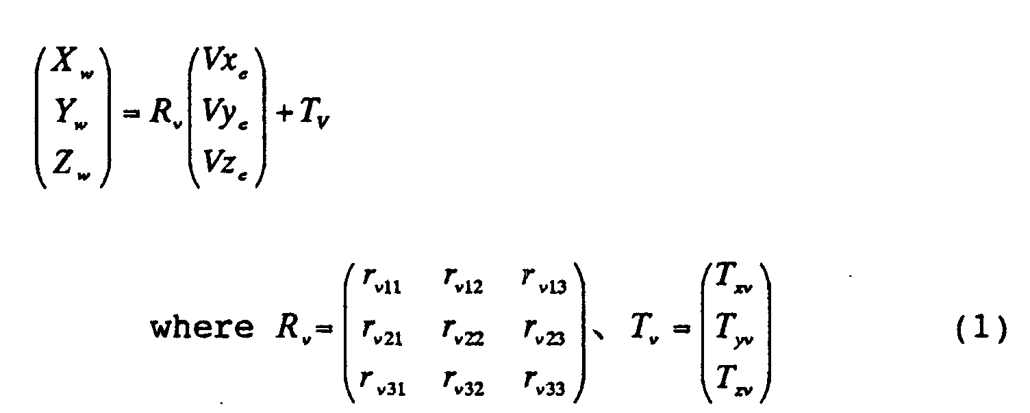


Claims (29)
- An image processing apparatus comprising:wherein the image processing part changes at least one selected from a position, a direction of a line of sight, and a focal length of the virtual point of view in accordance with a running state of the vehicle.an image processing part for receiving images captured by a plurality of cameras shooting surroundings of a vehicle to generate a synthetic image viewed from a virtual point of view from these camera images,
- The image processing apparatus of claim 1,
wherein the image processing part changes at least one selected from a position, a direction of a line of sight, and a focal length of the virtual point of view in accordance with a running speed of the vehicle. - The image processing apparatus of claim 1,
wherein the image processing part changes at least one selected from a position, a direction of a line of sight, and a focal length of the virtual point of view, and controls capturing of an image outside a view range of the changed virtual point of view. - The image processing apparatus of claim 3,
wherein the image processing part controls the capturing of an image outside a view range of the changed virtual point of view by changing a model for image synthesis. - The image processing apparatus of claim 1,
wherein the image processing part changes at least one selected from a position, a direction of a line of sight, and a focal length of the virtual point of view in accordance with a steering angle of the vehicle. - The image processing apparatus of claim 1,
wherein the vehicle includes an object detecting sensor for detecting an obstacle, and
the image processing part changes at least one selected from a position, a direction of a line of sight, and a focal length of the virtual point of view in accordance with results of detection by the object detecting sensor. - The image processing apparatus of claim 1,
wherein the image processing part includes an original mapping table and generates a synthetic image using a mapping table that is cut out from the original mapping table, and
the-image processing part changes at least one selected from a position, a direction of a line of sight, and a focal length of the virtual point of view by changing the mapping table to be cut out from the original mapping table. - An image processing apparatus comprising:wherein the image processing part controls capturing of an image outside a view range of the virtual point of view in accordance with a running state of the vehicle.an image processing part for receiving images captured by a plurality of cameras shooting surroundings of a vehicle to generate a synthetic image viewed from a virtual point of view from these camera images,
- A monitoring system comprising:wherein the image processing part changes at least one selected from a position, a direction of a line of sight, and a focal length of the virtual point of view in accordance with a running state of the vehicle.a plurality of cameras shooting surroundings of a vehicle;an image processing part for receiving images captured by the plurality of cameras to generate a synthetic image viewed from a virtual point of view from these camera images; anda display part for displaying the synthetic image,
- An image processing apparatus comprising:wherein the image processing part generates an image including a first image and a second image as the synthetic image,an image processing part for receiving images captured by a plurality of cameras shooting surroundings of a vehicle to generate a synthetic image from these camera images,the first image being viewed from the virtual point of view,the second image being viewed from a viewpoint that is different from the virtual point of view of the first image in at least one selected from a position, a direction of a line of sight and a focal length, orthe second image being different from the first image in a model.
- The image processing apparatus of claim 10,
wherein the second image is at least one of the camera images. - The image processing apparatus of claim 10,
wherein the first image is a close view image showing the vehicle and surroundings thereof, and
the second image is a distant view image showing an area distant from the surrounding area of the vehicle that is shown by the close view image. - The image processing apparatus of claim 12,
wherein the image processing part arranges the distant view image around the close view image in the synthetic image. - The image processing apparatus of claim 13,
wherein the distant view image is an image having continuity with the close view image. - The image processing apparatus of claim 10, whereinthe first image shows at least a part of the vehicle and at least a part of the surroundings of the vehicle, andthe second image is obtained by enlarging at least a part of the region shown by the first image.
- A monitoring system comprising:wherein the image processing part generates an image including a first image and a second image as the synthetic image,a plurality of cameras shooting surroundings of a vehicle;an image processing part for receiving images captured by the plurality of cameras to generate a synthetic image from these camera images; anda display part for displaying the synthetic image,the first image being viewed from a virtual point of view,the second image being viewed from a viewpoint that is different from the virtual point of view of the first image in at least one selected from a position, a direction of a line of sight and a focal length, orthe second image being different from the first image in a model.
- An image processing apparatus comprising:wherein in the synthetic image, the image processing part displays at least a part of a vehicle region where the vehicle is present, and an attention drawing region for drawing attention in which at least a part of the surroundings of the vehicle is shown.an image processing part for receiving images captured by a plurality of cameras shooting surroundings of a vehicle to generate a synthetic image from these camera images,
- The image processing apparatus of claim 17,
wherein the synthetic image is an image viewed from a virtual point of view that is set above the vehicle. - The image processing apparatus of claim 17,
wherein the image processing part displays an illustration image or an actual image of the vehicle on the vehicle region. - The image processing apparatus of claim 17,
wherein the attention drawing region includes at least a part of a blind spot region around the vehicle that is not shot by any of the cameras. - The image processing apparatus of claim 17,
wherein the attention drawing region corresponds to the blind spot region around the vehicle that is not shot by any of the cameras. - The image processing apparatus of claim 20 or 21,
wherein the image processing part determines a range of a region obtained by combining the blind spot region and the vehicle region, using region data showing a projection region of the vehicle in each camera image. - A monitoring system comprising:wherein in the synthetic image, the image processing part displays at least a part of a vehicle region where the vehicle is present, and an attention drawing region for drawing attention in which at least a part of the surroundings of the vehicle is shown.a plurality of cameras shooting surroundings of a vehicle;an image processing part for receiving images captured by the plurality of cameras to generate a synthetic image from these camera images; anda display part for displaying the synthetic image,
- An image processing apparatus comprising:wherein the image processing part generates the synthetic image, using a mapping table including first mapping data describing a correspondence relationship between pixels of the synthetic image and pixels of the camera images, and second mapping data describing an identifier showing that a pixel of the synthetic image corresponds to pixel data other than the camera images.an image processing part for receiving images captured by a plurality of cameras shooting surroundings of a vehicle to generate a synthetic image from these camera images,
- The image processing apparatus of claim 24,
wherein the pixel data other than the camera images show the vehicle or a blind spot region that is present in at least a part of the surroundings of the vehicle. - The image processing apparatus of claim 24,
wherein the image processing part stores a predetermined image other than the camera images, and
with respect to the pixel of the synthetic image, the second mapping data describe coordinate values corresponding to the pixel in the stored predetermined image. - The image processing apparatus of claim 24,
wherein the second mapping data describe pixel data corresponding to the pixel of the synthetic image. - An image processing apparatus comprising:wherein the image processing part uses mapping data describing a correspondence relationship between pixels of the synthetic image and a plurality of pixel data including one or both of pixel data of the camera images and pixel data other than the camera images, and describing a rate of necessity with respect to each of the pixel data, and weights each pixel data in accordance with the rate of necessity,an image processing part for receiving images captured by a plurality of cameras shooting surroundings of a vehicle to generate a synthetic image from these camera images,
thereby generating the pixel data of the pixels of the synthetic image. - An image processing apparatus comprising:wherein the image processing part includes an original mapping table, cuts out a mapping table describing a correspondence relationship between pixels of the synthetic image and pixels of the camera images, and generates the synthetic image, using the cut-out mapping table.an image processing part for receiving images captured by a plurality of cameras shooting surroundings of a vehicle to generate a synthetic image from these camera images,
Priority Applications (2)
| Application Number | Priority Date | Filing Date | Title |
|---|---|---|---|
| EP11007175A EP2410741A1 (en) | 1999-04-16 | 2000-04-17 | Image processing apparatus and monitoring system |
| EP11007176A EP2410742A1 (en) | 1999-04-16 | 2000-04-17 | Image processing apparatus and monitoring system |
Applications Claiming Priority (3)
| Application Number | Priority Date | Filing Date | Title |
|---|---|---|---|
| JP10994699 | 1999-04-16 | ||
| JP10994699 | 1999-04-16 | ||
| PCT/JP2000/002474 WO2000064175A1 (en) | 1999-04-16 | 2000-04-17 | Image processing device and monitoring system |
Related Child Applications (2)
| Application Number | Title | Priority Date | Filing Date |
|---|---|---|---|
| EP11007176.8 Division-Into | 2011-09-05 | ||
| EP11007175.0 Division-Into | 2011-09-05 |
Publications (3)
| Publication Number | Publication Date |
|---|---|
| EP1179958A1 true EP1179958A1 (en) | 2002-02-13 |
| EP1179958A4 EP1179958A4 (en) | 2009-07-15 |
| EP1179958B1 EP1179958B1 (en) | 2012-08-08 |
Family
ID=14523136
Family Applications (3)
| Application Number | Title | Priority Date | Filing Date |
|---|---|---|---|
| EP00915550A Expired - Lifetime EP1179958B1 (en) | 1999-04-16 | 2000-04-17 | Image processing device and monitoring system |
| EP11007175A Ceased EP2410741A1 (en) | 1999-04-16 | 2000-04-17 | Image processing apparatus and monitoring system |
| EP11007176A Ceased EP2410742A1 (en) | 1999-04-16 | 2000-04-17 | Image processing apparatus and monitoring system |
Family Applications After (2)
| Application Number | Title | Priority Date | Filing Date |
|---|---|---|---|
| EP11007175A Ceased EP2410741A1 (en) | 1999-04-16 | 2000-04-17 | Image processing apparatus and monitoring system |
| EP11007176A Ceased EP2410742A1 (en) | 1999-04-16 | 2000-04-17 | Image processing apparatus and monitoring system |
Country Status (6)
| Country | Link |
|---|---|
| US (1) | US7161616B1 (en) |
| EP (3) | EP1179958B1 (en) |
| KR (1) | KR20010112433A (en) |
| CN (1) | CN100438623C (en) |
| CA (1) | CA2369648A1 (en) |
| WO (1) | WO2000064175A1 (en) |
Cited By (67)
| Publication number | Priority date | Publication date | Assignee | Title |
|---|---|---|---|---|
| EP1261199A3 (en) * | 2001-05-10 | 2004-03-31 | Sharp Kabushiki Kaisha | System and method for perspective projection image creation |
| EP1383332A4 (en) * | 2001-04-24 | 2006-03-29 | Matsushita Electric Industrial Co Ltd | METHOD AND DEVICE FOR DISPLAYING A RECORD IMAGE OF A CAMERA INSTALLED IN A VEHICLE |
| EP1650080A3 (en) * | 2004-10-25 | 2006-05-03 | Nissan Motor Co., Ltd. | Driving support system and method of producing overhead view image |
| EP1641268A4 (en) * | 2004-06-15 | 2006-07-05 | Matsushita Electric Industrial Co Ltd | MONITOR AND MONITOR OF VEHICLE PERIPHERY |
| EP1705063A1 (en) | 2005-03-23 | 2006-09-27 | IEE INTERNATIONAL ELECTRONICS & ENGINEERING S.A. | Vehicle blind spot monitoring system |
| US7139412B2 (en) * | 2001-04-24 | 2006-11-21 | Matsushita Electric Industrial Co., Ltd. | Image synthesis display method and apparatus for vehicle camera |
| EP1725035A1 (en) * | 2005-05-20 | 2006-11-22 | Nissan Motor Co., Ltd. | Image display apparatus and method for a vehicle |
| EP1731366A1 (en) * | 2005-06-07 | 2006-12-13 | Nissan Motor Company Limited | Apparatus and method for displaying images |
| FR2891934A1 (en) * | 2005-10-12 | 2007-04-13 | Valeo Electronique Sys Liaison | DEVICE FOR PROCESSING VIDEO DATA FOR A MOTOR VEHICLE |
| US7277123B1 (en) * | 1998-10-08 | 2007-10-02 | Matsushita Electric Industrial Co., Ltd. | Driving-operation assist and recording medium |
| DE102006031895A1 (en) * | 2006-07-07 | 2008-01-10 | Siemens Ag | Vehicle interval display in traffic shows the leading vehicle in a changing perspective and color according to the length of gap between it and the own vehicle |
| EP2012271A3 (en) * | 2007-07-02 | 2009-05-20 | Nissan Motor Co., Ltd. | Image processing system and method |
| US7554573B2 (en) * | 2002-06-12 | 2009-06-30 | Panasonic Corporation | Drive assisting system |
| WO2008055644A3 (en) * | 2006-11-09 | 2009-07-09 | Bayerische Motoren Werke Ag | Method for the generation of a full image of the surroundings of a motor vehicle |
| CN100566406C (en) * | 2005-02-15 | 2009-12-02 | 松下电器产业株式会社 | Surrounding monitoring device and surrounding monitoring method |
| EP2053860A4 (en) * | 2006-08-18 | 2010-01-20 | Panasonic Corp | ON-BOARD IMAGE PROCESSING DEVICE AND METHOD FOR GENERATING POINT-OF-THE-ART CONVERTING INFORMATION |
| DE102008034606A1 (en) * | 2008-07-25 | 2010-01-28 | Bayerische Motoren Werke Aktiengesellschaft | Method for displaying environment of vehicle on mobile unit, involves wirelessly receiving image signal from vehicle, and generating display image signal on mobile unit through vehicle image signal, where mobile unit has virtual plane |
| WO2010009844A1 (en) * | 2008-07-25 | 2010-01-28 | Bayerische Motoren Werke Aktiengesellschaft | Method for informing a passenger of a vehicle |
| WO2010025792A1 (en) * | 2008-09-08 | 2010-03-11 | Daimler Ag | Method and device for monitoring an environment of a vehicle |
| EP2196773A1 (en) | 2008-12-15 | 2010-06-16 | Robert Bosch GmbH | Control device and method for generating an image display |
| EP1699242A3 (en) * | 2005-03-03 | 2010-07-07 | Nissan Motor Company, Limited | Improvements in or relating to image processing |
| EP2058762A3 (en) * | 2007-11-09 | 2010-09-22 | Alpine Electronics, Inc. | Method and apparatus for generating bird's-eye image |
| EP2234399A1 (en) * | 2009-03-25 | 2010-09-29 | Fujitsu Limited | Image processing method and image processing apparatus |
| DE102010015079A1 (en) * | 2010-04-15 | 2011-10-20 | Valeo Schalter Und Sensoren Gmbh | A method of displaying an image on a display device in a vehicle. Driver assistance system and vehicle |
| DE102010034139A1 (en) | 2010-08-12 | 2012-02-16 | Valeo Schalter Und Sensoren Gmbh | Method for supporting a parking process of a motor vehicle, driver assistance system and motor vehicle |
| WO2012019931A1 (en) * | 2010-08-12 | 2012-02-16 | Valeo Schalter Und Sensoren Gmbh | Method for displaying images on a display device in a motor vehicle, driver assistance system, and motor vehicle |
| DE102010047162A1 (en) * | 2010-09-30 | 2012-04-05 | Valeo Schalter Und Sensoren Gmbh | Method and device for detecting free parking spaces |
| CN102450007A (en) * | 2009-05-29 | 2012-05-09 | 富士通天株式会社 | Image processing apparatus, electronic apparatus, and image processing method |
| DE102010051205A1 (en) | 2010-11-12 | 2012-05-16 | Valeo Schalter Und Sensoren Gmbh | A method of displaying images on a display, camera system and motor vehicle with a camera system |
| US8201199B2 (en) | 2001-06-18 | 2012-06-12 | Panasonic Corporation | Monitoring system |
| EP2481636A1 (en) * | 2011-01-28 | 2012-08-01 | Nxp B.V. | Parking assistance system and method |
| EP1760489B1 (en) * | 2005-08-31 | 2012-08-08 | CLARION Co., Ltd. | Obstacle detector for vehicle |
| EP2487666A2 (en) | 2011-02-10 | 2012-08-15 | Connaught Electronics Ltd. | Method and driver assistance system for displaying images in a motor vehicle |
| EP2502205A2 (en) * | 2009-11-21 | 2012-09-26 | Diehl BGT Defence GmbH & Co.KG | Method for generating a representation of surroundings |
| US8319618B2 (en) | 2008-11-28 | 2012-11-27 | Fujitsu Limited | Image processing apparatus, image processing method, and recording medium |
| CN102804762A (en) * | 2009-06-29 | 2012-11-28 | 松下电器产业株式会社 | Vehicle image display device |
| EP1748654A4 (en) * | 2004-04-27 | 2013-01-02 | Panasonic Corp | VISUALIZATION OF CIRCUMFERENCE OF A VEHICLE |
| EP2280547A4 (en) * | 2008-05-19 | 2013-02-13 | Panasonic Corp | VEHICLE SURROUNDING MONITORING DEVICE AND VEHICLE ENTOURING MONITORING METHOD |
| WO2013037530A1 (en) * | 2011-09-12 | 2013-03-21 | Robert Bosch Gmbh | Driver assistance system for assisting a driver in collision-relevant situations |
| WO2013107548A1 (en) * | 2012-01-19 | 2013-07-25 | Robert Bosch Gmbh | Method and device for visualizing the surroundings of a vehicle |
| EP2285109A4 (en) * | 2008-05-29 | 2013-08-21 | Fujitsu Ltd | VEHICLE IMAGE PROCESSOR AND VEHICLE IMAGE PROCESSING SYSTEM |
| DE102012203092A1 (en) * | 2012-02-29 | 2013-08-29 | Bayerische Motoren Werke Aktiengesellschaft | Method for image processing of image data of image detected by camera, involves determining availability of predetermined object type depending on image data of image, where position is determined with respect to planimetric projection |
| EP2207350B1 (en) * | 2007-10-01 | 2014-01-15 | Nissan Motor Co., Ltd. | Parking assistance device and parking assistance method |
| DE102012014466A1 (en) * | 2012-07-21 | 2014-01-23 | Volkswagen Aktiengesellschaft | Method for representation of scene for vehicle e.g. motor car, involves calculating image which shows scene from view of virtual camera depending on image while displaying image on display of vehicle |
| US8855850B2 (en) | 2007-10-01 | 2014-10-07 | Nissan Motor Co., Ltd. | Parking assistant and parking assisting method |
| US8872919B2 (en) | 2005-02-24 | 2014-10-28 | Aisin Seiki Kabushiki Kaisha | Vehicle surrounding monitoring device |
| US8885045B2 (en) | 2005-08-02 | 2014-11-11 | Nissan Motor Co., Ltd. | Device and method for monitoring vehicle surroundings |
| DE102013010010A1 (en) * | 2013-06-14 | 2014-12-31 | Audi Ag | Method for operating a driver assistance system for maneuvering and / or parking |
| EP2724896A4 (en) * | 2011-06-27 | 2015-05-06 | Clarion Co Ltd | Parking assistance device |
| DE102012102508B4 (en) * | 2011-08-31 | 2015-06-18 | Autoequips Tech Co., Ltd. | Adjustment method and system of a smart vehicle imaging device |
| WO2016162245A1 (en) * | 2015-04-10 | 2016-10-13 | Robert Bosch Gmbh | Method for displaying an area surrounding a vehicle |
| CN106162072A (en) * | 2015-05-11 | 2016-11-23 | 三星电子株式会社 | Viewing method and surrounding copic viewing system around |
| WO2016195792A1 (en) * | 2015-06-02 | 2016-12-08 | Qualcomm Incorporated | Systems and methods for producing a combined view from fisheye cameras |
| EP1453010A3 (en) * | 2003-03-01 | 2017-02-08 | The Boeing Company | Systems and methods for providing enhanced vision imaging with decreased latency |
| EP1453009A3 (en) * | 2003-03-01 | 2017-03-01 | The Boeing Company | Systems and methods for providing enhanced vision imaging |
| WO2017120506A1 (en) | 2016-01-06 | 2017-07-13 | Texas Instruments Incorporated | Three dimensional rendering for surround view using predetermined viewpoint lookup tables |
| EP3306591A3 (en) * | 2016-10-04 | 2018-09-26 | Lg Electronics Inc. | Parking assistance apparatus, vehicle having the same, method of providing automatic parking function |
| WO2019072455A1 (en) * | 2017-10-11 | 2019-04-18 | Robert Bosch Gmbh | METHOD FOR PRESENTING AN ENVIRONMENT OF A VEHICLE |
| EP3462733A4 (en) * | 2016-09-20 | 2019-07-17 | JVC Kenwood Corporation | AERIAL VIEWING VIDEO IMAGE GENERATING DEVICE, AERIAL VIEWING VIDEO IMAGE GENERATING SYSTEM, AERIAL VIEWING VIDEO IMAGE GENERATING METHOD, AND PROGRAM |
| WO2019185097A1 (en) * | 2018-03-26 | 2019-10-03 | Conti Temic Microelectronic Gmbh | Method for monitoring and controlling a remotely-controlled parking or maneuvering operation of a vehicle |
| EP3683102A1 (en) * | 2016-05-05 | 2020-07-22 | Harman International Industries, Incorporated | Systems for driver assistance |
| EP3792868A1 (en) * | 2019-09-12 | 2021-03-17 | Aisin Seiki Kabushiki Kaisha | Image processing device |
| WO2022084054A1 (en) * | 2020-10-21 | 2022-04-28 | Zf Friedrichshafen Ag | Representation of obstacles in an overview image as a function of a steering angle |
| EP3936400A4 (en) * | 2020-05-15 | 2022-06-08 | Guangzhou Xiaopeng Motors Technology Co., Ltd. | METHOD FOR DISPLAYING THREE-DIMENSIONAL PARKING, VEHICLE, AND STORAGE HOLDER |
| WO2022177591A1 (en) * | 2021-02-19 | 2022-08-25 | Western Digital Technologies, Inc. | Surveillance video streams with embedded object data |
| DE102008064951B3 (en) | 2008-07-25 | 2022-11-10 | Bayerische Motoren Werke Aktiengesellschaft | Method for informing an occupant of a vehicle |
| EP4091911A1 (en) * | 2021-05-19 | 2022-11-23 | Guangzhou Xiaopeng Motors Technology Co., Ltd. | Interaction method and apparatus for autonomous driving |
Families Citing this family (400)
| Publication number | Priority date | Publication date | Assignee | Title |
|---|---|---|---|---|
| US6734896B2 (en) * | 2000-04-28 | 2004-05-11 | Matsushita Electric Industrial Co., Ltd. | Image processor and monitoring system |
| JP4156181B2 (en) * | 2000-07-12 | 2008-09-24 | 日産自動車株式会社 | Parking assistance device |
| JP3645196B2 (en) * | 2001-02-09 | 2005-05-11 | 松下電器産業株式会社 | Image synthesizer |
| JP4059309B2 (en) * | 2001-05-07 | 2008-03-12 | 松下電器産業株式会社 | In-vehicle camera image display control method and apparatus |
| JP4860835B2 (en) * | 2001-06-11 | 2012-01-25 | クラリオン株式会社 | Panorama image display method and panorama image display apparatus |
| JP4156214B2 (en) * | 2001-06-13 | 2008-09-24 | 株式会社デンソー | Vehicle periphery image processing apparatus and recording medium |
| JP4713033B2 (en) * | 2001-06-29 | 2011-06-29 | 本田技研工業株式会社 | Vehicle surrounding environment display device |
| JP4786076B2 (en) * | 2001-08-09 | 2011-10-05 | パナソニック株式会社 | Driving support display device |
| DE60207655T2 (en) | 2001-09-07 | 2006-06-08 | Matsushita Electric Industrial Co., Ltd., Kadoma | Device for displaying the environment of a vehicle and system for providing images |
| JP3606853B2 (en) * | 2001-09-07 | 2005-01-05 | 松下電器産業株式会社 | Vehicle ambient condition display device |
| JP2003102002A (en) * | 2001-09-26 | 2003-04-04 | Clarion Co Ltd | Method and apparatus for supervising surrounding of vehicle, and signal processing apparatus |
| JP2003102000A (en) * | 2001-09-26 | 2003-04-04 | Clarion Co Ltd | Vehicle rear part monitoring method, vehicle rear part monitoring device, and signal processor |
| JP2003132349A (en) * | 2001-10-24 | 2003-05-09 | Matsushita Electric Ind Co Ltd | Drawing equipment |
| JP3815291B2 (en) * | 2001-10-24 | 2006-08-30 | 日産自動車株式会社 | Vehicle rear monitoring device |
| JP2003149711A (en) * | 2001-11-08 | 2003-05-21 | Clarion Co Ltd | Vehicle monitor device |
| JP4364471B2 (en) * | 2001-12-28 | 2009-11-18 | 株式会社エクォス・リサーチ | Image processing apparatus for vehicle |
| JP2003209835A (en) * | 2002-01-11 | 2003-07-25 | Clarion Co Ltd | Monitoring device for surrounding of vehicle |
| JP2003219411A (en) * | 2002-01-17 | 2003-07-31 | Clarion Co Ltd | Method and apparatus for monitoring circumference of vehicle |
| JP3916958B2 (en) * | 2002-01-24 | 2007-05-23 | クラリオン株式会社 | Vehicle rear monitoring system and monitoring device |
| JP4021685B2 (en) * | 2002-03-04 | 2007-12-12 | 松下電器産業株式会社 | Image composition converter |
| JP2003264825A (en) * | 2002-03-06 | 2003-09-19 | Nissan Motor Co Ltd | In-vehicle camera video composition display |
| JP3855814B2 (en) * | 2002-03-22 | 2006-12-13 | 日産自動車株式会社 | Image processing apparatus for vehicle |
| US20080292211A1 (en) * | 2002-04-02 | 2008-11-27 | Frantz Robert H | Vehicle exterior examination and search system |
| US7145519B2 (en) | 2002-04-18 | 2006-12-05 | Nissan Motor Co., Ltd. | Image display apparatus, method, and program for automotive vehicle |
| JP2003348574A (en) * | 2002-05-24 | 2003-12-05 | Nissan Motor Co Ltd | Video display device for vehicles |
| DE50302813D1 (en) * | 2002-04-19 | 2006-05-18 | Iee Sarl | SAFETY DEVICE FOR A VEHICLE |
| JP2004007299A (en) * | 2002-06-03 | 2004-01-08 | Nissan Motor Co Ltd | Video display device for vehicles |
| JP4004871B2 (en) * | 2002-06-27 | 2007-11-07 | クラリオン株式会社 | Vehicle surrounding image display method, signal processing device used in the vehicle surrounding image display method, and vehicle surrounding monitoring device equipped with the signal processing device |
| JP2004056683A (en) * | 2002-07-23 | 2004-02-19 | Sumitomo Electric Ind Ltd | Image conversion system, image processing apparatus, and image conversion method |
| JP3982357B2 (en) * | 2002-07-24 | 2007-09-26 | 住友電気工業株式会社 | Image conversion system and image processing apparatus |
| JP2004062103A (en) * | 2002-07-31 | 2004-02-26 | Sony Corp | Image processing apparatus and method, information processing apparatus and method, recording medium, and program |
| DE10238936A1 (en) * | 2002-08-24 | 2004-03-04 | Robert Bosch Gmbh | Device and method for controlling at least one system component of an information technology system |
| JP2004147210A (en) * | 2002-10-25 | 2004-05-20 | Matsushita Electric Ind Co Ltd | Driving support device |
| JP4286556B2 (en) * | 2003-02-24 | 2009-07-01 | 株式会社東芝 | Image display device |
| US7450165B2 (en) * | 2003-05-02 | 2008-11-11 | Grandeye, Ltd. | Multiple-view processing in wide-angle video camera |
| US20100002070A1 (en) | 2004-04-30 | 2010-01-07 | Grandeye Ltd. | Method and System of Simultaneously Displaying Multiple Views for Video Surveillance |
| JP3797343B2 (en) * | 2003-05-12 | 2006-07-19 | 株式会社デンソー | Vehicle periphery display device |
| JP4095491B2 (en) * | 2003-05-19 | 2008-06-04 | 本田技研工業株式会社 | Distance measuring device, distance measuring method, and distance measuring program |
| JP4247066B2 (en) * | 2003-08-01 | 2009-04-02 | 株式会社オートネットワーク技術研究所 | Vehicle periphery visual recognition device |
| JP4479183B2 (en) * | 2003-08-05 | 2010-06-09 | 日産自動車株式会社 | Video presentation device |
| US20050031169A1 (en) * | 2003-08-09 | 2005-02-10 | Alan Shulman | Birds eye view virtual imaging for real time composited wide field of view |
| JP2005167638A (en) * | 2003-12-02 | 2005-06-23 | Sharp Corp | Moving object surrounding monitoring device, moving object, and image conversion method |
| US10140514B1 (en) * | 2004-01-30 | 2018-11-27 | Ip Holdings, Inc. | Capturing and sharing images with mobile device users including for a limited duration of time |
| US11455799B2 (en) | 2004-01-30 | 2022-09-27 | Airspace Reality | Image networks for mobile communication |
| JP4457690B2 (en) * | 2004-02-18 | 2010-04-28 | 日産自動車株式会社 | Driving assistance device |
| JP2005242606A (en) * | 2004-02-26 | 2005-09-08 | Olympus Corp | Image generation system, image generation program and image generation method |
| WO2005088970A1 (en) * | 2004-03-11 | 2005-09-22 | Olympus Corporation | Image generation device, image generation method, and image generation program |
| JP2005269010A (en) * | 2004-03-17 | 2005-09-29 | Olympus Corp | Image creating device, program and method |
| JP2005258792A (en) * | 2004-03-11 | 2005-09-22 | Olympus Corp | Apparatus, method and program for generating image |
| JP2005268847A (en) * | 2004-03-16 | 2005-09-29 | Olympus Corp | Image generating apparatus, image generating method, and image generating program |
| US7679497B1 (en) * | 2004-04-15 | 2010-03-16 | Kenneth Eugene Arant | Recovering legal evidence of unfavorable events or conditions during vehicle operations |
| KR100763234B1 (en) * | 2004-06-11 | 2007-10-04 | 삼성전자주식회사 | System and method for detecting driving conditions |
| JP4552525B2 (en) * | 2004-06-11 | 2010-09-29 | 株式会社エクォス・リサーチ | Image processing apparatus for vehicle |
| JP4374286B2 (en) * | 2004-06-29 | 2009-12-02 | 株式会社アドバネット | Image synthesizer |
| JP2006035980A (en) * | 2004-07-26 | 2006-02-09 | Matsushita Electric Ind Co Ltd | Ride comfort improvement device |
| JP2006050246A (en) * | 2004-08-04 | 2006-02-16 | Auto Network Gijutsu Kenkyusho:Kk | Vehicle periphery visual recognition device |
| JP2006050263A (en) * | 2004-08-04 | 2006-02-16 | Olympus Corp | Image generation method and device |
| US7629995B2 (en) * | 2004-08-06 | 2009-12-08 | Sony Corporation | System and method for correlating camera views |
| WO2006018951A1 (en) * | 2004-08-18 | 2006-02-23 | Olympus Corporation | Image creating method, and image creating apparatus |
| JP4608268B2 (en) * | 2004-08-18 | 2011-01-12 | オリンパス株式会社 | Image generation method and apparatus |
| JP2006072830A (en) * | 2004-09-03 | 2006-03-16 | Aisin Aw Co Ltd | Operation supporting system and operation supporting module |
| JP2006112962A (en) * | 2004-10-15 | 2006-04-27 | Aisin Aw Co Ltd | Method and apparatus for supporting driving operation |
| JP3927571B2 (en) * | 2004-10-25 | 2007-06-13 | 株式会社日立国際電気 | Image display program |
| JP4573242B2 (en) * | 2004-11-09 | 2010-11-04 | アルパイン株式会社 | Driving assistance device |
| US7619658B2 (en) * | 2004-11-15 | 2009-11-17 | Hewlett-Packard Development Company, L.P. | Methods and systems for producing seamless composite images without requiring overlap of source images |
| JP4907883B2 (en) * | 2005-03-09 | 2012-04-04 | 株式会社東芝 | Vehicle periphery image display device and vehicle periphery image display method |
| JP4654736B2 (en) * | 2005-04-04 | 2011-03-23 | 日産自動車株式会社 | Overhead video display device |
| JP2006287826A (en) * | 2005-04-05 | 2006-10-19 | Nissan Motor Co Ltd | Vehicular image generation apparatus and method |
| JP2007088577A (en) * | 2005-09-20 | 2007-04-05 | Denso Corp | Vehicle periphery image processing system |
| JP2007124609A (en) * | 2005-09-28 | 2007-05-17 | Nissan Motor Co Ltd | Vehicle surrounding image providing device |
| US7499586B2 (en) * | 2005-10-04 | 2009-03-03 | Microsoft Corporation | Photographing big things |
| JP4810953B2 (en) * | 2005-10-07 | 2011-11-09 | 日産自動車株式会社 | Blind spot image display device for vehicles |
| JP2007110177A (en) * | 2005-10-10 | 2007-04-26 | Denso Corp | Image processing apparatus and program |
| JP4579145B2 (en) * | 2005-11-30 | 2010-11-10 | アルパイン株式会社 | Vehicle peripheral image display device |
| JP4600999B2 (en) * | 2005-12-26 | 2010-12-22 | アルパイン株式会社 | Vehicle perimeter monitoring device |
| JP4707109B2 (en) * | 2006-03-02 | 2011-06-22 | アルパイン株式会社 | Multi-camera image processing method and apparatus |
| JP2007235842A (en) * | 2006-03-03 | 2007-09-13 | Denso Corp | In-vehicle image display system |
| JP4104631B2 (en) * | 2006-03-27 | 2008-06-18 | 三洋電機株式会社 | Driving support device |
| JP2007274377A (en) * | 2006-03-31 | 2007-10-18 | Denso Corp | Perimeter monitoring device, program |
| JP4656005B2 (en) * | 2006-06-02 | 2011-03-23 | 日産自動車株式会社 | Image processing system and image processing method |
| JP4863791B2 (en) * | 2006-07-05 | 2012-01-25 | アルパイン株式会社 | Vehicle peripheral image generation apparatus and image switching method |
| US20090128630A1 (en) * | 2006-07-06 | 2009-05-21 | Nissan Motor Co., Ltd. | Vehicle image display system and image display method |
| JP4254887B2 (en) * | 2006-07-06 | 2009-04-15 | 日産自動車株式会社 | Image display system for vehicles |
| JP5117003B2 (en) * | 2006-07-11 | 2013-01-09 | 本田技研工業株式会社 | Driving assistance device |
| JP4193886B2 (en) | 2006-07-26 | 2008-12-10 | トヨタ自動車株式会社 | Image display device |
| US20080027985A1 (en) * | 2006-07-31 | 2008-01-31 | Microsoft Corporation | Generating spatial multimedia indices for multimedia corpuses |
| US7712052B2 (en) | 2006-07-31 | 2010-05-04 | Microsoft Corporation | Applications of three-dimensional environments constructed from images |
| WO2008026510A1 (en) * | 2006-08-30 | 2008-03-06 | Toyota Mapmaster Incorporated | Road image creation system |
| JP5159070B2 (en) * | 2006-08-31 | 2013-03-06 | アルパイン株式会社 | Vehicle periphery image display device and display method |
| JP4642723B2 (en) | 2006-09-26 | 2011-03-02 | クラリオン株式会社 | Image generating apparatus and image generating method |
| US8425058B2 (en) * | 2006-11-14 | 2013-04-23 | Alpine Electronics, Inc. | Optical unit, image pickup device using the optical unit, and on-vehicle image display device using the image pickup device |
| US8498497B2 (en) * | 2006-11-17 | 2013-07-30 | Microsoft Corporation | Swarm imaging |
| US9442607B2 (en) * | 2006-12-04 | 2016-09-13 | Smart Technologies Inc. | Interactive input system and method |
| JP4927512B2 (en) * | 2006-12-05 | 2012-05-09 | 株式会社日立製作所 | Image generation device |
| JP4855918B2 (en) * | 2006-12-12 | 2012-01-18 | クラリオン株式会社 | Driving assistance device |
| JP4927514B2 (en) * | 2006-12-12 | 2012-05-09 | クラリオン株式会社 | Driving assistance device |
| JP4859652B2 (en) * | 2006-12-15 | 2012-01-25 | アルパイン株式会社 | Image display device |
| JP4893945B2 (en) * | 2007-02-06 | 2012-03-07 | 株式会社デンソー | Vehicle periphery monitoring device |
| JP4969269B2 (en) * | 2007-02-21 | 2012-07-04 | アルパイン株式会社 | Image processing device |
| GB2447672B (en) | 2007-03-21 | 2011-12-14 | Ford Global Tech Llc | Vehicle manoeuvring aids |
| JP4945315B2 (en) * | 2007-05-23 | 2012-06-06 | 三洋電機株式会社 | Driving support system and vehicle |
| JP2007302238A (en) * | 2007-05-29 | 2007-11-22 | Equos Research Co Ltd | Image processing apparatus for vehicle |
| JP5003946B2 (en) * | 2007-05-30 | 2012-08-22 | アイシン精機株式会社 | Parking assistance device |
| KR100882011B1 (en) * | 2007-07-29 | 2009-02-04 | 주식회사 나노포토닉스 | Method and apparatus for obtaining omnidirectional image using rotationally symmetrical wide angle lens |
| JP4450036B2 (en) * | 2007-09-10 | 2010-04-14 | トヨタ自動車株式会社 | Composite image generating apparatus and program |
| JP4458138B2 (en) * | 2007-09-18 | 2010-04-28 | 株式会社デンソー | Vehicle periphery monitoring device |
| US8218007B2 (en) * | 2007-09-23 | 2012-07-10 | Volkswagen Ag | Camera system for a vehicle and method for controlling a camera system |
| JP5194679B2 (en) * | 2007-09-26 | 2013-05-08 | 日産自動車株式会社 | Vehicle periphery monitoring device and video display method |
| JP5347257B2 (en) * | 2007-09-26 | 2013-11-20 | 日産自動車株式会社 | Vehicle periphery monitoring device and video display method |
| JP4412380B2 (en) * | 2007-10-02 | 2010-02-10 | アイシン・エィ・ダブリュ株式会社 | Driving support device, driving support method, and computer program |
| JP4988499B2 (en) * | 2007-10-10 | 2012-08-01 | 株式会社日本自動車部品総合研究所 | Image generating apparatus and image generating program |
| JP5120880B2 (en) * | 2007-10-15 | 2013-01-16 | アルパイン株式会社 | Image processing apparatus and image processing method |
| DE102007049821A1 (en) | 2007-10-16 | 2009-04-23 | Daimler Ag | Method for calibrating an arrangement with at least one omnidirectional camera and an optical display unit |
| JP5090126B2 (en) * | 2007-10-23 | 2012-12-05 | アルパイン株式会社 | In-vehicle imaging device |
| JP5132249B2 (en) * | 2007-10-23 | 2013-01-30 | アルパイン株式会社 | In-vehicle imaging device |
| JP5053043B2 (en) | 2007-11-09 | 2012-10-17 | アルパイン株式会社 | Vehicle peripheral image generation device and vehicle peripheral image distortion correction method |
| US8694195B2 (en) * | 2007-12-04 | 2014-04-08 | Volkswagen Ag | Motor vehicle having a wheel-view camera and method for controlling a wheel-view camera system |
| KR100882689B1 (en) * | 2007-12-06 | 2009-02-06 | 현대자동차주식회사 | Vehicle rear monitoring system and control method |
| JP5292874B2 (en) * | 2007-12-17 | 2013-09-18 | 富士通株式会社 | VEHICLE IMAGE PROCESSING DEVICE, VEHICLE IMAGE PROCESSING PROGRAM, AND VEHICLE IMAGE PROCESSING METHOD |
| JP5072576B2 (en) * | 2007-12-20 | 2012-11-14 | アルパイン株式会社 | Image display method and image display apparatus |
| JP5064201B2 (en) * | 2007-12-21 | 2012-10-31 | アルパイン株式会社 | Image display system and camera output control method |
| JP4900232B2 (en) * | 2007-12-26 | 2012-03-21 | 日産自動車株式会社 | Vehicle parking assist device and video display method |
| JP5067169B2 (en) * | 2008-01-15 | 2012-11-07 | 日産自動車株式会社 | Vehicle parking assistance apparatus and image display method |
| US8923648B2 (en) * | 2008-01-21 | 2014-12-30 | Denso International America, Inc. | Weighted average image blending based on relative pixel position |
| JP4874280B2 (en) * | 2008-03-19 | 2012-02-15 | 三洋電機株式会社 | Image processing apparatus and method, driving support system, and vehicle |
| JP5222597B2 (en) * | 2008-03-19 | 2013-06-26 | 三洋電機株式会社 | Image processing apparatus and method, driving support system, and vehicle |
| US8395490B2 (en) * | 2008-03-27 | 2013-03-12 | Panasonic Corporation | Blind spot display apparatus |
| DE102008060684B4 (en) * | 2008-03-28 | 2019-05-23 | Volkswagen Ag | Method and device for automatic parking of a motor vehicle |
| JP2008278526A (en) * | 2008-06-16 | 2008-11-13 | Panasonic Corp | Driving support image generation device |
| JP5094597B2 (en) * | 2008-07-02 | 2012-12-12 | 本田技研工業株式会社 | Driving assistance device |
| US8155802B1 (en) * | 2008-07-11 | 2012-04-10 | Lockheed Martin Corporation | Optical flow navigation system |
| JP4661917B2 (en) * | 2008-07-25 | 2011-03-30 | 日産自動車株式会社 | Parking assistance device and parking assistance method |
| KR101394740B1 (en) * | 2008-08-14 | 2014-05-15 | 현대자동차일본기술연구소 | Display device for vehicle and method for controlling the same |
| JP5420216B2 (en) * | 2008-09-16 | 2014-02-19 | 本田技研工業株式会社 | Vehicle perimeter monitoring device |
| JP5112998B2 (en) * | 2008-09-16 | 2013-01-09 | 本田技研工業株式会社 | Vehicle perimeter monitoring device |
| DE102009050368A1 (en) | 2008-10-24 | 2010-05-27 | Magna Electronics Europe Gmbh & Co.Kg | Method for automatically calibrating a virtual camera |
| JP5067632B2 (en) * | 2008-11-28 | 2012-11-07 | アイシン精機株式会社 | Bird's-eye image generator |
| JP5300443B2 (en) | 2008-12-01 | 2013-09-25 | 富士通テン株式会社 | Image processing device |
| JP4876118B2 (en) * | 2008-12-08 | 2012-02-15 | 日立オートモティブシステムズ株式会社 | Three-dimensional object appearance detection device |
| KR100966288B1 (en) * | 2009-01-06 | 2010-06-28 | 주식회사 이미지넥스트 | Around image generating method and apparatus |
| JP2010183170A (en) * | 2009-02-03 | 2010-08-19 | Denso Corp | Display apparatus for vehicle |
| US9126525B2 (en) | 2009-02-27 | 2015-09-08 | Magna Electronics Inc. | Alert system for vehicle |
| JP5068779B2 (en) * | 2009-02-27 | 2012-11-07 | 現代自動車株式会社 | Vehicle surroundings overhead image display apparatus and method |
| JP5195592B2 (en) * | 2009-03-31 | 2013-05-08 | 富士通株式会社 | Video processing device |
| JP5165631B2 (en) | 2009-04-14 | 2013-03-21 | 現代自動車株式会社 | Vehicle surrounding image display system |
| JP5324310B2 (en) | 2009-05-14 | 2013-10-23 | 富士通テン株式会社 | In-vehicle illumination device, image processing device, and image display system |
| US8376595B2 (en) | 2009-05-15 | 2013-02-19 | Magna Electronics, Inc. | Automatic headlamp control |
| JP5986611B2 (en) * | 2009-05-29 | 2016-09-06 | 富士通テン株式会社 | Image processing apparatus, electronic apparatus, and image processing method |
| JP5271154B2 (en) * | 2009-05-29 | 2013-08-21 | 富士通テン株式会社 | Image generating apparatus and image display system |
| JP2009194938A (en) * | 2009-06-01 | 2009-08-27 | Equos Research Co Ltd | Vehicle image processing apparatus |
| US8732592B2 (en) * | 2009-06-08 | 2014-05-20 | Battelle Energy Alliance, Llc | Methods and systems relating to an augmented virtuality environment |
| JP5412979B2 (en) * | 2009-06-19 | 2014-02-12 | コニカミノルタ株式会社 | Peripheral display device |
| JP5226621B2 (en) * | 2009-07-06 | 2013-07-03 | 東芝アルパイン・オートモティブテクノロジー株式会社 | Image display device for vehicle |
| JP5031801B2 (en) * | 2009-07-28 | 2012-09-26 | 日立オートモティブシステムズ株式会社 | In-vehicle image display device |
| CN101990045B (en) * | 2009-07-29 | 2014-02-19 | 鸿富锦精密工业(深圳)有限公司 | Digital image detection system and method |
| JP5500369B2 (en) * | 2009-08-03 | 2014-05-21 | アイシン精機株式会社 | Vehicle peripheral image generation device |
| JP5436086B2 (en) * | 2009-08-03 | 2014-03-05 | アルパイン株式会社 | Vehicle periphery image display device and vehicle periphery image display method |
| US8988525B2 (en) * | 2009-08-27 | 2015-03-24 | Robert Bosch Gmbh | System and method for providing guidance information to a driver of a vehicle |
| US8310523B2 (en) * | 2009-08-27 | 2012-11-13 | Sony Corporation | Plug-in to enable CAD software not having greater than 180 degree capability to present image from camera of more than 180 degrees |
| JP2011091527A (en) * | 2009-10-21 | 2011-05-06 | Panasonic Corp | Video conversion device and imaging apparatus |
| JP2011135253A (en) * | 2009-12-24 | 2011-07-07 | Fujitsu Ten Ltd | Image processor, image processing system and image processing method |
| TWI417639B (en) * | 2009-12-30 | 2013-12-01 | Ind Tech Res Inst | Method and system for forming surrounding seamless bird-view image |
| TWI392366B (en) * | 2009-12-31 | 2013-04-01 | Ind Tech Res Inst | Method and system for generating surrounding seamless bird-view image with distance interface |
| JP5521599B2 (en) * | 2010-02-08 | 2014-06-18 | 富士通株式会社 | Video composition apparatus and video composition program |
| US8456518B2 (en) * | 2010-03-31 | 2013-06-04 | James Cameron & Vincent Pace | Stereoscopic camera with automatic obstruction removal |
| JP5090496B2 (en) * | 2010-04-12 | 2012-12-05 | 住友重機械工業株式会社 | Image generating apparatus and operation support system |
| JP5645450B2 (en) * | 2010-04-16 | 2014-12-24 | キヤノン株式会社 | Image processing apparatus and method |
| US8594972B2 (en) * | 2010-06-11 | 2013-11-26 | The Johns Hopkins University | System and method for tomographic retrieval of parameter profile from traveling path |
| CN102986210B (en) | 2010-07-14 | 2014-05-14 | 三菱电机株式会社 | image synthesis device |
| DE102010033003A1 (en) | 2010-07-31 | 2011-03-17 | Daimler Ag | Guide for motor vehicle, has optical display comprising lighting element for producing lighting points at place of reference point and unit for producing light-dark contrast or color difference at place of reference point |
| CN102381252A (en) * | 2010-09-02 | 2012-03-21 | 张士达 | Automobile 360-degree visual-angle monitoring system and automobile using the same |
| DE102010040803A1 (en) * | 2010-09-15 | 2012-03-15 | Continental Teves Ag & Co. Ohg | Visual driver information and warning system for a driver of a motor vehicle |
| JP5251947B2 (en) * | 2010-09-17 | 2013-07-31 | 日産自動車株式会社 | Image display device for vehicle |
| JP5454934B2 (en) | 2010-09-21 | 2014-03-26 | アイシン精機株式会社 | Driving assistance device |
| WO2012061567A1 (en) | 2010-11-04 | 2012-05-10 | Magna Electronics Inc. | Vehicular camera system with reduced number of pins and conduits |
| WO2012068331A1 (en) | 2010-11-19 | 2012-05-24 | Magna Electronics Inc. | Lane keeping system and lane centering system |
| JP5516992B2 (en) | 2010-11-30 | 2014-06-11 | アイシン精機株式会社 | Parking position adjustment device |
| US8983717B2 (en) | 2010-12-21 | 2015-03-17 | Ford Global Technologies, Llc | Vehicle camera system operable in off-road mode and method |
| US9264672B2 (en) | 2010-12-22 | 2016-02-16 | Magna Mirrors Of America, Inc. | Vision display system for vehicle |
| JP2012169883A (en) * | 2011-02-15 | 2012-09-06 | Panasonic Corp | Driving support device and vehicle |
| JP5699679B2 (en) * | 2011-02-24 | 2015-04-15 | 富士通セミコンダクター株式会社 | Image processing apparatus, image processing system, and image processing method |
| WO2012116043A1 (en) | 2011-02-25 | 2012-08-30 | Magna Electronics Inc. | Vehicular camera with aligned housing members and electrical connection between aligned housing members |
| US8768575B2 (en) * | 2011-03-18 | 2014-07-01 | Toyota Jidosha Kabushiki Kaisha | Vehicle periphery monitoring device |
| TW201239807A (en) * | 2011-03-24 | 2012-10-01 | Hon Hai Prec Ind Co Ltd | Image capture device and method for monitoring specified scene using the image capture device |
| CN102694968B (en) * | 2011-03-25 | 2016-03-30 | 中山市云创知识产权服务有限公司 | Camera device and environment monitoring method thereof |
| US9194943B2 (en) | 2011-04-12 | 2015-11-24 | Magna Electronics Inc. | Step filter for estimating distance in a time-of-flight ranging system |
| EP2511137B1 (en) * | 2011-04-14 | 2019-03-27 | Harman Becker Automotive Systems GmbH | Vehicle Surround View System |
| US9555832B2 (en) | 2011-04-19 | 2017-01-31 | Ford Global Technologies, Llc | Display system utilizing vehicle and trailer dynamics |
| US9969428B2 (en) | 2011-04-19 | 2018-05-15 | Ford Global Technologies, Llc | Trailer backup assist system with waypoint selection |
| US9683848B2 (en) | 2011-04-19 | 2017-06-20 | Ford Global Technologies, Llc | System for determining hitch angle |
| US9500497B2 (en) | 2011-04-19 | 2016-11-22 | Ford Global Technologies, Llc | System and method of inputting an intended backing path |
| US9926008B2 (en) | 2011-04-19 | 2018-03-27 | Ford Global Technologies, Llc | Trailer backup assist system with waypoint selection |
| US9374562B2 (en) | 2011-04-19 | 2016-06-21 | Ford Global Technologies, Llc | System and method for calculating a horizontal camera to target distance |
| US9506774B2 (en) * | 2011-04-19 | 2016-11-29 | Ford Global Technologies, Llc | Method of inputting a path for a vehicle and trailer |
| US9723274B2 (en) | 2011-04-19 | 2017-08-01 | Ford Global Technologies, Llc | System and method for adjusting an image capture setting |
| US9854209B2 (en) | 2011-04-19 | 2017-12-26 | Ford Global Technologies, Llc | Display system utilizing vehicle and trailer dynamics |
| US20160129883A1 (en) * | 2011-04-22 | 2016-05-12 | Angel A. Penilla | Contact detect feature of a vehicle and notifications to enable live views of vehicle |
| US9547795B2 (en) | 2011-04-25 | 2017-01-17 | Magna Electronics Inc. | Image processing method for detecting objects using relative motion |
| JP2012244196A (en) * | 2011-05-13 | 2012-12-10 | Sony Corp | Image processing apparatus and method |
| JP5858650B2 (en) * | 2011-06-08 | 2016-02-10 | 富士通テン株式会社 | Image generation apparatus, image display system, and image generation method |
| JP5853457B2 (en) * | 2011-07-20 | 2016-02-09 | アイシン精機株式会社 | Vehicle perimeter monitoring system |
| EP2554434B1 (en) * | 2011-08-05 | 2014-05-21 | Harman Becker Automotive Systems GmbH | Vehicle surround view system |
| CN107097721B (en) | 2011-08-26 | 2020-03-06 | 松下知识产权经营株式会社 | Driving support device |
| WO2013043661A1 (en) | 2011-09-21 | 2013-03-28 | Magna Electronics, Inc. | Vehicle vision system using image data transmission and power supply via a coaxial cable |
| US9681062B2 (en) | 2011-09-26 | 2017-06-13 | Magna Electronics Inc. | Vehicle camera image quality improvement in poor visibility conditions by contrast amplification |
| JP5447490B2 (en) * | 2011-11-18 | 2014-03-19 | アイシン精機株式会社 | Vehicle monitoring device |
| US9264673B2 (en) | 2011-11-20 | 2016-02-16 | Magna Electronics, Inc. | Vehicle vision system with enhanced functionality |
| US10071687B2 (en) | 2011-11-28 | 2018-09-11 | Magna Electronics Inc. | Vision system for vehicle |
| KR101265711B1 (en) * | 2011-11-30 | 2013-05-20 | 주식회사 이미지넥스트 | 3d vehicle around view generating method and apparatus |
| KR101239740B1 (en) * | 2011-12-08 | 2013-03-18 | 아진산업(주) | An apparatus for generating around view image of vehicle using polygon mapping and multi look-up table |
| WO2013086249A2 (en) | 2011-12-09 | 2013-06-13 | Magna Electronics, Inc. | Vehicle vision system with customized display |
| JP5803646B2 (en) * | 2011-12-15 | 2015-11-04 | アイシン精機株式会社 | Vehicle periphery monitoring device |
| US9697735B2 (en) | 2011-12-15 | 2017-07-04 | Panasonic Intellectual Property Management Co., Ltd. | Drive assistance device |
| US20150022664A1 (en) * | 2012-01-20 | 2015-01-22 | Magna Electronics Inc. | Vehicle vision system with positionable virtual viewpoint |
| EP2620917B1 (en) * | 2012-01-30 | 2019-08-28 | Harman Becker Automotive Systems GmbH | Viewing system and method for displaying an environment of a vehicle |
| WO2013126715A2 (en) * | 2012-02-22 | 2013-08-29 | Magna Electronics, Inc. | Vehicle camera system with image manipulation |
| US8694224B2 (en) | 2012-03-01 | 2014-04-08 | Magna Electronics Inc. | Vehicle yaw rate correction |
| US9565342B2 (en) | 2012-03-06 | 2017-02-07 | Magna Electronics Inc. | Vehicle camera with tolerance compensating connector |
| US10609335B2 (en) | 2012-03-23 | 2020-03-31 | Magna Electronics Inc. | Vehicle vision system with accelerated object confirmation |
| WO2013148675A1 (en) * | 2012-03-26 | 2013-10-03 | Robert Bosch Gmbh | Multi-surface model-based tracking |
| US9598836B2 (en) | 2012-03-29 | 2017-03-21 | Harnischfeger Technologies, Inc. | Overhead view system for a shovel |
| US9751465B2 (en) | 2012-04-16 | 2017-09-05 | Magna Electronics Inc. | Vehicle vision system with reduced image color data processing by use of dithering |
| US10089537B2 (en) | 2012-05-18 | 2018-10-02 | Magna Electronics Inc. | Vehicle vision system with front and rear camera integration |
| KR101376211B1 (en) * | 2012-06-01 | 2014-03-21 | 현대모비스 주식회사 | Image composing apparatus of around view monitor system for changing view mode easily and method thereof |
| JP5904026B2 (en) * | 2012-06-15 | 2016-04-13 | 東芝ライテック株式会社 | Lighting control system |
| KR101376210B1 (en) * | 2012-08-06 | 2014-03-21 | 현대모비스 주식회사 | Around View Monitor System and Monitoring Method |
| US9340227B2 (en) | 2012-08-14 | 2016-05-17 | Magna Electronics Inc. | Vehicle lane keep assist system |
| JP5911775B2 (en) * | 2012-08-21 | 2016-04-27 | 富士通テン株式会社 | Image generation apparatus, image display system, and image generation method |
| DE102013217430B4 (en) | 2012-09-04 | 2026-02-26 | Magna Electronics, Inc. | Driver assistance system for a motor vehicle |
| JP5643272B2 (en) * | 2012-09-21 | 2014-12-17 | 株式会社小松製作所 | Work vehicle periphery monitoring system and work vehicle |
| JP6079131B2 (en) * | 2012-10-25 | 2017-02-15 | 富士通株式会社 | Image processing apparatus, method, and program |
| KR101417383B1 (en) * | 2012-10-31 | 2014-07-08 | 현대자동차주식회사 | Apparatus and method for image control of room-mirror |
| KR101896715B1 (en) * | 2012-10-31 | 2018-09-07 | 현대자동차주식회사 | Apparatus and method for position tracking of peripheral vehicle |
| TWI505203B (en) | 2012-11-02 | 2015-10-21 | Avisonic Technology Corp | Image processing method and image processing apparatus for generating vehicular image |
| KR101417399B1 (en) * | 2012-11-09 | 2014-07-08 | 현대자동차주식회사 | Apparatus and method for parking position display of vehicle |
| TWI517992B (en) * | 2012-11-13 | 2016-01-21 | 義晶科技股份有限公司 | Vehicular image system, and display control method for vehicular image thereof |
| TWI535587B (en) * | 2012-11-14 | 2016-06-01 | 義晶科技股份有限公司 | Method for controlling display of vehicular image by touch panel and vehicular image system thereof |
| US9743002B2 (en) | 2012-11-19 | 2017-08-22 | Magna Electronics Inc. | Vehicle vision system with enhanced display functions |
| US9307640B2 (en) | 2012-11-19 | 2016-04-05 | Magna Electronics Inc. | PCB pad for imager of vehicle vision system |
| US9090234B2 (en) | 2012-11-19 | 2015-07-28 | Magna Electronics Inc. | Braking control system for vehicle |
| US10025994B2 (en) | 2012-12-04 | 2018-07-17 | Magna Electronics Inc. | Vehicle vision system utilizing corner detection |
| US9481301B2 (en) | 2012-12-05 | 2016-11-01 | Magna Electronics Inc. | Vehicle vision system utilizing camera synchronization |
| US20140168415A1 (en) | 2012-12-07 | 2014-06-19 | Magna Electronics Inc. | Vehicle vision system with micro lens array |
| KR101406232B1 (en) * | 2012-12-20 | 2014-06-12 | 현대오트론 주식회사 | Apparatus and method for door open warning |
| JP6143469B2 (en) * | 2013-01-17 | 2017-06-07 | キヤノン株式会社 | Information processing apparatus, information processing method, and program |
| JP5708669B2 (en) * | 2013-01-18 | 2015-04-30 | 株式会社デンソー | Vehicle display device |
| US20140218529A1 (en) | 2013-02-04 | 2014-08-07 | Magna Electronics Inc. | Vehicle data recording system |
| US9592851B2 (en) | 2013-02-04 | 2017-03-14 | Ford Global Technologies, Llc | Control modes for a trailer backup assist system |
| US9092986B2 (en) | 2013-02-04 | 2015-07-28 | Magna Electronics Inc. | Vehicular vision system |
| US9511799B2 (en) | 2013-02-04 | 2016-12-06 | Ford Global Technologies, Llc | Object avoidance for a trailer backup assist system |
| CN104885448B (en) * | 2013-02-21 | 2018-04-06 | 本田技研工业株式会社 | Driving assistance device and image processing program |
| US10057544B2 (en) | 2013-03-04 | 2018-08-21 | Magna Electronics Inc. | Vehicle vision system camera with integrated physical layer components |
| US10027930B2 (en) | 2013-03-29 | 2018-07-17 | Magna Electronics Inc. | Spectral filtering for vehicular driver assistance systems |
| EP2983139A4 (en) * | 2013-04-04 | 2016-12-28 | Sony Corp | IMAGE PROCESSING DEVICE, IMAGE PROCESSING METHOD, AND PROGRAM |
| US9327693B2 (en) | 2013-04-10 | 2016-05-03 | Magna Electronics Inc. | Rear collision avoidance system for vehicle |
| US10232797B2 (en) | 2013-04-29 | 2019-03-19 | Magna Electronics Inc. | Rear vision system for vehicle with dual purpose signal lines |
| US10029621B2 (en) | 2013-05-16 | 2018-07-24 | Ford Global Technologies, Llc | Rear view camera system using rear view mirror location |
| US9834143B2 (en) * | 2013-05-23 | 2017-12-05 | GM Global Technology Operations LLC | Enhanced perspective view generation in a front curb viewing system |
| US10567705B2 (en) | 2013-06-10 | 2020-02-18 | Magna Electronics Inc. | Coaxial cable with bidirectional data transmission |
| US9260095B2 (en) | 2013-06-19 | 2016-02-16 | Magna Electronics Inc. | Vehicle vision system with collision mitigation |
| US20140375476A1 (en) | 2013-06-24 | 2014-12-25 | Magna Electronics Inc. | Vehicle alert system |
| US9619716B2 (en) | 2013-08-12 | 2017-04-11 | Magna Electronics Inc. | Vehicle vision system with image classification |
| US10326969B2 (en) | 2013-08-12 | 2019-06-18 | Magna Electronics Inc. | Vehicle vision system with reduction of temporal noise in images |
| KR20150019192A (en) * | 2013-08-13 | 2015-02-25 | 현대모비스 주식회사 | Apparatus and method for composition image for avm system |
| KR102045088B1 (en) * | 2013-08-13 | 2019-11-14 | 현대모비스 주식회사 | Image displaying Method and Apparatus therefor |
| KR101491324B1 (en) * | 2013-10-08 | 2015-02-06 | 현대자동차주식회사 | Apparatus for Taking of Image for Vehicle |
| US9881220B2 (en) | 2013-10-25 | 2018-01-30 | Magna Electronics Inc. | Vehicle vision system utilizing communication system |
| US9499139B2 (en) | 2013-12-05 | 2016-11-22 | Magna Electronics Inc. | Vehicle monitoring system |
| CN104691415B (en) * | 2013-12-07 | 2017-02-01 | 惠州市德赛西威汽车电子股份有限公司 | Panoramic auxiliary parking device |
| US9988047B2 (en) | 2013-12-12 | 2018-06-05 | Magna Electronics Inc. | Vehicle control system with traffic driving control |
| EP3085074B1 (en) * | 2013-12-19 | 2020-02-26 | Intel Corporation | Bowl-shaped imaging system |
| DE102015202846B4 (en) | 2014-02-19 | 2020-06-25 | Magna Electronics, Inc. | Vehicle vision system with display |
| US9688199B2 (en) | 2014-03-04 | 2017-06-27 | Magna Electronics Inc. | Vehicle alert system utilizing communication system |
| JP6741582B2 (en) * | 2014-03-19 | 2020-08-19 | コンティ テミック マイクロエレクトロニック ゲゼルシャフト ミット ベシュレンクテル ハフツングConti Temic microelectronic GmbH | Method for storing camera image data in vehicle accident data memory |
| US9623878B2 (en) | 2014-04-02 | 2017-04-18 | Magna Electronics Inc. | Personalized driver assistance system for vehicle |
| US9487235B2 (en) | 2014-04-10 | 2016-11-08 | Magna Electronics Inc. | Vehicle control system with adaptive wheel angle correction |
| DE102014107235A1 (en) * | 2014-05-22 | 2015-11-26 | Dr. Ing. H.C. F. Porsche Aktiengesellschaft | A method of displaying a vehicle environment on a display device; a display device; a system of a plurality of image capture units and a display device; a computer program |
| US9971947B2 (en) | 2014-07-31 | 2018-05-15 | Magna Electronics Inc. | Vehicle vision system with camera power control |
| US9729636B2 (en) | 2014-08-01 | 2017-08-08 | Magna Electronics Inc. | Smart road system for vehicles |
| US9925980B2 (en) | 2014-09-17 | 2018-03-27 | Magna Electronics Inc. | Vehicle collision avoidance system with enhanced pedestrian avoidance |
| US10442355B2 (en) | 2014-09-17 | 2019-10-15 | Intel Corporation | Object visualization in bowl-shaped imaging systems |
| US10356337B2 (en) | 2014-10-07 | 2019-07-16 | Magna Electronics Inc. | Vehicle vision system with gray level transition sensitive pixels |
| CN104442569B (en) * | 2014-11-14 | 2016-11-02 | 东风汽车有限公司 | Automobile monitoring image generation method and system |
| US9930296B2 (en) * | 2014-11-18 | 2018-03-27 | Denso Corporation | Image switching device for vehicle |
| US9522677B2 (en) | 2014-12-05 | 2016-12-20 | Ford Global Technologies, Llc | Mitigation of input device failure and mode management |
| US9533683B2 (en) | 2014-12-05 | 2017-01-03 | Ford Global Technologies, Llc | Sensor failure mitigation system and mode management |
| DE102014225883A1 (en) * | 2014-12-15 | 2016-06-16 | Robert Bosch Gmbh | A camera system and method for visualizing at least one vehicle surrounding area of a vehicle environment of a vehicle |
| US9740945B2 (en) | 2015-01-14 | 2017-08-22 | Magna Electronics Inc. | Driver assistance system for vehicle |
| US10032369B2 (en) | 2015-01-15 | 2018-07-24 | Magna Electronics Inc. | Vehicle vision system with traffic monitoring and alert |
| US9607242B2 (en) | 2015-01-16 | 2017-03-28 | Ford Global Technologies, Llc | Target monitoring system with lens cleaning device |
| JP6548900B2 (en) * | 2015-01-20 | 2019-07-24 | 株式会社デンソーテン | Image generation apparatus, image generation method and program |
| US9764744B2 (en) | 2015-02-25 | 2017-09-19 | Magna Electronics Inc. | Vehicle yaw rate estimation system |
| US10286855B2 (en) | 2015-03-23 | 2019-05-14 | Magna Electronics Inc. | Vehicle vision system with video compression |
| US10298818B2 (en) | 2015-03-23 | 2019-05-21 | Magna Electronics Inc. | Vehicle camera with enhanced imager and PCB assembly |
| JP2016201585A (en) * | 2015-04-07 | 2016-12-01 | 株式会社ソシオネクスト | Image processing apparatus and image processing apparatus control method |
| JP5959684B2 (en) * | 2015-04-16 | 2016-08-02 | ルネサスエレクトロニクス株式会社 | Image conversion system |
| US10819943B2 (en) | 2015-05-07 | 2020-10-27 | Magna Electronics Inc. | Vehicle vision system with incident recording function |
| CN104859542B (en) * | 2015-05-26 | 2017-06-27 | 寅家电子科技(上海)有限公司 | Vehicle-mounted monitoring system and vehicle-mounted monitoring processing method |
| JP6582557B2 (en) * | 2015-05-28 | 2019-10-02 | 株式会社ソシオネクスト | Drawing apparatus, drawing method, and drawing program |
| US10486599B2 (en) | 2015-07-17 | 2019-11-26 | Magna Mirrors Of America, Inc. | Rearview vision system for vehicle |
| EP3337166B1 (en) | 2015-08-10 | 2020-01-01 | JVC Kenwood Corporation | Vehicular display apparatus and vehicular display method |
| KR101860610B1 (en) * | 2015-08-20 | 2018-07-02 | 엘지전자 주식회사 | Display Apparatus and Vehicle Having The Same |
| US9896130B2 (en) | 2015-09-11 | 2018-02-20 | Ford Global Technologies, Llc | Guidance system for a vehicle reversing a trailer along an intended backing path |
| JP6555056B2 (en) * | 2015-09-30 | 2019-08-07 | アイシン精機株式会社 | Perimeter monitoring device |
| JP6521086B2 (en) * | 2015-10-08 | 2019-05-29 | 日産自動車株式会社 | Display support apparatus and display support method |
| CN108140318A (en) * | 2015-10-22 | 2018-06-08 | 日产自动车株式会社 | Display control method and display control unit |
| US10875403B2 (en) | 2015-10-27 | 2020-12-29 | Magna Electronics Inc. | Vehicle vision system with enhanced night vision |
| US9836060B2 (en) | 2015-10-28 | 2017-12-05 | Ford Global Technologies, Llc | Trailer backup assist system with target management |
| US20170124881A1 (en) * | 2015-10-28 | 2017-05-04 | Velvac Incorporated | Blind zone warning for semi-trailer |
| US9902322B2 (en) | 2015-10-30 | 2018-02-27 | Bendix Commercial Vehicle Systems Llc | Filling in surround view areas blocked by mirrors or other vehicle parts |
| US20170132476A1 (en) * | 2015-11-08 | 2017-05-11 | Otobrite Electronics Inc. | Vehicle Imaging System |
| JP6091586B1 (en) * | 2015-11-12 | 2017-03-08 | 三菱電機株式会社 | VEHICLE IMAGE PROCESSING DEVICE AND VEHICLE IMAGE PROCESSING SYSTEM |
| WO2017086057A1 (en) * | 2015-11-17 | 2017-05-26 | 株式会社Jvcケンウッド | Display device for vehicles and display method for vehicles |
| JP6699427B2 (en) * | 2015-11-17 | 2020-05-27 | 株式会社Jvcケンウッド | Vehicle display device and vehicle display method |
| US10144419B2 (en) | 2015-11-23 | 2018-12-04 | Magna Electronics Inc. | Vehicle dynamic control system for emergency handling |
| JP6623729B2 (en) * | 2015-12-04 | 2019-12-25 | 株式会社ソシオネクスト | Ranging systems, moving objects and parts |
| US11027654B2 (en) | 2015-12-04 | 2021-06-08 | Magna Electronics Inc. | Vehicle vision system with compressed video transfer via DSRC link |
| US11285878B2 (en) | 2015-12-17 | 2022-03-29 | Magna Electronics Inc. | Vehicle vision system with camera line power filter |
| JP6644256B2 (en) * | 2015-12-22 | 2020-02-12 | 株式会社Jvcケンウッド | Overhead video generation device, overhead video generation system, overhead video generation method and program |
| JP2017143340A (en) * | 2016-02-08 | 2017-08-17 | 株式会社デンソー | Information processing apparatus and program |
| US10132971B2 (en) | 2016-03-04 | 2018-11-20 | Magna Electronics Inc. | Vehicle camera with multiple spectral filters |
| US10055651B2 (en) | 2016-03-08 | 2018-08-21 | Magna Electronics Inc. | Vehicle vision system with enhanced lane tracking |
| JP6477562B2 (en) | 2016-03-18 | 2019-03-06 | 株式会社デンソー | Information processing device |
| TWI608448B (en) * | 2016-03-25 | 2017-12-11 | 晶睿通訊股份有限公司 | Setting method of a counting flow path, image monitoring system with setting function of the counting flow path and related computer-readable media |
| JP6313355B2 (en) | 2016-03-31 | 2018-04-18 | 株式会社Subaru | Vehicle perimeter monitoring device |
| JP6360850B2 (en) * | 2016-04-25 | 2018-07-18 | 本田技研工業株式会社 | Image display device |
| US10112646B2 (en) | 2016-05-05 | 2018-10-30 | Ford Global Technologies, Llc | Turn recovery human machine interface for trailer backup assist |
| JP6723820B2 (en) * | 2016-05-18 | 2020-07-15 | 株式会社デンソーテン | Image generation apparatus, image display system, and image display method |
| US10607417B2 (en) * | 2016-06-08 | 2020-03-31 | Sony Interactive Entertainment Inc. | Image generating apparatus and image generating method |
| WO2017212720A1 (en) | 2016-06-08 | 2017-12-14 | 株式会社ソニー・インタラクティブエンタテインメント | Image generation device and image generation method |
| JP6551316B2 (en) * | 2016-06-10 | 2019-07-31 | 京セラドキュメントソリューションズ株式会社 | Image reading apparatus and image forming apparatus |
| KR102519592B1 (en) * | 2016-09-02 | 2023-04-10 | 삼성전자주식회사 | Display apparatus and controlling method thereof |
| US10380439B2 (en) | 2016-09-06 | 2019-08-13 | Magna Electronics Inc. | Vehicle sensing system for detecting turn signal indicators |
| DE102016217488A1 (en) * | 2016-09-14 | 2018-03-15 | Robert Bosch Gmbh | A method of providing a rearview view of a vehicle environment of a vehicle |
| EP3315907B1 (en) * | 2016-10-27 | 2025-03-26 | Leica Geosystems AG | Verfahren zur visuellen darstellung von scandaten |
| JP6855254B2 (en) * | 2017-01-12 | 2021-04-07 | 株式会社デンソーテン | Image processing device, image processing system, and image processing method |
| EP3584120B1 (en) * | 2017-02-17 | 2021-04-14 | Sumitomo Heavy Industries, Ltd. | Work machine surroundings monitoring system |
| JP6724821B2 (en) * | 2017-02-28 | 2020-07-15 | 株式会社Jvcケンウッド | Overhead video generation device, overhead video generation system, overhead video generation method and program |
| EP3537714B1 (en) | 2017-02-28 | 2021-08-25 | JVC Kenwood Corporation | Bird's-eye-view video image generation device, bird's-eye-view video image generation system, bird's-eye-view video image generation method, and program |
| DE102017003399A1 (en) * | 2017-04-07 | 2018-10-11 | Man Truck & Bus Ag | Technology for issuing vehicle messages |
| EP3392801A1 (en) * | 2017-04-21 | 2018-10-24 | Harman International Industries, Incorporated | Systems and methods for driver assistance |
| CN107176101A (en) * | 2017-05-24 | 2017-09-19 | 维森软件技术(上海)有限公司 | Synchronous display method |
| DE102017117094A1 (en) | 2017-07-28 | 2019-01-31 | Connaught Electronics Ltd. | Customizable representation of an environment of a motor vehicle by a driver assistance device |
| JP7039879B2 (en) * | 2017-08-03 | 2022-03-23 | 株式会社アイシン | Display control device |
| JP7056034B2 (en) * | 2017-08-14 | 2022-04-19 | 株式会社アイシン | Peripheral monitoring device |
| JP2019034692A (en) * | 2017-08-21 | 2019-03-07 | 株式会社東海理化電機製作所 | Vehicle visual recognition device |
| US11004226B2 (en) * | 2017-09-07 | 2021-05-11 | Sony Corporation | Image processing device, image processing method, and image display system for grasping a distance from an obstacle with a smaller visual line shift |
| JP7013751B2 (en) * | 2017-09-15 | 2022-02-01 | 株式会社アイシン | Image processing equipment |
| JP7091624B2 (en) | 2017-09-15 | 2022-06-28 | 株式会社アイシン | Image processing equipment |
| US10933798B2 (en) | 2017-09-22 | 2021-03-02 | Magna Electronics Inc. | Vehicle lighting control system with fog detection |
| US10583779B2 (en) * | 2017-10-02 | 2020-03-10 | Magna Electronics Inc. | Parking assist system using backup camera |
| US10744941B2 (en) | 2017-10-12 | 2020-08-18 | Magna Electronics Inc. | Vehicle vision system with bird's eye view display |
| US10580299B2 (en) * | 2017-10-13 | 2020-03-03 | Waymo Llc | Lane change notification |
| EP3480779B1 (en) * | 2017-11-01 | 2026-01-07 | Volvo Car Corporation | Method and system for handling images |
| US10682966B2 (en) | 2017-11-16 | 2020-06-16 | Magna Electronics Inc. | Vehicle light/display control system using camera |
| JP7106846B2 (en) | 2017-11-24 | 2022-07-27 | 株式会社アイシン | Perimeter monitoring device |
| JP2019103067A (en) * | 2017-12-06 | 2019-06-24 | キヤノン株式会社 | Information processing device, storage device, image processing device, image processing system, control method, and program |
| JP6939494B2 (en) * | 2017-12-11 | 2021-09-22 | トヨタ自動車株式会社 | Image display device |
| JP7023696B2 (en) * | 2017-12-12 | 2022-02-22 | キヤノン株式会社 | Information processing equipment, information processing methods and programs |
| JP6835004B2 (en) * | 2018-02-09 | 2021-02-24 | 株式会社デンソー | Image generator |
| US11417107B2 (en) | 2018-02-19 | 2022-08-16 | Magna Electronics Inc. | Stationary vision system at vehicle roadway |
| CN110406472A (en) * | 2018-04-27 | 2019-11-05 | 华创车电技术中心股份有限公司 | Parking assistance system and parking assistance method |
| JP7021001B2 (en) * | 2018-05-25 | 2022-02-16 | アルパイン株式会社 | Image processing device and image processing method |
| DE102018210812A1 (en) | 2018-06-30 | 2020-01-02 | Robert Bosch Gmbh | Method for a sensor- and memory-based representation of an environment, display device and vehicle with the display device |
| EP3620332B1 (en) * | 2018-09-05 | 2021-03-10 | Volvo Car Corporation | Driver assistance system and method for vehicle flank safety |
| JP7151293B2 (en) | 2018-09-06 | 2022-10-12 | 株式会社アイシン | Vehicle peripheral display device |
| US11683911B2 (en) | 2018-10-26 | 2023-06-20 | Magna Electronics Inc. | Vehicular sensing device with cooling feature |
| US10922881B2 (en) * | 2018-11-02 | 2021-02-16 | Star Global Expert Solutions Joint Stock Company | Three dimensional/360 degree (3D/360°) real-time full information smart management integrated mapping system (SMIMS) and process of generating the same |
| JP7283059B2 (en) | 2018-11-28 | 2023-05-30 | 株式会社アイシン | Perimeter monitoring device |
| CN109606266A (en) * | 2018-12-26 | 2019-04-12 | 苏州智华汽车电子有限公司 | A method for changing the viewing angle of streaming media images after the mirror is rotated |
| JP7314514B2 (en) | 2019-01-25 | 2023-07-26 | 株式会社アイシン | display controller |
| JP7222254B2 (en) | 2019-01-25 | 2023-02-15 | 株式会社アイシン | Peripheral display controller |
| US11609304B2 (en) | 2019-02-07 | 2023-03-21 | Magna Electronics Inc. | Vehicular front camera testing system |
| JP7232089B2 (en) * | 2019-03-19 | 2023-03-02 | ヤマハ発動機株式会社 | Display device for ship, ship and image display method for ship |
| US11535158B2 (en) | 2019-03-28 | 2022-12-27 | Magna Electronics Inc. | Vehicular camera with automatic lens defogging feature |
| US11135883B2 (en) | 2019-05-13 | 2021-10-05 | Magna Electronics Inc. | Vehicular sensing system with ultrasonic sensor at trailer hitch |
| US11034298B2 (en) * | 2019-11-18 | 2021-06-15 | Continental Automotive Systems, Inc. | Vehicle surround view system for identifying unobservable regions while reversing a trailer |
| JP7458769B2 (en) * | 2019-12-18 | 2024-04-01 | キヤノン株式会社 | Image processing device, imaging device, image processing method, program and recording medium |
| JP2021118435A (en) * | 2020-01-24 | 2021-08-10 | 株式会社デンソーテン | Image processing device and image processing method |
| EP4131945B1 (en) | 2020-03-31 | 2025-11-05 | Honda Motor Co., Ltd. | Image processing device, vehicle, image processing method, and program |
| JP7398637B2 (en) * | 2020-05-28 | 2023-12-15 | パナソニックIpマネジメント株式会社 | Display control device, vehicle and display control method |
| JP7429865B2 (en) * | 2020-05-28 | 2024-02-09 | パナソニックIpマネジメント株式会社 | Display control device, vehicle and display control method |
| JP2020182217A (en) * | 2020-06-23 | 2020-11-05 | 株式会社Jvcケンウッド | Bird's-eye video creation device, bird's-eye video creation method, and program |
| JP7514125B2 (en) * | 2020-07-06 | 2024-07-10 | 日本放送協会 | Image processing device and program thereof |
| US11750905B2 (en) | 2020-08-14 | 2023-09-05 | Magna Electronics Inc. | Vehicular camera with inductive lens heater |
| US11801795B2 (en) | 2020-09-18 | 2023-10-31 | Magna Electronics Inc. | Vehicular camera with lens heater with connectors |
| US11749105B2 (en) | 2020-10-01 | 2023-09-05 | Magna Electronics Inc. | Vehicular communication system with turn signal identification |
| US11721113B2 (en) | 2020-10-09 | 2023-08-08 | Magna Electronics Inc. | Vehicular driving assist system with lane detection using rear camera |
| US11968639B2 (en) | 2020-11-11 | 2024-04-23 | Magna Electronics Inc. | Vehicular control system with synchronized communication between control units |
| JP7654966B2 (en) * | 2020-12-04 | 2025-04-02 | 株式会社アイシン | Periphery monitoring device |
| EP4320013A1 (en) * | 2021-04-07 | 2024-02-14 | Stoneridge, Inc. | Vehicle display including an offset camera view |
| JP7563292B2 (en) * | 2021-05-06 | 2024-10-08 | トヨタ自動車株式会社 | In-vehicle drive recorder system |
| JP7375792B2 (en) * | 2021-05-26 | 2023-11-08 | トヨタ自動車株式会社 | parking assist device |
| DE102021212970A1 (en) * | 2021-11-18 | 2023-05-25 | Continental Autonomous Mobility Germany GmbH | Method and device for generating a surround view, and motor vehicle |
| WO2023100415A1 (en) * | 2021-11-30 | 2023-06-08 | 株式会社光庭インフォ | Information processing device, movable body, information processing method and program |
| US12115918B2 (en) | 2022-01-31 | 2024-10-15 | Magna Mirrors Of America, Inc. | Vehicular trailering assist system with auxiliary side trailer cameras |
| US12286102B2 (en) | 2022-04-27 | 2025-04-29 | Magna Electronics Inc. | Vehicular driving assist system with collision avoidance |
| JP2024106677A (en) | 2023-01-27 | 2024-08-08 | 本田技研工業株式会社 | Image Processing Device |
| DE102023132195A1 (en) * | 2023-11-20 | 2025-05-22 | Connaught Electronics Ltd. | Providing vehicle guidance data using a driver assistance system |
| DE102024129450A1 (en) * | 2024-10-11 | 2026-04-16 | Dr. Ing. H.C. F. Porsche Aktiengesellschaft | Method for generating a virtual scenery for an ego vehicle |
Family Cites Families (30)
| Publication number | Priority date | Publication date | Assignee | Title |
|---|---|---|---|---|
| US3750166A (en) * | 1971-06-11 | 1973-07-31 | J Dearth | Pilot data system |
| JPS58110334A (en) | 1981-12-23 | 1983-06-30 | Hino Motors Ltd | Road-surface visual-range indicator |
| JP2696516B2 (en) | 1987-11-09 | 1998-01-14 | 三菱自動車工業株式会社 | Vehicle safety monitoring device |
| JPH0399952A (en) * | 1989-09-12 | 1991-04-25 | Nissan Motor Co Ltd | Surrounding situation monitor for vehicle |
| JP2827665B2 (en) * | 1992-02-27 | 1998-11-25 | 三菱自動車工業株式会社 | Vehicle image display device |
| US6498620B2 (en) * | 1993-02-26 | 2002-12-24 | Donnelly Corporation | Vision system for a vehicle including an image capture device and a display system having a long focal length |
| US5670935A (en) * | 1993-02-26 | 1997-09-23 | Donnelly Corporation | Rearview vision system for vehicle including panoramic view |
| JP2883265B2 (en) * | 1993-09-24 | 1999-04-19 | キヤノン株式会社 | Image processing device |
| JP2501010B2 (en) * | 1993-10-25 | 1996-05-29 | インターナショナル・ビジネス・マシーンズ・コーポレイション | Mobile robot guidance device |
| JPH07311857A (en) * | 1994-05-16 | 1995-11-28 | Fujitsu Ltd | Image synthesis display device and simulation system |
| JP3475507B2 (en) | 1994-08-08 | 2003-12-08 | 日産自動車株式会社 | Ambient monitoring device for vehicles |
| US5555019A (en) * | 1995-03-09 | 1996-09-10 | Dole; Kevin | Miniature vehicle video production system |
| DE69635347T2 (en) * | 1995-07-10 | 2006-07-13 | Sarnoff Corp. | METHOD AND SYSTEM FOR REPRODUCING AND COMBINING IMAGES |
| JPH09305796A (en) | 1996-05-16 | 1997-11-28 | Canon Inc | Image information processing device |
| JP3328478B2 (en) | 1995-10-18 | 2002-09-24 | 日本電信電話株式会社 | Camera system |
| JPH09180088A (en) * | 1995-12-26 | 1997-07-11 | Nissan Motor Co Ltd | Surrounding monitor device for vehicles |
| US6075905A (en) * | 1996-07-17 | 2000-06-13 | Sarnoff Corporation | Method and apparatus for mosaic image construction |
| US6317127B1 (en) * | 1996-10-16 | 2001-11-13 | Hughes Electronics Corporation | Multi-user real-time augmented reality system and method |
| JPH10210506A (en) * | 1997-01-22 | 1998-08-07 | Sony Corp | Three-dimensional image information input device and three-dimensional image information input / output device |
| JPH10257482A (en) * | 1997-03-13 | 1998-09-25 | Nissan Motor Co Ltd | Vehicle periphery status display device |
| JPH1178692A (en) | 1997-09-03 | 1999-03-23 | Nissan Motor Co Ltd | Vehicle image presentation device |
| JP3834967B2 (en) | 1997-11-25 | 2006-10-18 | 日産自動車株式会社 | Blind spot range display device |
| JPH11168754A (en) * | 1997-12-03 | 1999-06-22 | Mr System Kenkyusho:Kk | Image recording method, image database system, image recording device, and storage medium for computer program |
| US6269175B1 (en) * | 1998-08-28 | 2001-07-31 | Sarnoff Corporation | Method and apparatus for enhancing regions of aligned images using flow estimation |
| US6665003B1 (en) * | 1998-09-17 | 2003-12-16 | Issum Research Development Company Of The Hebrew University Of Jerusalem | System and method for generating and displaying panoramic images and movies |
| US6271847B1 (en) * | 1998-09-25 | 2001-08-07 | Microsoft Corporation | Inverse texture mapping using weighted pyramid blending and view-dependent weight maps |
| US6396535B1 (en) * | 1999-02-16 | 2002-05-28 | Mitsubishi Electric Research Laboratories, Inc. | Situation awareness system |
| JP3632563B2 (en) * | 1999-10-19 | 2005-03-23 | 株式会社豊田自動織機 | Image positional relationship correction device, steering assist device including the image positional relationship correction device, and image positional relationship correction method |
| US6573912B1 (en) * | 2000-11-07 | 2003-06-03 | Zaxel Systems, Inc. | Internet system for virtual telepresence |
| US6424273B1 (en) * | 2001-03-30 | 2002-07-23 | Koninklijke Philips Electronics N.V. | System to aid a driver to determine whether to change lanes |
-
2000
- 2000-04-17 EP EP00915550A patent/EP1179958B1/en not_active Expired - Lifetime
- 2000-04-17 EP EP11007175A patent/EP2410741A1/en not_active Ceased
- 2000-04-17 WO PCT/JP2000/002474 patent/WO2000064175A1/en not_active Ceased
- 2000-04-17 KR KR1020017013196A patent/KR20010112433A/en not_active Withdrawn
- 2000-04-17 CN CNB008053391A patent/CN100438623C/en not_active Expired - Lifetime
- 2000-04-17 EP EP11007176A patent/EP2410742A1/en not_active Ceased
- 2000-04-17 CA CA002369648A patent/CA2369648A1/en not_active Abandoned
- 2000-04-17 US US09/807,654 patent/US7161616B1/en not_active Expired - Lifetime
Cited By (117)
| Publication number | Priority date | Publication date | Assignee | Title |
|---|---|---|---|---|
| US9272731B2 (en) | 1998-10-08 | 2016-03-01 | Panasonic Intellectual Property Corporation Of America | Driving-operation assist and recording medium |
| US8077202B2 (en) | 1998-10-08 | 2011-12-13 | Panasonic Corporation | Driving-operation assist and recording medium |
| US8111287B2 (en) | 1998-10-08 | 2012-02-07 | Panasonic Corporation | Driving-operation assist and recording medium |
| US7277123B1 (en) * | 1998-10-08 | 2007-10-02 | Matsushita Electric Industrial Co., Ltd. | Driving-operation assist and recording medium |
| EP1383332A4 (en) * | 2001-04-24 | 2006-03-29 | Matsushita Electric Industrial Co Ltd | METHOD AND DEVICE FOR DISPLAYING A RECORD IMAGE OF A CAMERA INSTALLED IN A VEHICLE |
| US7139412B2 (en) * | 2001-04-24 | 2006-11-21 | Matsushita Electric Industrial Co., Ltd. | Image synthesis display method and apparatus for vehicle camera |
| EP1261199A3 (en) * | 2001-05-10 | 2004-03-31 | Sharp Kabushiki Kaisha | System and method for perspective projection image creation |
| US8201199B2 (en) | 2001-06-18 | 2012-06-12 | Panasonic Corporation | Monitoring system |
| US7554573B2 (en) * | 2002-06-12 | 2009-06-30 | Panasonic Corporation | Drive assisting system |
| EP1453010A3 (en) * | 2003-03-01 | 2017-02-08 | The Boeing Company | Systems and methods for providing enhanced vision imaging with decreased latency |
| EP1453009A3 (en) * | 2003-03-01 | 2017-03-01 | The Boeing Company | Systems and methods for providing enhanced vision imaging |
| EP1748654A4 (en) * | 2004-04-27 | 2013-01-02 | Panasonic Corp | VISUALIZATION OF CIRCUMFERENCE OF A VEHICLE |
| EP1641268A4 (en) * | 2004-06-15 | 2006-07-05 | Matsushita Electric Industrial Co Ltd | MONITOR AND MONITOR OF VEHICLE PERIPHERY |
| EP2182730B1 (en) * | 2004-06-15 | 2020-05-20 | Panasonic Intellectual Property Management Co., Ltd. | Monitor and vehicle periphery monitor |
| US7684593B2 (en) | 2004-10-25 | 2010-03-23 | Nissan Motor Co., Ltd. | Driving support system and method of producing overhead view image |
| EP1650080A3 (en) * | 2004-10-25 | 2006-05-03 | Nissan Motor Co., Ltd. | Driving support system and method of producing overhead view image |
| CN100566406C (en) * | 2005-02-15 | 2009-12-02 | 松下电器产业株式会社 | Surrounding monitoring device and surrounding monitoring method |
| US8139114B2 (en) | 2005-02-15 | 2012-03-20 | Panasonic Corporation | Surroundings monitoring apparatus and surroundings monitoring method for reducing distortion caused by camera position displacement |
| US8872919B2 (en) | 2005-02-24 | 2014-10-28 | Aisin Seiki Kabushiki Kaisha | Vehicle surrounding monitoring device |
| EP1699242A3 (en) * | 2005-03-03 | 2010-07-07 | Nissan Motor Company, Limited | Improvements in or relating to image processing |
| US7782374B2 (en) | 2005-03-03 | 2010-08-24 | Nissan Motor Co., Ltd. | Processor and processing method for generating a panoramic image for a vehicle |
| EP1705063A1 (en) | 2005-03-23 | 2006-09-27 | IEE INTERNATIONAL ELECTRONICS & ENGINEERING S.A. | Vehicle blind spot monitoring system |
| EP1725035A1 (en) * | 2005-05-20 | 2006-11-22 | Nissan Motor Co., Ltd. | Image display apparatus and method for a vehicle |
| US7734417B2 (en) | 2005-05-20 | 2010-06-08 | Nissan Motor., Ltd. | Image processing device and method for parking support |
| US7592928B2 (en) | 2005-06-07 | 2009-09-22 | Nissan Motor Co., Ltd. | Image display device and method |
| EP1731366A1 (en) * | 2005-06-07 | 2006-12-13 | Nissan Motor Company Limited | Apparatus and method for displaying images |
| US8885045B2 (en) | 2005-08-02 | 2014-11-11 | Nissan Motor Co., Ltd. | Device and method for monitoring vehicle surroundings |
| EP1760489B1 (en) * | 2005-08-31 | 2012-08-08 | CLARION Co., Ltd. | Obstacle detector for vehicle |
| FR2891934A1 (en) * | 2005-10-12 | 2007-04-13 | Valeo Electronique Sys Liaison | DEVICE FOR PROCESSING VIDEO DATA FOR A MOTOR VEHICLE |
| WO2007042731A1 (en) * | 2005-10-12 | 2007-04-19 | Valeo Etudes Electroniques | Video data processing device for a motor vehicle |
| DE102006031895B4 (en) * | 2006-07-07 | 2014-03-27 | Continental Automotive Gmbh | Display system for the visualization of vehicle distances |
| DE102006031895A1 (en) * | 2006-07-07 | 2008-01-10 | Siemens Ag | Vehicle interval display in traffic shows the leading vehicle in a changing perspective and color according to the length of gap between it and the own vehicle |
| EP2053860A4 (en) * | 2006-08-18 | 2010-01-20 | Panasonic Corp | ON-BOARD IMAGE PROCESSING DEVICE AND METHOD FOR GENERATING POINT-OF-THE-ART CONVERTING INFORMATION |
| WO2008055644A3 (en) * | 2006-11-09 | 2009-07-09 | Bayerische Motoren Werke Ag | Method for the generation of a full image of the surroundings of a motor vehicle |
| EP2012271A3 (en) * | 2007-07-02 | 2009-05-20 | Nissan Motor Co., Ltd. | Image processing system and method |
| US8988250B2 (en) | 2007-10-01 | 2015-03-24 | Nissan Motor Co., Ltd. | Parking assistant and parking assisting method |
| EP2207350B1 (en) * | 2007-10-01 | 2014-01-15 | Nissan Motor Co., Ltd. | Parking assistance device and parking assistance method |
| US8855850B2 (en) | 2007-10-01 | 2014-10-07 | Nissan Motor Co., Ltd. | Parking assistant and parking assisting method |
| US8854463B2 (en) | 2007-11-09 | 2014-10-07 | Alpine Electronics, Inc. | Method and apparatus for generating a bird's-eye view image |
| EP2058762A3 (en) * | 2007-11-09 | 2010-09-22 | Alpine Electronics, Inc. | Method and apparatus for generating bird's-eye image |
| EP2280547A4 (en) * | 2008-05-19 | 2013-02-13 | Panasonic Corp | VEHICLE SURROUNDING MONITORING DEVICE AND VEHICLE ENTOURING MONITORING METHOD |
| US9475430B2 (en) | 2008-05-29 | 2016-10-25 | Fujitsu Limited | Vehicle image processing apparatus and vehicle image processing method |
| US9403483B2 (en) | 2008-05-29 | 2016-08-02 | Fujitsu Limited | Vehicle image processing apparatus and vehicle image processing method |
| US9840199B2 (en) | 2008-05-29 | 2017-12-12 | Fujitsu Limited | Vehicle image processing apparatus and vehicle image processing method |
| EP2285109A4 (en) * | 2008-05-29 | 2013-08-21 | Fujitsu Ltd | VEHICLE IMAGE PROCESSOR AND VEHICLE IMAGE PROCESSING SYSTEM |
| DE102008034606A1 (en) * | 2008-07-25 | 2010-01-28 | Bayerische Motoren Werke Aktiengesellschaft | Method for displaying environment of vehicle on mobile unit, involves wirelessly receiving image signal from vehicle, and generating display image signal on mobile unit through vehicle image signal, where mobile unit has virtual plane |
| WO2010009844A1 (en) * | 2008-07-25 | 2010-01-28 | Bayerische Motoren Werke Aktiengesellschaft | Method for informing a passenger of a vehicle |
| DE102008064951B3 (en) | 2008-07-25 | 2022-11-10 | Bayerische Motoren Werke Aktiengesellschaft | Method for informing an occupant of a vehicle |
| DE102008034594B4 (en) * | 2008-07-25 | 2021-06-24 | Bayerische Motoren Werke Aktiengesellschaft | Method and information system for informing an occupant of a vehicle |
| US8754760B2 (en) | 2008-07-25 | 2014-06-17 | Bayerische Motoren Werke Aktiengesellschaft | Methods and apparatuses for informing an occupant of a vehicle of surroundings of the vehicle |
| WO2010025792A1 (en) * | 2008-09-08 | 2010-03-11 | Daimler Ag | Method and device for monitoring an environment of a vehicle |
| US8319618B2 (en) | 2008-11-28 | 2012-11-27 | Fujitsu Limited | Image processing apparatus, image processing method, and recording medium |
| EP2196773A1 (en) | 2008-12-15 | 2010-06-16 | Robert Bosch GmbH | Control device and method for generating an image display |
| EP2234399B1 (en) | 2009-03-25 | 2016-08-17 | Fujitsu Limited | Image processing method and image processing apparatus |
| US8576285B2 (en) | 2009-03-25 | 2013-11-05 | Fujitsu Limited | In-vehicle image processing method and image processing apparatus |
| EP2234399A1 (en) * | 2009-03-25 | 2010-09-29 | Fujitsu Limited | Image processing method and image processing apparatus |
| CN102450007B (en) * | 2009-05-29 | 2015-12-09 | 富士通天株式会社 | Image processing device, electronic device and image processing method |
| CN102450007A (en) * | 2009-05-29 | 2012-05-09 | 富士通天株式会社 | Image processing apparatus, electronic apparatus, and image processing method |
| US10339811B2 (en) | 2009-05-29 | 2019-07-02 | Fujitsu Ten Limited | Image processing apparatus, electronic apparatus, and image processing method |
| CN102804762A (en) * | 2009-06-29 | 2012-11-28 | 松下电器产业株式会社 | Vehicle image display device |
| EP2451156A4 (en) * | 2009-06-29 | 2014-08-13 | Panasonic Corp | ON-BOARD VIDEO DISPLAY DEVICE |
| EP2502205A2 (en) * | 2009-11-21 | 2012-09-26 | Diehl BGT Defence GmbH & Co.KG | Method for generating a representation of surroundings |
| DE102010015079A1 (en) * | 2010-04-15 | 2011-10-20 | Valeo Schalter Und Sensoren Gmbh | A method of displaying an image on a display device in a vehicle. Driver assistance system and vehicle |
| US9100554B2 (en) | 2010-04-15 | 2015-08-04 | Valeo Schalter Und Sensoren Gmbh | Method for displaying an image on a display device in a vehicle, driver assistance system and vehicle |
| WO2011141249A1 (en) * | 2010-04-15 | 2011-11-17 | Valeo Schalter Und Sensoren Gmbh | Method for displaying an image on a display device in a vehicle, driver assistance system and vehicle |
| WO2012019932A1 (en) | 2010-08-12 | 2012-02-16 | Valeo Schalter Und Sensoren Gmbh | Method for supporting a parking procedure of a motor vehicle, driver assistance system, and motor vehicle |
| US10558221B2 (en) | 2010-08-12 | 2020-02-11 | Valeo Schalter Und Sensoren Gmbh | Method for assisting in a parking operation for a motor vehicle, driver assistance system and a motor vehicle |
| DE102010034139A1 (en) | 2010-08-12 | 2012-02-16 | Valeo Schalter Und Sensoren Gmbh | Method for supporting a parking process of a motor vehicle, driver assistance system and motor vehicle |
| US20130169792A1 (en) * | 2010-08-12 | 2013-07-04 | Valeo Schalter Und Sensoren Gmbh | Method for assisting in a parking operation for a motor vehicle, driver assistance system and a motor vehicle |
| WO2012019931A1 (en) * | 2010-08-12 | 2012-02-16 | Valeo Schalter Und Sensoren Gmbh | Method for displaying images on a display device in a motor vehicle, driver assistance system, and motor vehicle |
| DE102010047162A1 (en) * | 2010-09-30 | 2012-04-05 | Valeo Schalter Und Sensoren Gmbh | Method and device for detecting free parking spaces |
| EP2436577A3 (en) * | 2010-09-30 | 2012-10-10 | Valeo Schalter und Sensoren GmbH | Device and method for detecting free parking spots |
| WO2012062689A1 (en) | 2010-11-12 | 2012-05-18 | Valeo Schalter Und Sensoren Gmbh | Method for displaying images on a display device, a camera system and motor vehicle having a camera system |
| DE102010051205A1 (en) | 2010-11-12 | 2012-05-16 | Valeo Schalter Und Sensoren Gmbh | A method of displaying images on a display, camera system and motor vehicle with a camera system |
| EP2481636A1 (en) * | 2011-01-28 | 2012-08-01 | Nxp B.V. | Parking assistance system and method |
| EP2487666A2 (en) | 2011-02-10 | 2012-08-15 | Connaught Electronics Ltd. | Method and driver assistance system for displaying images in a motor vehicle |
| DE102011010860A1 (en) | 2011-02-10 | 2012-08-16 | Connaught Electronics Ltd. | Method and driver assistance system for displaying images in a motor vehicle and motor vehicle |
| EP2724896A4 (en) * | 2011-06-27 | 2015-05-06 | Clarion Co Ltd | Parking assistance device |
| DE102012102508B4 (en) * | 2011-08-31 | 2015-06-18 | Autoequips Tech Co., Ltd. | Adjustment method and system of a smart vehicle imaging device |
| WO2013037530A1 (en) * | 2011-09-12 | 2013-03-21 | Robert Bosch Gmbh | Driver assistance system for assisting a driver in collision-relevant situations |
| US20150077562A1 (en) * | 2012-01-19 | 2015-03-19 | Robert Bosch Gmbh | Method and device for visualizing the surroundings of a vehicle |
| KR20140114373A (en) * | 2012-01-19 | 2014-09-26 | 로베르트 보쉬 게엠베하 | Method and device for visualizing the surroundings of a vehicle |
| WO2013107548A1 (en) * | 2012-01-19 | 2013-07-25 | Robert Bosch Gmbh | Method and device for visualizing the surroundings of a vehicle |
| US9862316B2 (en) | 2012-01-19 | 2018-01-09 | Robert Bosch Gmbh | Method and device for visualizing the surroundings of a vehicle |
| DE102012203092A1 (en) * | 2012-02-29 | 2013-08-29 | Bayerische Motoren Werke Aktiengesellschaft | Method for image processing of image data of image detected by camera, involves determining availability of predetermined object type depending on image data of image, where position is determined with respect to planimetric projection |
| DE102012014466A1 (en) * | 2012-07-21 | 2014-01-23 | Volkswagen Aktiengesellschaft | Method for representation of scene for vehicle e.g. motor car, involves calculating image which shows scene from view of virtual camera depending on image while displaying image on display of vehicle |
| DE102013010010B4 (en) | 2013-06-14 | 2022-02-10 | Audi Ag | Method for operating a driver assistance system for maneuvering and/or parking |
| DE102013010010A1 (en) * | 2013-06-14 | 2014-12-31 | Audi Ag | Method for operating a driver assistance system for maneuvering and / or parking |
| WO2016162245A1 (en) * | 2015-04-10 | 2016-10-13 | Robert Bosch Gmbh | Method for displaying an area surrounding a vehicle |
| CN107438538B (en) * | 2015-04-10 | 2021-05-04 | 罗伯特·博世有限公司 | Method for displaying vehicle surroundings of a vehicle |
| CN107438538A (en) * | 2015-04-10 | 2017-12-05 | 罗伯特·博世有限公司 | Method for displaying vehicle surroundings of a vehicle |
| US10290080B2 (en) | 2015-04-10 | 2019-05-14 | Robert Bosch Gmbh | Method for displaying a vehicle environment of a vehicle |
| EP3094087B1 (en) * | 2015-05-11 | 2020-06-10 | Samsung Electronics Co., Ltd. | Extended view method, apparatus, and system |
| CN106162072B (en) * | 2015-05-11 | 2020-05-26 | 三星电子株式会社 | Surrounding viewing method and surrounding viewing system |
| CN106162072A (en) * | 2015-05-11 | 2016-11-23 | 三星电子株式会社 | Viewing method and surrounding copic viewing system around |
| US10501015B2 (en) | 2015-05-11 | 2019-12-10 | Samsung Electronics Co., Ltd. | Extended view method, apparatus, and system |
| US9866752B2 (en) | 2015-06-02 | 2018-01-09 | Qualcomm Incorporated | Systems and methods for producing a combined view from fisheye cameras |
| WO2016195792A1 (en) * | 2015-06-02 | 2016-12-08 | Qualcomm Incorporated | Systems and methods for producing a combined view from fisheye cameras |
| EP3400578A4 (en) * | 2016-01-06 | 2019-01-16 | Texas Instruments Incorporated | THREE-DIMENSIONAL RENDERING FOR A SURROUNDING VIEW USING PRE-DEFINED VIEWPOINT TABLES |
| WO2017120506A1 (en) | 2016-01-06 | 2017-07-13 | Texas Instruments Incorporated | Three dimensional rendering for surround view using predetermined viewpoint lookup tables |
| US11303806B2 (en) | 2016-01-06 | 2022-04-12 | Texas Instruments Incorporated | Three dimensional rendering for surround view using predetermined viewpoint lookup tables |
| US10523865B2 (en) | 2016-01-06 | 2019-12-31 | Texas Instruments Incorporated | Three dimensional rendering for surround view using predetermined viewpoint lookup tables |
| EP3683102A1 (en) * | 2016-05-05 | 2020-07-22 | Harman International Industries, Incorporated | Systems for driver assistance |
| US10587801B2 (en) | 2016-09-20 | 2020-03-10 | JVC Kenwood Corporation | Bird's-eye view video generation device, bird'S-eye view video generation system, bird's-eye view video generation method, and non-transitory storage medium |
| EP3462733A4 (en) * | 2016-09-20 | 2019-07-17 | JVC Kenwood Corporation | AERIAL VIEWING VIDEO IMAGE GENERATING DEVICE, AERIAL VIEWING VIDEO IMAGE GENERATING SYSTEM, AERIAL VIEWING VIDEO IMAGE GENERATING METHOD, AND PROGRAM |
| EP3306591A3 (en) * | 2016-10-04 | 2018-09-26 | Lg Electronics Inc. | Parking assistance apparatus, vehicle having the same, method of providing automatic parking function |
| US10737689B2 (en) | 2016-10-04 | 2020-08-11 | Lg Electronics Inc. | Parking assistance apparatus and vehicle having the same |
| US11321911B2 (en) | 2017-10-11 | 2022-05-03 | Robert Bosch Gmbh | Method for representing the surroundings of a vehicle |
| CN111201558A (en) * | 2017-10-11 | 2020-05-26 | 罗伯特·博世有限公司 | Method for showing the surroundings of a vehicle |
| WO2019072455A1 (en) * | 2017-10-11 | 2019-04-18 | Robert Bosch Gmbh | METHOD FOR PRESENTING AN ENVIRONMENT OF A VEHICLE |
| WO2019185097A1 (en) * | 2018-03-26 | 2019-10-03 | Conti Temic Microelectronic Gmbh | Method for monitoring and controlling a remotely-controlled parking or maneuvering operation of a vehicle |
| EP3792868A1 (en) * | 2019-09-12 | 2021-03-17 | Aisin Seiki Kabushiki Kaisha | Image processing device |
| EP3936400A4 (en) * | 2020-05-15 | 2022-06-08 | Guangzhou Xiaopeng Motors Technology Co., Ltd. | METHOD FOR DISPLAYING THREE-DIMENSIONAL PARKING, VEHICLE, AND STORAGE HOLDER |
| WO2022084054A1 (en) * | 2020-10-21 | 2022-04-28 | Zf Friedrichshafen Ag | Representation of obstacles in an overview image as a function of a steering angle |
| WO2022177591A1 (en) * | 2021-02-19 | 2022-08-25 | Western Digital Technologies, Inc. | Surveillance video streams with embedded object data |
| US11496671B2 (en) | 2021-02-19 | 2022-11-08 | Western Digital Technologies, Inc. | Surveillance video streams with embedded object data |
| EP4091911A1 (en) * | 2021-05-19 | 2022-11-23 | Guangzhou Xiaopeng Motors Technology Co., Ltd. | Interaction method and apparatus for autonomous driving |
Also Published As
| Publication number | Publication date |
|---|---|
| CA2369648A1 (en) | 2000-10-26 |
| CN1344470A (en) | 2002-04-10 |
| WO2000064175A1 (en) | 2000-10-26 |
| CN100438623C (en) | 2008-11-26 |
| EP1179958B1 (en) | 2012-08-08 |
| EP2410742A1 (en) | 2012-01-25 |
| US7161616B1 (en) | 2007-01-09 |
| KR20010112433A (en) | 2001-12-20 |
| EP2410741A1 (en) | 2012-01-25 |
| EP1179958A4 (en) | 2009-07-15 |
Similar Documents
| Publication | Publication Date | Title |
|---|---|---|
| EP1179958B1 (en) | Image processing device and monitoring system | |
| JP3300334B2 (en) | Image processing device and monitoring system | |
| US9706175B2 (en) | Image processing device, image processing system, and image processing method | |
| JPWO2000064175A1 (en) | Image processing device and monitoring system | |
| JP3652678B2 (en) | Vehicle surrounding monitoring apparatus and adjustment method thereof | |
| JP4934308B2 (en) | Driving support system | |
| JP3511892B2 (en) | Ambient monitoring device for vehicles | |
| JP3300341B2 (en) | Surveillance system and camera adjustment method | |
| US7728879B2 (en) | Image processor and visual field support device | |
| US8130270B2 (en) | Vehicle-mounted image capturing apparatus | |
| JP5209578B2 (en) | Image display device for vehicle | |
| EP1383332A1 (en) | Method and apparatus for displaying pickup image of camera installed in vehicle | |
| KR102235951B1 (en) | Imaging Apparatus and method for Automobile | |
| CN103770706A (en) | Dynamic rearview mirror display features | |
| US20150042799A1 (en) | Object highlighting and sensing in vehicle image display systems | |
| US8477191B2 (en) | On-vehicle image pickup apparatus | |
| JP2009524171A (en) | How to combine multiple images into a bird's eye view image | |
| KR20150052148A (en) | Rearview imaging systems for vehicle | |
| KR20020033816A (en) | Monitoring system | |
| JP7000383B2 (en) | Image processing device and image processing method | |
| JP2012023658A (en) | Image display device for vehicle | |
| JP7500527B2 (en) | IMAGE PROCESSING SYSTEM, MOBILE DEVICE, IMAGE PROCESSING METHOD, AND COMPUTER PROGRAM | |
| JP4248570B2 (en) | Image processing apparatus and visibility support apparatus and method | |
| KR101764106B1 (en) | AVM system and method for compositing image with blind spot | |
| JP5226621B2 (en) | Image display device for vehicle |
Legal Events
| Date | Code | Title | Description |
|---|---|---|---|
| PUAI | Public reference made under article 153(3) epc to a published international application that has entered the european phase |
Free format text: ORIGINAL CODE: 0009012 |
|
| 17P | Request for examination filed |
Effective date: 20011115 |
|
| AK | Designated contracting states |
Kind code of ref document: A1 Designated state(s): AT BE CH CY DE DK ES FI FR GB GR IE IT LI LU MC NL PT SE |
|
| RIN1 | Information on inventor provided before grant (corrected) |
Inventor name: OKAMOTO, SHUSAKU Inventor name: NAKAGAWA, MASAMICHI Inventor name: MORIMURA, ATSUSHI Inventor name: NOBORI, KUNIO |
|
| RAP1 | Party data changed (applicant data changed or rights of an application transferred) |
Owner name: PANASONIC CORPORATION |
|
| A4 | Supplementary search report drawn up and despatched |
Effective date: 20090617 |
|
| RIC1 | Information provided on ipc code assigned before grant |
Ipc: G03B 37/00 20060101ALI20090610BHEP Ipc: G06T 15/20 20060101ALI20090610BHEP Ipc: H04N 7/18 20060101AFI20001101BHEP Ipc: G03B 15/00 20060101ALI20090610BHEP Ipc: B60R 1/00 20060101ALI20090610BHEP |
|
| 17Q | First examination report despatched |
Effective date: 20090907 |
|
| GRAP | Despatch of communication of intention to grant a patent |
Free format text: ORIGINAL CODE: EPIDOSNIGR1 |
|
| GRAS | Grant fee paid |
Free format text: ORIGINAL CODE: EPIDOSNIGR3 |
|
| GRAA | (expected) grant |
Free format text: ORIGINAL CODE: 0009210 |
|
| AK | Designated contracting states |
Kind code of ref document: B1 Designated state(s): AT BE CH CY DE DK ES FI FR GB GR IE IT LI LU MC NL PT SE |
|
| REG | Reference to a national code |
Ref country code: GB Ref legal event code: FG4D |
|
| REG | Reference to a national code |
Ref country code: CH Ref legal event code: EP Ref country code: AT Ref legal event code: REF Ref document number: 570258 Country of ref document: AT Kind code of ref document: T Effective date: 20120815 |
|
| REG | Reference to a national code |
Ref country code: IE Ref legal event code: FG4D |
|
| REG | Reference to a national code |
Ref country code: DE Ref legal event code: R096 Ref document number: 60047400 Country of ref document: DE Effective date: 20121011 |
|
| REG | Reference to a national code |
Ref country code: NL Ref legal event code: VDEP Effective date: 20120808 |
|
| REG | Reference to a national code |
Ref country code: AT Ref legal event code: MK05 Ref document number: 570258 Country of ref document: AT Kind code of ref document: T Effective date: 20120808 |
|
| PG25 | Lapsed in a contracting state [announced via postgrant information from national office to epo] |
Ref country code: CY Free format text: LAPSE BECAUSE OF FAILURE TO SUBMIT A TRANSLATION OF THE DESCRIPTION OR TO PAY THE FEE WITHIN THE PRESCRIBED TIME-LIMIT Effective date: 20120808 Ref country code: AT Free format text: LAPSE BECAUSE OF FAILURE TO SUBMIT A TRANSLATION OF THE DESCRIPTION OR TO PAY THE FEE WITHIN THE PRESCRIBED TIME-LIMIT Effective date: 20120808 Ref country code: FI Free format text: LAPSE BECAUSE OF FAILURE TO SUBMIT A TRANSLATION OF THE DESCRIPTION OR TO PAY THE FEE WITHIN THE PRESCRIBED TIME-LIMIT Effective date: 20120808 |
|
| PG25 | Lapsed in a contracting state [announced via postgrant information from national office to epo] |
Ref country code: SE Free format text: LAPSE BECAUSE OF FAILURE TO SUBMIT A TRANSLATION OF THE DESCRIPTION OR TO PAY THE FEE WITHIN THE PRESCRIBED TIME-LIMIT Effective date: 20120808 Ref country code: GR Free format text: LAPSE BECAUSE OF FAILURE TO SUBMIT A TRANSLATION OF THE DESCRIPTION OR TO PAY THE FEE WITHIN THE PRESCRIBED TIME-LIMIT Effective date: 20121109 Ref country code: PT Free format text: LAPSE BECAUSE OF FAILURE TO SUBMIT A TRANSLATION OF THE DESCRIPTION OR TO PAY THE FEE WITHIN THE PRESCRIBED TIME-LIMIT Effective date: 20121210 Ref country code: BE Free format text: LAPSE BECAUSE OF FAILURE TO SUBMIT A TRANSLATION OF THE DESCRIPTION OR TO PAY THE FEE WITHIN THE PRESCRIBED TIME-LIMIT Effective date: 20120808 |
|
| PG25 | Lapsed in a contracting state [announced via postgrant information from national office to epo] |
Ref country code: NL Free format text: LAPSE BECAUSE OF FAILURE TO SUBMIT A TRANSLATION OF THE DESCRIPTION OR TO PAY THE FEE WITHIN THE PRESCRIBED TIME-LIMIT Effective date: 20120808 |
|
| PG25 | Lapsed in a contracting state [announced via postgrant information from national office to epo] |
Ref country code: ES Free format text: LAPSE BECAUSE OF FAILURE TO SUBMIT A TRANSLATION OF THE DESCRIPTION OR TO PAY THE FEE WITHIN THE PRESCRIBED TIME-LIMIT Effective date: 20121119 Ref country code: DK Free format text: LAPSE BECAUSE OF FAILURE TO SUBMIT A TRANSLATION OF THE DESCRIPTION OR TO PAY THE FEE WITHIN THE PRESCRIBED TIME-LIMIT Effective date: 20120808 |
|
| PLBE | No opposition filed within time limit |
Free format text: ORIGINAL CODE: 0009261 |
|
| STAA | Information on the status of an ep patent application or granted ep patent |
Free format text: STATUS: NO OPPOSITION FILED WITHIN TIME LIMIT |
|
| 26N | No opposition filed |
Effective date: 20130510 |
|
| REG | Reference to a national code |
Ref country code: DE Ref legal event code: R097 Ref document number: 60047400 Country of ref document: DE Effective date: 20130510 |
|
| PG25 | Lapsed in a contracting state [announced via postgrant information from national office to epo] |
Ref country code: MC Free format text: LAPSE BECAUSE OF FAILURE TO SUBMIT A TRANSLATION OF THE DESCRIPTION OR TO PAY THE FEE WITHIN THE PRESCRIBED TIME-LIMIT Effective date: 20120808 |
|
| REG | Reference to a national code |
Ref country code: CH Ref legal event code: PL |
|
| REG | Reference to a national code |
Ref country code: IE Ref legal event code: MM4A |
|
| PG25 | Lapsed in a contracting state [announced via postgrant information from national office to epo] |
Ref country code: CH Free format text: LAPSE BECAUSE OF NON-PAYMENT OF DUE FEES Effective date: 20130430 Ref country code: LI Free format text: LAPSE BECAUSE OF NON-PAYMENT OF DUE FEES Effective date: 20130430 |
|
| PG25 | Lapsed in a contracting state [announced via postgrant information from national office to epo] |
Ref country code: IE Free format text: LAPSE BECAUSE OF NON-PAYMENT OF DUE FEES Effective date: 20130417 |
|
| PG25 | Lapsed in a contracting state [announced via postgrant information from national office to epo] |
Ref country code: LU Free format text: LAPSE BECAUSE OF NON-PAYMENT OF DUE FEES Effective date: 20130417 |
|
| REG | Reference to a national code |
Ref country code: FR Ref legal event code: PLFP Year of fee payment: 17 |
|
| REG | Reference to a national code |
Ref country code: FR Ref legal event code: PLFP Year of fee payment: 18 |
|
| REG | Reference to a national code |
Ref country code: FR Ref legal event code: PLFP Year of fee payment: 19 |
|
| PGFP | Annual fee paid to national office [announced via postgrant information from national office to epo] |
Ref country code: DE Payment date: 20190418 Year of fee payment: 20 Ref country code: IT Payment date: 20190419 Year of fee payment: 20 |
|
| PGFP | Annual fee paid to national office [announced via postgrant information from national office to epo] |
Ref country code: FR Payment date: 20190424 Year of fee payment: 20 |
|
| PGFP | Annual fee paid to national office [announced via postgrant information from national office to epo] |
Ref country code: GB Payment date: 20190418 Year of fee payment: 20 |
|
| REG | Reference to a national code |
Ref country code: DE Ref legal event code: R071 Ref document number: 60047400 Country of ref document: DE |
|
| REG | Reference to a national code |
Ref country code: GB Ref legal event code: PE20 Expiry date: 20200416 |
|
| PG25 | Lapsed in a contracting state [announced via postgrant information from national office to epo] |
Ref country code: GB Free format text: LAPSE BECAUSE OF EXPIRATION OF PROTECTION Effective date: 20200416 |