JP5120880B2 - Image processing apparatus and image processing method - Google Patents
Image processing apparatus and image processing method Download PDFInfo
- Publication number
- JP5120880B2 JP5120880B2 JP2007267886A JP2007267886A JP5120880B2 JP 5120880 B2 JP5120880 B2 JP 5120880B2 JP 2007267886 A JP2007267886 A JP 2007267886A JP 2007267886 A JP2007267886 A JP 2007267886A JP 5120880 B2 JP5120880 B2 JP 5120880B2
- Authority
- JP
- Japan
- Prior art keywords
- image
- overhead
- vehicle
- photographing
- image data
- Prior art date
- Legal status (The legal status is an assumption and is not a legal conclusion. Google has not performed a legal analysis and makes no representation as to the accuracy of the status listed.)
- Active
Links
Images




Classifications
-
- G—PHYSICS
- G06—COMPUTING OR CALCULATING; COUNTING
- G06T—IMAGE DATA PROCESSING OR GENERATION, IN GENERAL
- G06T11/00—Two-dimensional [2D] image generation
-
- G—PHYSICS
- G06—COMPUTING OR CALCULATING; COUNTING
- G06T—IMAGE DATA PROCESSING OR GENERATION, IN GENERAL
- G06T3/00—Geometric image transformations in the plane of the image
- G06T3/40—Scaling of whole images or parts thereof, e.g. expanding or contracting
- G06T3/4038—Image mosaicing, e.g. composing plane images from plane sub-images
-
- B—PERFORMING OPERATIONS; TRANSPORTING
- B60—VEHICLES IN GENERAL
- B60R—VEHICLES, VEHICLE FITTINGS, OR VEHICLE PARTS, NOT OTHERWISE PROVIDED FOR
- B60R11/00—Arrangements for holding or mounting articles, not otherwise provided for
- B60R11/04—Mounting of cameras operative during drive; Arrangement of controls thereof relative to the vehicle
-
- B—PERFORMING OPERATIONS; TRANSPORTING
- B60—VEHICLES IN GENERAL
- B60R—VEHICLES, VEHICLE FITTINGS, OR VEHICLE PARTS, NOT OTHERWISE PROVIDED FOR
- B60R2300/00—Details of viewing arrangements using cameras and displays, specially adapted for use in a vehicle
- B60R2300/60—Details of viewing arrangements using cameras and displays, specially adapted for use in a vehicle characterised by monitoring and displaying vehicle exterior scenes from a transformed perspective
-
- B—PERFORMING OPERATIONS; TRANSPORTING
- B60—VEHICLES IN GENERAL
- B60R—VEHICLES, VEHICLE FITTINGS, OR VEHICLE PARTS, NOT OTHERWISE PROVIDED FOR
- B60R2300/00—Details of viewing arrangements using cameras and displays, specially adapted for use in a vehicle
- B60R2300/60—Details of viewing arrangements using cameras and displays, specially adapted for use in a vehicle characterised by monitoring and displaying vehicle exterior scenes from a transformed perspective
- B60R2300/607—Details of viewing arrangements using cameras and displays, specially adapted for use in a vehicle characterised by monitoring and displaying vehicle exterior scenes from a transformed perspective from a bird's eye viewpoint
Landscapes
- Engineering & Computer Science (AREA)
- Physics & Mathematics (AREA)
- General Physics & Mathematics (AREA)
- Theoretical Computer Science (AREA)
- Mechanical Engineering (AREA)
- Closed-Circuit Television Systems (AREA)
- Image Processing (AREA)
- Image Analysis (AREA)
Description
本発明は、車両の周辺を撮影して得られる画像を処理する画像処理装置及び画像処理方法に関する。 The present invention relates to an image processing apparatus and an image processing method for processing an image obtained by photographing the periphery of a vehicle.
近年、車両の安全性を向上させるべく、車両周辺を撮影して画像を表示することで、運転者が車両周辺を監視可能とする装置が提案されている。例えば、特許文献1に記載された車両周囲監視装置は、複数のカメラによって車両周辺を撮影して、車両の上方を視点とする複数の俯瞰画像を得て、これらを1つの画像に合成するとともに、俯瞰画像のつなぎ目部分に境界線としてのマスクパターンを付加した上で表示する。図11は、従来の車両周辺監視装置における表示画像の一例を示す図である。図11では、車両の俯瞰画像201を中心に、前方の俯瞰画像212、右方の俯瞰画像214、後方の俯瞰画像216及び左方の俯瞰画像218が合成され、更に、前方の俯瞰画像212と右方の俯瞰画像214とのつなぎ目にマスクパターン252、右方の俯瞰画像214と後方の俯瞰画像216とのつなぎ目にマスクパターン254、後方の俯瞰画像216と左方の俯瞰画像218とのつなぎ目にマスクパターン256、左方の俯瞰画像218と前方の俯瞰画像212とのつなぎ目にマスクパターン258がそれぞれ付加されている。
In recent years, in order to improve the safety of a vehicle, an apparatus that allows a driver to monitor the periphery of the vehicle by photographing the periphery of the vehicle and displaying an image has been proposed. For example, the vehicle surroundings monitoring device described in
また、特許文献1に記載された車両周囲監視装置には、画像の死角となる部分である俯瞰画像のつなぎ目部分に対応する実空間に存在する物体(障害物)を検出する超音波センサが設けられており、当該超音波センサが障害物を検出した場合には、対応するつなぎ目部分のマスクパターンを点滅させる。例えば、図11において、後方の俯瞰画像216と左方の俯瞰画像218とのつなぎ目に対応する実空間に物体が存在する場合には、マスクパターン256が点滅する。運転者は、図11に示すような画像を見ることで、車両周辺の障害物の存在等を確認し得る。
しかしながら、特許文献1に記載された車両周辺監視装置では、運転者は、つなぎ目のマスクパターンの点滅によって物体が存在することは認識可能であるが、どのような形状の物体が存在するか、及び、物体の詳細な位置については認識不能である。また、車両の姿勢が変化した場合、例えば、前方の座席に人が乗り込んで車両が前方に傾斜したような場合を考える。このような場合、車両に取り付けられたカメラの撮影範囲が変化し、図12に示すように、隣接する2つの俯瞰画像に対応する実空間232の端部と実空間234の端部とが離れてしまうことで死角が生じ、その死角に物体202が存在する場合には、運転者は当該物体を認識不能である。従って、必ずしも、運転者は車両周辺を十分に監視可能であるとはいえない。
However, in the vehicle periphery monitoring device described in
本発明の目的は、上述した問題を解決するものであり、車両周辺の監視の確実性を向上させた画像処理装置及び画像処理方法を提供するものである。 An object of the present invention is to solve the above-described problems, and to provide an image processing apparatus and an image processing method in which the certainty of monitoring around a vehicle is improved.
本発明に係る、車両の周辺を撮影して得られる画像を処理する画像処理装置は、前記車両に取り付けられ、該車両の周辺を撮影して画像データを生成する複数の撮影手段と、前記撮影手段のそれぞれによって生成された前記画像データ毎に、該画像データに基づいて、前記車両の上方を視点とする俯瞰画像を、隣接する2つの俯瞰画像に対応する実空間の端部が重複するように描画する俯瞰画像描画手段と、前記画像描画手段により描画された前記画像データ毎の俯瞰画像を所定の配置で合成して俯瞰合成画像を描画する画像合成手段と、前記画像合成手段により描画された前記俯瞰合成画像に含まれる俯瞰画像のつなぎ目部分に対応する実空間に存在する物体を検出する物体検出手段と、前記俯瞰合成画像に含まれる俯瞰画像のつなぎ目部分である重複部分のうち、一方の重複部分を境界線画像が重畳される重複部分として設定するとともに、前記物体検出手段により重複部分に対応する実空間に存在する物体が検出された場合に、前記境界線画像の幅を変更する境界線幅設定手段と、前記画像合成手段により描画された前記俯瞰合成画像に含まれる俯瞰画像のつなぎ目部分において、前記境界線幅設定手段により設定された幅の境界線画像を前記境界線画像が重畳される重複部分として設定された前記一方の俯瞰画像の重複部分に重畳させて、境界線付き俯瞰合成画像を描画する画像付加手段とを有することを特徴とする。
An image processing apparatus for processing an image obtained by photographing the periphery of a vehicle according to the present invention is attached to the vehicle, and a plurality of photographing means for photographing the periphery of the vehicle to generate image data, and the photographing For each of the image data generated by each of the means, based on the image data, an overhead image with the viewpoint above the vehicle is overlapped so that ends of the real space corresponding to two adjacent overhead images overlap A bird's-eye view image drawing means for drawing, an image composition means for drawing a bird's-eye view synthesized image by combining the bird's-eye view images for each image data drawn by the image drawing means in a predetermined arrangement, and the image composition means for drawing. And an object detection means for detecting an object existing in a real space corresponding to a joint portion of the overhead view image included in the overhead view composite image, and a joint portion of the overhead view image included in the overhead view composite image. Among the overlapping portion is, and sets one of the overlapped portion as overlapping portion where the boundary line image is superimposed, if the object present in the real space corresponding to the overlapping portion by the object detecting means is detected, the and border width setting means for changing the width of the border image, Oite the joint portion of the overhead image included in drawn the overhead composite image by the image synthesizing unit, set by the boundary line width setting unit width Image adding means for superimposing the boundary line image on the overlapping part of the one overhead image set as the overlapping part on which the boundary line image is superimposed , and drawing an overhead composite image with a boundary line And
この構成によれば、隣接する2つの俯瞰画像に対応する実空間の端部が重複するように俯瞰画像を描画して合成し、その一方の俯瞰画像の重複部分を境界線画像にするとともに、俯瞰画像のつなぎ目部分に対応する実空間に物体が存在する場合には、境界線画像の幅を変更することによって、その物体に対応する画像を表出させることが可能となり、運転者は、どのような形状の物体がどの位置に存在するのかを認識することが可能となる。 According to this configuration, the overhead image is drawn and synthesized so that the ends of the real space corresponding to the two adjacent overhead images overlap, and the overlapping part of the one overhead image is used as the boundary line image, When an object exists in the real space corresponding to the joint portion of the overhead image, it is possible to display an image corresponding to the object by changing the width of the boundary image, and the driver It is possible to recognize where the object having such a shape exists.
また、本発明に係る、車両の周辺を撮影して得られる画像を処理する画像処理装置は、前記車両に取り付けられ、該車両の周辺を撮影して画像データを生成する複数の撮影手段と、前記撮影手段のそれぞれによって生成された前記画像データ毎に、該画像データに基づいて、前記車両の上方を視点とする俯瞰画像を、隣接する2つの俯瞰画像に対応する実空間の端部が重複するように描画する俯瞰画像描画手段と、前記画像描画手段により描画された前記画像データ毎の俯瞰画像を所定の配置で合成して俯瞰合成画像を生成する画像合成手段と、前記車両の姿勢変化量を検出する姿勢変化検出手段と、前記俯瞰合成画像に含まれる俯瞰画像のつなぎ目部分である重複部分のうち、一方の重複部分を境界線画像が重畳される重複部分として設定するとともに、前記姿勢変化検出手段により検出された前記車両の姿勢変化量に基づいて、前記境界線画像の幅を変更する境界線幅設定手段と、前記画像合成手段により描画された前記俯瞰合成画像に含まれる俯瞰画像のつなぎ目部分において、前記境界線幅設定手段により設定された幅の境界線画像を前記境界線画像が重畳される重複部分として設定された前記一方の俯瞰画像の重複部分に重畳させて、境界線付き俯瞰合成画像を描画する画像付加手段とを有することを特徴とする。
According to the present invention, an image processing apparatus for processing an image obtained by photographing the periphery of a vehicle is attached to the vehicle, and a plurality of photographing means for photographing the periphery of the vehicle and generating image data; For each of the image data generated by each of the photographing means, based on the image data, an overhead image having a viewpoint above the vehicle is overlapped, and ends of the real space corresponding to two adjacent overhead images are overlapped A bird's-eye view image drawing means for drawing the image, an image composition means for synthesizing the bird's-eye view image for each image data drawn by the image drawing means in a predetermined arrangement, and an attitude change of the vehicle a posture change detecting means for detecting the amount of a joint portion which overlapping portions of the overhead image included in the overhead composite image, setting one of the overlapped portion as overlapping portion where the boundary line image is superimposed And a boundary line width setting unit that changes the width of the boundary line image based on the attitude change amount of the vehicle detected by the attitude change detection unit, and the overhead view synthesized image drawn by the image synthesis unit. overlap Oite the joint portion of the overhead view image, it sets the one overhead image a border image of the set width by the boundary line width setting unit as overlapping portion where the boundary line image is superimposed contained And an image adding means for drawing an overhead composite image with a boundary line.
この構成によれば、隣接する2つの俯瞰画像に対応する実空間の端部が重複するように俯瞰画像を描画して合成し、その一方の俯瞰画像の重複部分を境界線画像にするとともに、車両の姿勢が変化することによって、撮影手段による俯瞰画像に対応する撮影範囲が変化した場合には、その車両の姿勢変化量に応じて境界線画像の幅を変更することによって、そのつなぎ目部分に対応する実空間に物体が存在する場合には、その物体に対応する画像を表出させることが可能となり、運転者は、どのような形状の物体がどの位置に存在するのかを認識することが可能となる。 According to this configuration, the overhead image is drawn and synthesized so that the ends of the real space corresponding to the two adjacent overhead images overlap, and the overlapping part of the one overhead image is used as the boundary line image, When the shooting range corresponding to the overhead view image by the shooting means changes due to the change in the attitude of the vehicle, the width of the boundary line image is changed according to the change in the attitude of the vehicle, so that When there is an object in the corresponding real space, it is possible to display an image corresponding to the object, and the driver can recognize what shape object exists at which position. It becomes possible.
また、本発明に係る画像処理装置は、前記境界線幅設定手段が、前記物体検出手段により前記俯瞰合成画像に含まれる俯瞰画像のつなぎ目部分に対応する実空間に存在する物体が検出された場合に、前記境界線画像の幅を初期値より小さくするようにしてもよい。 In the image processing apparatus according to the present invention, when the boundary line width setting unit detects an object existing in a real space corresponding to a joint portion of the overhead view image included in the overhead view composite image by the object detection unit. In addition, the width of the boundary line image may be made smaller than the initial value.
この構成によれば、俯瞰画像のつなぎ目部分に対応する実空間に物体が存在する場合には、そのつなぎ目部分に対応する境界線画像の幅を初期値(=重複部分の幅)より小さくすることで、そのつなぎ目部分その物体に対応する画像を表出させることが可能となり、運転者は、どのような形状の物体がどの位置に存在するのかを認識することが可能となる。 According to this configuration, when an object exists in the real space corresponding to the joint portion of the overhead image, the width of the boundary line image corresponding to the joint portion is made smaller than the initial value (= the width of the overlapping portion). Thus, it is possible to display an image corresponding to the object at the joint portion, and the driver can recognize what shape object exists at which position.
また、本発明に係る画像処理装置は、前記物体検出手段が、前記俯瞰画像のつなぎ目部分に対応する実空間毎に設けられ、該実空間に存在する物体を検出するセンサを有するようにしてもよい。 In the image processing apparatus according to the present invention, the object detection unit may include a sensor that is provided for each real space corresponding to a joint portion of the overhead image and detects an object existing in the real space. Good.
また、本発明に係る画像処理装置は、前記画像合成手段が、前記隣接する2つの俯瞰画像に対応する画像データを生成した前記撮影手段のうち画角の小さい前記撮影手段によって生成された画像データに対応する俯瞰画像を、前記重複部分に前記境界線画像が重畳されない俯瞰画像として、当該重複部分を優先して描画するようにしてもよい。
The image processing apparatus according to the present invention, the image synthesizing means, generated by the two adjacent overhead smaller the photographing means sac Chi angle to generate the image data corresponding to the image the imaging means images the overhead view image corresponding to the data, as the overhead image that the boundary line image on the overlapping portion is not superimposed, may be drawn with priority the overlapping portion.
この構成によれば、画角の小さい撮影手段によって生成された画像データに基づく画像は、歪みが小さい俯瞰画像となるため、その歪みが小さい俯瞰画像が優先的に表出されるようにすることで、質の高い画像を提供することが可能となる。 According to this configuration, since the image based on the image data generated by the imaging unit having a small angle of view becomes a bird's-eye view image with small distortion, the bird's-eye view image with small distortion is preferentially displayed. It is possible to provide a high-quality image.
また、本発明に係る画像処理装置は、表示対象の画像に対応する画像データを記憶するフレームメモリを有し、前記画像合成手段が、前記画像描画手段により描画された前記俯瞰画像に対応する画像データを、前記俯瞰画像毎に定まる前記フレームメモリ内の所定の記憶領域に記憶させ、前記画像付加手段が、前記境界線画像に対応する画像データを、前記境界線画像毎に定まる前記フレームメモリ内の所定の記憶領域に記憶させるようにしてもよい。 The image processing apparatus according to the present invention further includes a frame memory that stores image data corresponding to an image to be displayed, and the image composition unit corresponds to the overhead image drawn by the image drawing unit. Data is stored in a predetermined storage area in the frame memory determined for each overhead image, and the image adding means stores image data corresponding to the boundary line image in the frame memory determined for each boundary line image. You may make it memorize | store in a predetermined storage area.
また、本発明に係る画像処理装置は、前記画像描画手段により描画された前記俯瞰画像の画素位置と、前記フレームメモリ内の記憶領域との対応関係を示すマッピングテーブルを記憶するマッピングテーブルを記憶するマッピングメモリを有し、前記画像合成手段が、前記マッピングテーブルに基づいて、前記画像描画手段により描画された前記俯瞰画像に対応する画素毎の画像データを、前記フレームメモリの所定の記憶領域に記憶させるようにしてもよい。 The image processing apparatus according to the present invention stores a mapping table for storing a mapping table indicating a correspondence relationship between a pixel position of the overhead image drawn by the image drawing unit and a storage area in the frame memory. A mapping memory, wherein the image synthesis means stores image data for each pixel corresponding to the overhead image drawn by the image drawing means in a predetermined storage area of the frame memory based on the mapping table; You may make it make it.
また、本発明に係る画像処理装置は、前記フレームメモリに記憶された画像データに基づく画像を表示する画像表示手段を有するようにしてもよい。 The image processing apparatus according to the present invention may further include an image display unit that displays an image based on the image data stored in the frame memory.
また、本発明に係る画像処理装置は、前記複数の撮影手段が、前記車両の前方を撮影する第1の撮影手段と、前記車両の右方を撮影する第2の撮影手段と、前記車両の後方を撮影する第3の撮影手段と、前記車両の左方を撮影する第4の撮影手段とを有するようにしてもよい。 Further, in the image processing apparatus according to the present invention, the plurality of photographing means includes a first photographing means for photographing the front of the vehicle, a second photographing means for photographing the right side of the vehicle, and the vehicle. You may make it have the 3rd imaging | photography means to image | photograph the back, and the 4th imaging | photography means to image | photograph the left side of the said vehicle.
本発明に係る、車両の周辺を撮影して得られる画像を処理する画像処理方法であって、前記車両に取り付けられた複数の撮影手段により前記車両の周辺を撮影して画像データを生成する撮影ステップと、前記撮影ステップによって前記撮影手段のそれぞれによって生成された前記画像データ毎に、該画像データに基づいて、前記車両の上方を視点とする俯瞰画像を、隣接する2つの俯瞰画像に対応する実空間の端部が重複するように描画する俯瞰画像描画ステップと、前記画像描画ステップにより描画された前記画像データ毎の俯瞰画像を所定の配置で合成して俯瞰合成画像を描画する画像合成ステップと、前記前記画像合成ステップにより描画された前記俯瞰合成画像に含まれる俯瞰画像のつなぎ目部分に対応する実空間に存在する物体を検出する物体検出ステップと、前記俯瞰合成画像に含まれる俯瞰画像のつなぎ目部分である重複部分のうち、一方の俯瞰画像の重複部分を境界線画像が重畳される重複部分として設定するとともに、前記物体検出ステップにより重複部分に対応する実空間に存在する物体が検出された場合に、前記境界線画像の幅を変更する境界線幅設定ステップと、前記画像合成ステップにより描画された前記俯瞰合成画像に含まれる俯瞰画像のつなぎ目部分において、前記境界線幅設定ステップにより設定された幅の境界線画像を前記境界線画像が重複される重複部分として設定された前記一方の俯瞰画像の重複部分に重畳させて、境界線付き俯瞰合成画像を描画する画像付加ステップとを有することを特徴とする。
An image processing method for processing an image obtained by photographing the periphery of a vehicle according to the present invention, wherein the photographing is performed by photographing the periphery of the vehicle by a plurality of photographing means attached to the vehicle. For each of the image data generated by each of the imaging means in the step and the imaging step, an overhead image with the viewpoint above the vehicle is associated with two adjacent overhead images based on the image data A bird's-eye view image drawing step for drawing so that the ends of the real space overlap, and an image composition step for drawing a bird's-eye view synthesized image by combining the bird's-eye view images for each image data drawn in the image drawing step in a predetermined arrangement And an object existing in a real space corresponding to a joint portion of the overhead view image included in the overhead view composite image drawn by the image composition step. An object detection step of leaving, among the joint portions is overlapping portion of the overhead image included in the overhead composite image, and sets the overlapping portion of one of the overhead view image as the overlapping portion where the boundary line image is superimposed, the object When an object present in the real space corresponding to the overlapping portion is detected by the detection step, a boundary line width setting step for changing the width of the boundary line image, and the overhead view synthesized image drawn by the image synthesis step Oite the joint portion of the overhead image contained in the overlapping portion of the set the one overhead image a border image of the set width by the border width setting step as overlapping portion where the boundary image is overlapped And an image addition step of drawing an overhead composite image with a boundary line so as to be superimposed.
また、本発明に係る、車両の周辺を撮影して得られる画像を処理する画像処理方法は、前記車両に取り付けられた複数の撮影手段により前記車両の周辺を撮影して画像データを生成する撮影ステップと、前記撮影ステップによって前記撮影手段のそれぞれによって生成された前記画像データ毎に、該画像データに基づいて、前記車両の上方を視点とする俯瞰画像を、隣接する2つの俯瞰画像に対応する実空間の端部が重複するように描画する俯瞰画像描画ステップと、前記画像描画ステップにより描画された前記画像データ毎の俯瞰画像を所定の配置で合成して俯瞰合成画像を生成する画像合成ステップと、前記車両の姿勢変化量を検出する姿勢変化検出ステップと、前記俯瞰合成画像に含まれる俯瞰画像のつなぎ目部分である重複部分のうち、一方の重複部分を境界線画像が重畳される重複部分として設定するとともに、前記姿勢変化検出ステップにより検出された前記車両の姿勢変化量に基づいて、前記境界線画像の幅を変更する境界線幅設定ステップと、前記画像合成ステップにより描画された前記俯瞰合成画像に含まれる俯瞰画像のつなぎ目部分において、前記境界線幅設定ステップにより設定された幅の境界線画像を前記境界線画像が重畳される重複部分として設定された前記一方の俯瞰画像の重複部分に重畳させて、境界線付き俯瞰合成画像を描画する画像付加ステップとを有することを特徴とする。
According to another aspect of the present invention, there is provided an image processing method for processing an image obtained by photographing the periphery of a vehicle, photographing a periphery of the vehicle by a plurality of photographing means attached to the vehicle to generate image data. For each of the image data generated by each of the imaging means in the step and the imaging step, an overhead image with the viewpoint above the vehicle is associated with two adjacent overhead images based on the image data A bird's-eye view image drawing step for drawing the edges of the real space to overlap, and an image composition step for synthesizing the bird's-eye view image for each of the image data drawn by the image drawing step in a predetermined arrangement to generate an overhead view composite image A posture change detecting step for detecting the amount of change in posture of the vehicle, and an overlapping portion that is a joint portion of the overhead view image included in the overhead view composite image. And sets one of the overlapped portion as overlapping portion where the boundary line image is superimposed, on the basis of the posture variation of the vehicle detected by the posture change detection step, a boundary line to change the width of the boundary line image a width setting step, Oite the joint portion of the overhead image included in drawn the overhead composite image by the image synthesizing step, a border image of the set width by the border width setting step the boundary line image And an image addition step of drawing an overhead composite image with a boundary line by superimposing the overlapped portion on the one overhead image set as the overlapping portion to be superimposed.
本発明によれば、俯瞰画像のつなぎ目部分に対応する実空間に物体が存在する場合、その物体に対応する画像を表出させることが可能となり、車両周辺の監視の確実性を向上させることが可能となる。 According to the present invention, when an object exists in the real space corresponding to the joint portion of the bird's-eye view image, the image corresponding to the object can be displayed, and the reliability of monitoring around the vehicle can be improved. It becomes possible.
以下、本発明の実施の形態について、図面を参照して具体的に説明する。図1は、本発明の実施形態に係る画像処理装置を適用した車両周辺画像提供装置の構成を示す図である。 Hereinafter, embodiments of the present invention will be specifically described with reference to the drawings. FIG. 1 is a diagram illustrating a configuration of a vehicle periphery image providing apparatus to which an image processing apparatus according to an embodiment of the present invention is applied.
図1に示す車両周辺画像提供装置100は、車両に搭載されるものであり、カメラ152、154、156及び158と、制御部102と、マッピングメモリ104と、フレームメモリ106と、ディスプレイ108とにより構成される。これらのうち、制御部102は、画像描画部110及びライン描画部120により構成される。更に、画像描画部110は、画像データ取得部112、視点変換部114及び画像合成部116により構成され、ライン描画部120は、物体検出部122、ライン幅設定部124、ライン生成部126、姿勢変化検出部128、画像消失量算出部130、ライン生成部132及びライン選択部134により構成される。
1 is mounted on a vehicle, and includes a
カメラ152乃至158は、車両の外部に取り付けられており、車両周辺を撮影して画像データを生成する。図2は、車両におけるカメラ152乃至158の取り付け位置を示す図である。図2において、カメラ152は、車両200の前部中央に取り付けられ、当該車両200の前方を撮影する。カメラ154は、車両200の右側面に取り付けられ、当該車両200の右方を撮影する。カメラ156は、車両200の後部中央に取り付けられ、当該車両200の後方を撮影する。カメラ158は、車両200の左側面に取り付けられ、当該車両200の左方を撮影する。これらカメラ152乃至158は、広角もしくは魚眼レンズ(図示せず)を内蔵し、広い画角を有しており、カメラ152乃至158によって車両200の周辺の全周を撮影可能となっている。
再び、図1に戻って説明する。制御部102は、車両周辺画像提供装置100の全体を制御する。具体的には、制御部102内の画像データ描画部110において、画像データ取得部112は、カメラ152乃至158のそれぞれによる撮影によって生成された4つの画像データを取得する。視点変換部114は、画像データ取得部112によって取得された4つの画像データ毎に、当該画像データに基づいて、公知の手法による視点変換を行い、車両200の上方を視点とする俯瞰画像の画像データを生成する。この際、視点変換部114は、隣接する2つの俯瞰画像に対応する実空間の端部が重複するように、俯瞰画像を描画する。例えば、隣接する2つの俯瞰画像に対応する実空間の端部における重複部分は300mm以上の幅となるようにする。この俯瞰画像の画像データは、画素毎の明度、彩度、色合い等を示す画素毎の画像データを含んで構成される。
Again, returning to FIG. The
画像合成部116は、マッピングメモリ104に記憶されたマッピングテーブルに基づいて、4つの俯瞰画像の画像データのそれぞれについて一部を切り出して、フレームメモリ106に記憶させる。ここで、マッピングテーブルは、俯瞰画像毎に当該俯瞰画像を構成する画素の位置と、フレームメモリ106内の記憶領域とを対応付けるものである。画像合成部116は、このマッピングテーブルを参照することにより、4つの俯瞰画像の画像データに含まれる画素毎の画像データが記憶されるべきフレームメモリ106内の記憶領域を特定し、その特定した記憶領域に対応する画素毎の画像データを記憶させる。
Based on the mapping table stored in the
このようなフレームメモリ106への記憶処理によって、4つの俯瞰画像が合成されて1つの俯瞰画像(以下、「俯瞰合成画像」と称する)が描画されることになる。上述したように、視点変換部114が隣接する2つの俯瞰画像に対応する実空間の端部が重複するように俯瞰画像を描画することに対応して、俯瞰合成画像に含まれる俯瞰画像において、隣接する2つの俯瞰画像の端部には重複する部分が存在する。この重複部分は、マッピングテーブルにおいて、2つの俯瞰画像の端部を構成する画素の位置と、フレームメモリ106内の1つの記憶領域とを1対1に対応付けることによって実現される。
By such storage processing in the
制御部102内のライン描画部120において、物体検出部122は、複数の超音波センサにより構成される。図3は、車両における超音波センサの取り付け位置を示す図である。図3において、4つの超音波センサ162乃至168は、上述した隣接する2つの俯瞰画像のつなぎ目部分に対応する実空間を検出範囲とし、当該検出範囲に存在する物体を検出するものである。本実施形態では、隣接する2つの俯瞰画像のつなぎ目部分は4箇所存在する。従って、4つの超音波センサ162乃至168は、それぞれ1箇所のつなぎ目部分に対応する実空間を検出範囲とする。
In the
ライン幅設定部124は、上述した物体検出部122によって2つの俯瞰画像のつなぎ目部分に対応する実空間において物体が検出された場合、そのつなぎ目部分に対応する境界線(以下、「ライン」と称する)の画像の幅を設定する。ライン生成部126は、上述したライン幅設定部124によって設定された幅のラインの画像に対応する画像データを生成する。
The line
姿勢変化検出部128は、車両200の姿勢について初期状態からの変化量を検出する。具体的には、車両200内に乗員が存在しない場合の車両200の姿勢を初期状態とする。この場合、車両200は、前方の座席に人が乗り込むと前方に傾斜し、後方の座席に人が乗り込むと後方に傾斜するため、姿勢が初期状態から変化する。姿勢変化検出部128は、この車両200の初期状態からの変化を数値化し、姿勢変化量として検出、出力するものである。
The posture
画像消失量算出部130は、上述した姿勢変化量算出部128によって算出された車両200の姿勢変化量に基づいて、隣接する2つの俯瞰画像に対応する実空間の重複部分の幅を算出する。車両200の姿勢が変化すると、カメラ152乃至158の撮影範囲が変化し、隣接する2つの俯瞰画像に対応する実空間の重複部分の幅が変化する。画像消失量算出部130は、このような車両200の姿勢変化と隣接する2つの俯瞰画像に対応する実空間の重複部分の幅の変化との対応関係から、隣接する2つの俯瞰画像に対応する実空間の重複部分の幅を算出することが可能である。
Based on the posture change amount of the
ライン生成部132は、上述した画像消失量算出部130によって算出された隣接する2つの俯瞰画像に対応する実空間の重複部分の幅に基づいて、ライン画像の幅を設定し、その設定した幅のライン画像に対応する画像データを生成する。
The
ライン選択部134は、上述したライン生成部126によって生成されたライン画像に対応する画像データと、上述したライン生成部132によって生成されたライン画像に対応する画像データとのいずれかを適宜選択し、その選択したライン画像に対応する画像データを、当該画像データに対応して予め定められたフレームメモリ106内の記憶領域に記憶させる。ここで、ライン画像に対応する画像データが記憶されるべきフレームメモリ106内の記憶領域は、上述した俯瞰合成画像を構成する2つの俯瞰画像のつなぎ目部分に対応する記憶領域である。
The
このようなフレームメモリ106への記憶処理によって、俯瞰合成画像を構成する隣接する2つの俯瞰画像のつなぎ目部分を構成する重複部分のうち、一方の俯瞰画像の重複部分にライン画像が重畳されて、ライン付き俯瞰合成画像が描画されることになる。モニタ108は、このフレームメモリ106に記憶された画像データを読み出して表示する。
By such storage processing in the
図1に示す車両周辺画像提供装置100において、カメラ152が第1の撮影手段、カメラ154が第2の撮影手段、カメラ156が第3の撮影手段、カメラ158が第4の撮影手段に対応し、視点変換部114が俯瞰画像描画手段に対応し、画像合成部116が画像合成手段に対応する。また、物体検出部122が物体検出手段に対応し、ライン幅設定部124、及び画像消失量算出部130が境界線幅設定手段に対応し、ライン生成部126、ライン生成部132及びライン選択部134が画像付加手段に対応し、姿勢変化検出部128が姿勢変化検出手段に対応する。更には、モニタ108が画像表示手段に対応する。
In the vehicle surrounding
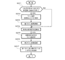
次にフローチャートを参照しつつ、車両周辺画像提供装置100の動作を説明する。図4は、車両周辺画像提供装置100による俯瞰合成画像の描画動作を示すフローチャートである。
Next, the operation of the vehicle periphery
カメラ152乃至158は、それぞれ車両200の周辺を撮影して画像データを生成する(S101)。更に、カメラ152乃至158は、それぞれ生成した画像データに、自身の識別情報(以下、「カメラ識別情報」と称する)を付加した上で制御部102内の画像描画部110における画像データ取得部112へ出力する。画像データ取得部112は、これらカメラ152乃至158によって生成された4つの画像データ、換言すれば、車両200の前方、右方、後方、左方のそれぞれに対応する画像データを取得し、視点変換部114へ出力する。
The
視点変換部114は、入力した4つの画像データ毎に、当該画像データに基づいて、公知の手法による視点変換を行い、車両200の上方を視点とする俯瞰画像の画像データを生成することによって、車両200の上方を視点とする俯瞰画像を、隣接する2つの俯瞰画像に対応する実空間の端部が重複するように描画する(S102)。視点変換部114は、生成した4つの俯瞰画像の画像データ、換言すれば、車両200の前方、右方、後方、左方のそれぞれに対応する俯瞰画像の画像データについて、当該俯瞰画像の画像データの元となった画像データに付加されていたカメラ識別情報を付加した上で画像合成部116へ出力する。
The
画像合成部116は、4つの俯瞰画像の画像データを入力すると、当該画像データに付加されているカメラ識別情報に基づいて、当該画像データが車両200の前方、右方、後方、左方のいずれに対応する俯瞰画像のものであるかを特定する。更に、画像合成部116は、マッピングメモリ104に記憶されたマッピングテーブルを参照することによって、車両200の前方、右方、後方、左方に対応する俯瞰画像の画像データ毎に、当該画像データを構成する画素毎の画像データが記憶されるべきフレームメモリ106内の記憶領域を特定する。そして、画像合成部116は、特定した記憶領域に、画素毎の画像データを記憶させる。これにより、車両200の前方、右方、後方、左方に対応する俯瞰画像が合成されて、1つの俯瞰合成画像が描画されることになる(S104)。
When the
図5は、俯瞰合成画像の一例を示す図である。図5に示す俯瞰合成画像は、車両200の前方に対応する俯瞰画像212、右方に対応する俯瞰画像214、後方に対応する俯瞰画像216、及び、左方に対応する俯瞰画像218を合成して得られる。この俯瞰合成画像において、前方に対応する俯瞰画像212と右方に対応する俯瞰画像214との重複部分222では、フレームメモリ106における所定の記憶領域に、前方に対応する俯瞰画像212の端部に対応する画像データ222bと右方に対応する俯瞰画像214の端部に対応する画像データ222aとが記憶された後、右方に対応する俯瞰画像214の端部に対応する画像データ222aが後述するライン画像で上書きされることで、前方に対応する俯瞰画像212が優先して表出している。これは、以下の理由による。すなわち、図6(a)に示す車両200の前方を撮影するカメラ152の画角θ1と、図6(b)に示す車両200の右方を撮影するカメラ154の画角θ2とを比較すると、カメラ152の画角θ1の方が撮影範囲が狭いために小さい。このため、カメラ152によって生成された画像データに対応する俯瞰画像は、カメラ154によって生成された画像データに対応する俯瞰画像よりも歪みが小さい。従って、カメラ152によって生成された画像データに対応する俯瞰画像、すなわち、前方に対応する俯瞰画像212を優先して表出させることが望ましいことによる。
FIG. 5 is a diagram illustrating an example of the overhead view composite image. 5 combines an
再び、図5に戻って説明する。上述と同様に、車両200の前方を撮影するカメラ152の画角が車両200の左方を撮影するカメラ158の画角より小さいことに鑑み、前方に対応する俯瞰画像212と左方に対応する俯瞰画像218との重複部分228では、フレームメモリ106における所定の記憶領域に、前方に対応する俯瞰画像212の端部に対応する画像データ228bと左方に対応する俯瞰画像218の端部に対応する画像データ228aとが記憶された後、左方に対応する俯瞰画像218の端部に対応する画像データ228aが後述するライン画像で上書きされることで、前方に対応する俯瞰画像212が優先して表出している。更には、車両200の後方を撮影するカメラ156の画角が車両200の右方を撮影するカメラ154の画角より小さいことに鑑み、後方に対応する俯瞰画像212と右方に対応する俯瞰画像214との重複部分224では、フレームメモリ106における所定の記憶領域に、後方に対応する俯瞰画像216の端部に対応する画像データ224bと右方に対応する俯瞰画像214の端部に対応する画像データ224aとが記憶された後、右方に対応する俯瞰画像214の端部に対応する画像データ224aが後述するライン画像で上書きされることで、後方に対応する俯瞰画像216が優先して表出している。また、車両200の後方を撮影するカメラ156の画角が車両200の左方を撮影するカメラ158の画角より小さいことに鑑み、後方に対応する俯瞰画像216と左方に対応する俯瞰画像218との重複部分226では、フレームメモリ106における所定の記憶領域に、後方に対応する俯瞰画像216の端部に対応する画像データ226bと左方に対応する俯瞰画像218の端部に対応する画像データ226aとが記憶された後、左方に対応する俯瞰画像218の端部に対応する画像データ226aが後述するライン画像で上書きされることで、後方に対応する俯瞰画像216が優先して表出している。
Returning again to FIG. Similarly to the above, in view of the fact that the angle of view of the
再び図4に戻って説明する。俯瞰合成画像が描画されると、更に、画像合成部116は、車両200についての上方を視点とする画像に対応する画像データを、フレームメモリ106における、俯瞰合成画像によって囲まれた部分に対応する記憶領域に記憶させる。これにより、図7に示すように、車両200の前方に対応する俯瞰画像212、右方に対応する俯瞰画像214、後方に対応する俯瞰画像216、及び、左方に対応する俯瞰画像218、並びに、格俯瞰画像のつなぎ目部分に境界線画像を有してなる俯瞰合成画像によって囲まれた部分に、車両200に対応する車両画像201が描画されることになる。
Returning to FIG. 4, the description will be continued. When the overhead view composite image is drawn, the
このようにして、俯瞰合成画像と車両画像が描画された後、ライン画像が描画される。図8は、車両周辺画像提供装置100によるライン画像の描画動作を示すフローチャートである。
In this way, after the overhead view composite image and the vehicle image are drawn, the line image is drawn. FIG. 8 is a flowchart showing a line image drawing operation by the vehicle surrounding
制御部102内のライン描画部120において、物体検出部122は、隣接する2つの俯瞰画像のつなぎ目部分に対応する実空間に存在する物体を検出する。ここで、物体検出部122による4つの検出範囲と、俯瞰合成画像に4箇所存在する隣接する2つの俯瞰画像のつなぎ目部分とは1対1に対応する。物体検出部122は、後段において検出結果がどのつなぎ目部分に対応するものであるかを特定可能とすべく、検出結果に、対応する隣接する2つの俯瞰画像のつなぎ目部分の識別情報を付加した上でライン幅設定部124へ出力する。ライン幅設定部122は、入力した検出結果に基づいて、隣接する2つの俯瞰画像のつなぎ目部分に対応する実空間に物体が存在するか否かを判定する(S201)。
In the
隣接する2つの俯瞰画像のつなぎ目部分に対応する実空間に物体が存在する場合、ライン幅設定部122は、そのつなぎ目部分に対応するライン画像の幅を初期値よりも狭く設定する(S202)。ここで、ラインの幅の初期値は、例えば、隣接する2つの俯瞰画像の重複部分の幅である。また、ラインの幅を初期値よりも小さくするとは、ライン画像の幅をゼロにすることを含む。
When an object exists in the real space corresponding to the joint portion between two adjacent overhead images, the line
更に、ライン幅設定部122は、この設定したラインの幅に、当該ライン画像に対応する画像データを記憶すべきフレームメモリ106内の記憶領域の情報を付加した上で、ライン生成部126へ出力する。ここで、ライン画像に対応する画像データを記憶すべきフレームメモリ106内の記憶領域は、隣接する2つの俯瞰画像のつなぎ目部分と1対1に対応する。従って、ライン幅設定部122は、検出結果に付加された隣接する2つの俯瞰画像のつなぎ目部分の識別情報に基づいて、ラインの画像に対応する画像データを記憶すべきフレームメモリ106内の記憶領域を特定可能である。
Further, the line
ライン生成部126は、入力したライン画像の幅に基づいて、第1のライン画像に対応する画像データを生成することにより、当該第1のライン画像を描画する(S203)。生成された第1のライン画像に対応する画像データは、当該第1のライン画像に対応する画像データを記憶すべきフレームメモリ106内の記憶領域の情報とともに、ライン選択部134へ出力される。
The
S203における第1のライン画像の描画後、あるいは、S201において隣接する2つの俯瞰画像のつなぎ目部分に対応する実空間に物体が存在しないと判定された後、次に、姿勢変化検出部128は、車両200の初期状態からの変化を示す姿勢変化量を検出する(S204)。検出された姿勢変化量は、画像消失量算出部130へ出力される。
After drawing the first line image in S203, or after determining in S201 that there is no object in the real space corresponding to the joint portion between two adjacent overhead images, the posture
画像消失量算出部130は、入力した姿勢変化量に基づいて、2つの俯瞰画像の隣接する俯瞰画像に対応する実空間の重複部分の幅を画像消失量として算出する。例えば、車両200が前方に傾斜した場合、車両200の後方を撮影するカメラ156の撮影範囲と、車両200の右方を撮影するカメラ154及び車両200の左方を撮影する158の撮影範囲との重複部分は減少する。このことは、車両200の後方に対応する俯瞰画像の実空間と車両200の右方に対応する俯瞰画像の実空間との重複部分の幅、及び、車両200の後方に対応する俯瞰画像の実空間と車両200の左方に対応する俯瞰画像の実空間との重複部分の幅が、車両200の姿勢が初期状態の場合よりも狭くなることを意味する。
Based on the input attitude change amount, the image loss
更に、画像消失量算出部130は、算出した画像消失量に基づいて、ライン画像の幅を設定する(S205)。具体的には、画像消失量算出部130は、算出した画像消失量が所定値以上の場合には、ライン画像の幅を第1の所定値に設定する。一方、画像消失量算出部130は、算出した画像消失量が所定値以下の場合には、その画像消失量にライン画像の幅を比例させて第1の所定値以下の幅とする。これにより、ライン画像の幅は常に第1の所定値以下とすることができる。
Further, the image loss
更に、画像消失量算出部130は、この設定したライン画像の幅に、当該ライン画像に対応する画像データを記憶すべきフレームメモリ106内の記憶領域の情報を付加した上で、ライン生成部126へ出力する。
Further, the image
ライン生成部126は、入力したライン画像の幅に基づいて、第2のライン画像に対応する画像データを生成することにより、当該第2のライン画像を描画する(S206)。生成された第2のライン画像に対応する画像データは、当該第2のライン画像に対応する画像データを記憶すべきフレームメモリ106内の記憶領域の情報とともに、ライン選択部134へ出力される。
The
ライン選択部134は、利用者による図示しない操作部を用いた操作指示等に応じて、S203においてライン生成部126によって生成されて入力した第1のライン画像に対応する画像データと、S206においてライン生成部132によって生成されて入力した第2のライン画像に対応する画像データとのいずれかを選択して、当該画像データを記憶すべきフレームメモリ106内の記憶領域に記憶させる(S207)。なお、S201において、隣接する2つの俯瞰画像のつなぎ目部分に対応する実空間に物体が存在しないと判定された場合には、S203における第1のライン画像の描画は行われない。この場合には、ライン選択部134は、S206においてライン生成部132によって生成されて入力した第2のライン画像に対応する画像データを、当該画像データを記憶すべきフレームメモリ106内の記憶領域に記憶させる。
The
このようにして、俯瞰合成画像、車両画像に加えてライン画像が描画されると、ディスプレイ108は、フレームメモリ106に記憶された、これら俯瞰合成画像、車両画像及びライン画像に対応する画像データを読み出して、画像を表示する。
Thus, when a line image is drawn in addition to the overhead view composite image and the vehicle image, the
上述したように、本実施形態の車両周辺画像提供装置100は、撮影によって得られた車両200の前方、右方、後方、左方のそれぞれに対応する画像データに基づいて、隣接する2つの俯瞰画像に対応する実空間の端部が重複するように、車両200の上方を視点とする俯瞰画像を描画して合成した上で、その俯瞰合成画像を構成する各俯瞰画像のつなぎ目部分に境界線の画像を付加するようにする。更に、車両周辺画像提供装置100は、俯瞰画像のつなぎ目部分に対応する実空間に物体が存在する場合には、つなぎ目部分に対応するラインの画像の幅を変更することによって、その物体に対応する画像を表出させることを可能とし、車両の姿勢が変化することによって、俯瞰画像に対応する撮影範囲が変化した場合には、その車両の姿勢変化量に応じてラインの画像の幅を変更することによって、そのつなぎ目部分に対応する実空間に物体が存在する場合には、当該物体に対応する画像を表出させることを可能とする。
As described above, the vehicle periphery
これにより、車両200の姿勢が変化することに伴って、当該車両100に取り付けられたカメラ152乃至158の撮影範囲が変化した場合であっても、図9に示すように、隣接する2つの俯瞰画像に対応する実空間232及び234の端部が離れて死角が生じることが防止され、運転者は、俯瞰画像のつなぎ目部分に対応する実空間に物体202が存在すること、及び、その物体202の形状を認識することが可能となる。また、図10に示すように、俯瞰画像216と俯瞰画像218のつなぎ目部分に対応する実空間に物体が存在する場合は、俯瞰画像212と俯瞰画像214のつなぎ目部分に対応するライン画像242、俯瞰画像214と俯瞰画像216のつなぎ目部分に対応するライン画像244、俯瞰画像216と俯瞰画像218のつなぎ目部分に対応するライン画像246、俯瞰画像218と俯瞰画像212のつなぎ目部分に対応するライン画像248のうち、俯瞰画像216と俯瞰画像218のつなぎ目部分に対応するライン画像246の幅を小さくする、あるいは、車両200の姿勢変化量に応じてライン画像246の幅を変更することで、その物体に対応する画像203を表出させることが可能となり、運転者は、どのような形状の物体がどの位置に存在するのかを認識することが可能となる。
As a result, even when the shooting range of the
なお、上述した実施形態では、図8に示すように、第1のライン画像を描画するとともに第2のライン画像を描画して、これらのいずれかを選択するようにしたが、S201乃至S203の動作のみにより第1のライン画像のみを描画してもよく、S204乃至206の動作によって第2のライン画像のみを描画してもよい。 In the above-described embodiment, as shown in FIG. 8, the first line image is drawn and the second line image is drawn and any one of them is selected. Only the first line image may be drawn by only the operation, or only the second line image may be drawn by the operations of S204 to 206.
以上、説明したように、本発明に係る画像処理装置は、車両周辺の監視の確実性を向上させることが可能であり、画像処理装置及び画像処理方法として有用である。 As described above, the image processing apparatus according to the present invention can improve the certainty of monitoring around the vehicle, and is useful as an image processing apparatus and an image processing method.
100 車両周辺画像提供装置
102 制御部
104 マッピングメモリ
106 フレームメモリ
108 ディスプレイ
110 画像描画部
120 ライン描画部
112 画像データ取得部
114 視点変換部
116 画像合成部
122 物体検出部
124 ライン幅設定部
126 ライン生成部
128 姿勢変化検出部
130 画像消失量算出部
132 ライン生成部
134 ライン選択部
152、154、156、158 カメラ
162、164、166、168 超音波センサ
DESCRIPTION OF
Claims (11)
前記車両に取り付けられ、該車両の周辺を撮影して画像データを生成する複数の撮影手段と、
前記撮影手段のそれぞれによって生成された前記画像データ毎に、該画像データに基づいて、前記車両の上方を視点とする俯瞰画像を、隣接する2つの俯瞰画像に対応する実空間の端部が重複するように描画する俯瞰画像描画手段と、
前記画像描画手段により描画された前記画像データ毎の俯瞰画像を所定の配置で合成して俯瞰合成画像を描画する画像合成手段と、
前記画像合成手段により描画された前記俯瞰合成画像に含まれる俯瞰画像のつなぎ目部分に対応する実空間に存在する物体を検出する物体検出手段と、
前記俯瞰合成画像に含まれる俯瞰画像のつなぎ目部分である重複部分のうち、一方の重複部分を境界線画像が重畳される重複部分として設定するとともに、前記物体検出手段により重複部分に対応する実空間に存在する物体が検出された場合に、前記境界線画像の幅を変更する境界線幅設定手段と、
前記画像合成手段により描画された前記俯瞰合成画像に含まれる俯瞰画像のつなぎ目部分において、前記境界線幅設定手段により設定された幅の境界線画像を前記境界線画像が重畳される重複部分として設定された前記一方の俯瞰画像の重複部分に重畳させて、境界線付き俯瞰合成画像を描画する画像付加手段とを有することを特徴とする画像処理装置。 An image processing apparatus that processes an image obtained by photographing the periphery of a vehicle,
A plurality of photographing means attached to the vehicle and photographing the periphery of the vehicle to generate image data;
For each of the image data generated by each of the photographing means, based on the image data, an overhead image having a viewpoint above the vehicle is overlapped, and ends of the real space corresponding to two adjacent overhead images are overlapped A bird's-eye view image drawing means for drawing,
Image compositing means for compositing the bird's-eye view image for each of the image data drawn by the image drawing means in a predetermined arrangement and drawing the bird's-eye view composite image;
Object detection means for detecting an object existing in a real space corresponding to a joint portion of the overhead view image included in the overhead view composite image drawn by the image composition means;
Among the overlapping portions that are the joint portions of the overhead view image included in the overhead view composite image, one of the overlapping portions is set as an overlapping portion on which the boundary line image is superimposed, and the real space corresponding to the overlapping portion by the object detection unit Boundary width setting means for changing the width of the boundary line image when an object existing in is detected,
The overlap portion Oite the joint portion of the overhead image included in the overhead synthesized image drawn by the image synthesizing means, the boundary image of the set width by the border width setting means the boundary line image is superimposed And an image adding means for drawing an overhead composite image with a boundary line so as to be superimposed on an overlapping portion of the one overhead image set as described above .
前記車両に取り付けられ、該車両の周辺を撮影して画像データを生成する複数の撮影手段と、
前記撮影手段のそれぞれによって生成された前記画像データ毎に、該画像データに基づいて、前記車両の上方を視点とする俯瞰画像を、隣接する2つの俯瞰画像に対応する実空間の端部が重複するように描画する俯瞰画像描画手段と、
前記画像描画手段により描画された前記画像データ毎の俯瞰画像を所定の配置で合成して俯瞰合成画像を生成する画像合成手段と、
前記車両の姿勢変化量を検出する姿勢変化検出手段と、
前記俯瞰合成画像に含まれる俯瞰画像のつなぎ目部分である重複部分のうち、一方の重複部分を境界線画像が重畳される重複部分として設定するとともに、前記姿勢変化検出手段により検出された前記車両の姿勢変化量に基づいて、前記境界線画像の幅を変更する境界線幅設定手段と、
前記画像合成手段により描画された前記俯瞰合成画像に含まれる俯瞰画像のつなぎ目部分において、前記境界線幅設定手段により設定された幅の境界線画像を前記境界線画像が重畳される重複部分として設定された前記一方の俯瞰画像の重複部分に重畳させて、境界線付き俯瞰合成画像を描画する画像付加手段とを有することを特徴とする画像処理装置。 An image processing apparatus that processes an image obtained by photographing the periphery of a vehicle,
A plurality of photographing means attached to the vehicle and photographing the periphery of the vehicle to generate image data;
For each of the image data generated by each of the photographing means, based on the image data, an overhead image having a viewpoint above the vehicle is overlapped, and ends of the real space corresponding to two adjacent overhead images are overlapped A bird's-eye view image drawing means for drawing,
Image combining means for combining the overhead images for each of the image data drawn by the image drawing means in a predetermined arrangement to generate an overhead view synthesized image;
Attitude change detection means for detecting the attitude change amount of the vehicle;
Among the overlapping portions that are the joint portions of the overhead view images included in the overhead view composite image, one overlapping portion is set as an overlapping portion on which the boundary line image is superimposed, and the vehicle detected by the posture change detection means Border line width setting means for changing the width of the border line image based on a posture change amount;
The overlap portion Oite the joint portion of the overhead image included in the overhead synthesized image drawn by the image synthesizing means, the boundary image of the set width by the border width setting means the boundary line image is superimposed And an image adding means for drawing an overhead composite image with a boundary line so as to be superimposed on an overlapping portion of the one overhead image set as described above .
前記画像合成手段は、前記画像描画手段により描画された前記俯瞰画像に対応する画像データを、前記俯瞰画像毎に定まる前記フレームメモリ内の所定の記憶領域に記憶させ、
前記画像付加手段は、前記境界線画像に対応する画像データを、前記境界線画像毎に定まる前記フレームメモリ内の所定の記憶領域に記憶させることを特徴とする請求項1乃至5のいずれかに記載の画像処理装置。 A frame memory for storing image data corresponding to an image to be displayed;
The image synthesis means stores image data corresponding to the overhead image drawn by the image drawing means in a predetermined storage area in the frame memory determined for each overhead image,
6. The image adding unit according to claim 1, wherein image data corresponding to the boundary line image is stored in a predetermined storage area in the frame memory determined for each boundary line image. The image processing apparatus described.
前記画像合成手段は、前記マッピングテーブルに基づいて、前記画像描画手段により描画された前記俯瞰画像に対応する画素毎の画像データを、前記フレームメモリの所定の記憶領域に記憶させることを特徴とする請求項6に記載の画像処理装置。 A mapping memory for storing a mapping table for storing a mapping table indicating a correspondence relationship between a pixel position of the overhead image drawn by the image drawing means and a storage area in the frame memory;
The image synthesizing unit stores image data for each pixel corresponding to the overhead image drawn by the image drawing unit in a predetermined storage area of the frame memory based on the mapping table. The image processing apparatus according to claim 6.
前記車両の前方を撮影する第1の撮影手段と、
前記車両の右方を撮影する第2の撮影手段と、
前記車両の後方を撮影する第3の撮影手段と、
前記車両の左方を撮影する第4の撮影手段とを有することを特徴とする請求項1乃至8のいずれかに記載の画像処理装置。 The plurality of photographing means includes
First photographing means for photographing the front of the vehicle;
A second photographing means for photographing the right side of the vehicle;
Third imaging means for imaging the rear of the vehicle;
The image processing apparatus according to claim 1, further comprising a fourth photographing unit that photographs the left side of the vehicle.
前記車両に取り付けられた複数の撮影手段により前記車両の周辺を撮影して画像データを生成する撮影ステップと、
前記撮影ステップによって前記撮影手段のそれぞれによって生成された前記画像データ毎に、該画像データに基づいて、前記車両の上方を視点とする俯瞰画像を、隣接する2つの俯瞰画像に対応する実空間の端部が重複するように描画する俯瞰画像描画ステップと、
前記画像描画ステップにより描画された前記画像データ毎の俯瞰画像を所定の配置で合成して俯瞰合成画像を描画する画像合成ステップと、
前記前記画像合成ステップにより描画された前記俯瞰合成画像に含まれる俯瞰画像のつなぎ目部分に対応する実空間に存在する物体を検出する物体検出ステップと、
前記俯瞰合成画像に含まれる俯瞰画像のつなぎ目部分である重複部分のうち、一方の俯瞰画像の重複部分を境界線画像が重畳される重複部分として設定するとともに、前記物体検出ステップにより重複部分に対応する実空間に存在する物体が検出された場合に、前記境界線画像の幅を変更する境界線幅設定ステップと、
前記画像合成ステップにより描画された前記俯瞰合成画像に含まれる俯瞰画像のつなぎ目部分において、前記境界線幅設定ステップにより設定された幅の境界線画像を前記境界線画像が重畳される重複部分として設定された前記一方の俯瞰画像の重複部分に重畳させて、境界線付き俯瞰合成画像を描画する画像付加ステップとを有することを特徴とする画像処理方法。 An image processing method for processing an image obtained by photographing the periphery of a vehicle,
A photographing step of photographing the periphery of the vehicle by a plurality of photographing means attached to the vehicle to generate image data;
For each of the image data generated by each of the photographing means in the photographing step, based on the image data, an overhead view image with the viewpoint above the vehicle as a viewpoint is displayed in the real space corresponding to two adjacent overhead view images. A bird's-eye view image drawing step for drawing so that the ends overlap,
An image compositing step for compositing the bird's-eye view image for each of the image data rendered by the image rendering step in a predetermined arrangement to render an overhead view composite image;
An object detection step of detecting an object existing in a real space corresponding to a joint portion of the overhead view image included in the overhead view composite image drawn by the image synthesis step;
Among overlapping parts that are joint parts of the overhead image included in the overhead image composite image, the overlapping part of one overhead image is set as an overlapping part on which the boundary line image is superimposed , and the object detection step supports the overlapping part A boundary line width setting step for changing the width of the boundary line image when an object existing in the real space is detected;
The overlap portion Oite the joint portion of the overhead image included in the overhead synthesized image drawn by the image synthesizing step, a border image of the set width by the border width setting step the boundary line image is superimposed And an image addition step of drawing an overhead composite image with a boundary line so as to be superimposed on an overlapping portion of the one overhead image set as described above .
前記車両に取り付けられた複数の撮影手段により前記車両の周辺を撮影して画像データを生成する撮影ステップと、
前記撮影ステップによって前記撮影手段のそれぞれによって生成された前記画像データ毎に、該画像データに基づいて、前記車両の上方を視点とする俯瞰画像を、隣接する2つの俯瞰画像に対応する実空間の端部が重複するように描画する俯瞰画像描画ステップと、
前記画像描画ステップにより描画された前記画像データ毎の俯瞰画像を所定の配置で合成して俯瞰合成画像を生成する画像合成ステップと、
前記車両の姿勢変化量を検出する姿勢変化検出ステップと、
前記俯瞰合成画像に含まれる俯瞰画像のつなぎ目部分である重複部分のうち、一方の重複部分を境界線画像が重畳される重複部分として設定するとともに、前記姿勢変化検出ステップにより検出された前記車両の姿勢変化量に基づいて、前記境界線画像の幅を変更する境界線幅設定ステップと、
前記画像合成ステップにより描画された前記俯瞰合成画像に含まれる俯瞰画像のつなぎ目部分において、前記境界線幅設定ステップにより設定された幅の境界線画像を前記境界線画像が重畳される重複部分として設定された前記一方の俯瞰画像の重複部分に重畳させて、境界線付き俯瞰合成画像を描画する画像付加ステップとを有することを特徴とする画像処理方法。 An image processing method for processing an image obtained by photographing the periphery of a vehicle,
A photographing step of photographing the periphery of the vehicle by a plurality of photographing means attached to the vehicle to generate image data;
For each of the image data generated by each of the photographing means in the photographing step, based on the image data, an overhead view image with the viewpoint above the vehicle as a viewpoint is displayed in the real space corresponding to two adjacent overhead view images. A bird's-eye view image drawing step for drawing so that the ends overlap,
An image synthesis step of generating an overhead view synthesized image by synthesizing the overhead view image for each of the image data drawn by the image drawing step in a predetermined arrangement;
An attitude change detecting step for detecting an attitude change amount of the vehicle;
Among the overlapping portions that are the joint portions of the overhead view image included in the overhead view composite image, one overlapping portion is set as an overlapping portion on which the boundary line image is superimposed, and the vehicle detected by the posture change detection step A boundary line width setting step for changing the width of the boundary line image based on the posture change amount;
The overlap portion Oite the joint portion of the overhead image included in the overhead synthesized image drawn by the image synthesizing step, a border image of the set width by the border width setting step the boundary line image is superimposed And an image addition step of drawing an overhead composite image with a boundary line so as to be superimposed on an overlapping portion of the one overhead image set as described above .
Priority Applications (3)
| Application Number | Priority Date | Filing Date | Title |
|---|---|---|---|
| JP2007267886A JP5120880B2 (en) | 2007-10-15 | 2007-10-15 | Image processing apparatus and image processing method |
| US12/244,344 US8155385B2 (en) | 2007-10-15 | 2008-10-02 | Image-processing system and image-processing method |
| US13/409,538 US9098928B2 (en) | 2007-10-15 | 2012-03-01 | Image-processing system and image-processing method |
Applications Claiming Priority (1)
| Application Number | Priority Date | Filing Date | Title |
|---|---|---|---|
| JP2007267886A JP5120880B2 (en) | 2007-10-15 | 2007-10-15 | Image processing apparatus and image processing method |
Publications (2)
| Publication Number | Publication Date |
|---|---|
| JP2009100095A JP2009100095A (en) | 2009-05-07 |
| JP5120880B2 true JP5120880B2 (en) | 2013-01-16 |
Family
ID=40534240
Family Applications (1)
| Application Number | Title | Priority Date | Filing Date |
|---|---|---|---|
| JP2007267886A Active JP5120880B2 (en) | 2007-10-15 | 2007-10-15 | Image processing apparatus and image processing method |
Country Status (2)
| Country | Link |
|---|---|
| US (2) | US8155385B2 (en) |
| JP (1) | JP5120880B2 (en) |
Families Citing this family (48)
| Publication number | Priority date | Publication date | Assignee | Title |
|---|---|---|---|---|
| WO2007015446A1 (en) * | 2005-08-02 | 2007-02-08 | Nissan Motor Co., Ltd. | Device for monitoring around vehicle and method for monitoring around vehicle |
| US20090128630A1 (en) * | 2006-07-06 | 2009-05-21 | Nissan Motor Co., Ltd. | Vehicle image display system and image display method |
| JP5072576B2 (en) * | 2007-12-20 | 2012-11-14 | アルパイン株式会社 | Image display method and image display apparatus |
| JP5344227B2 (en) * | 2009-03-25 | 2013-11-20 | アイシン精機株式会社 | Vehicle periphery monitoring device |
| JP5035284B2 (en) * | 2009-03-25 | 2012-09-26 | 株式会社日本自動車部品総合研究所 | Vehicle periphery display device |
| JP2010258691A (en) * | 2009-04-23 | 2010-11-11 | Sanyo Electric Co Ltd | Maneuver assisting apparatus |
| JP5444338B2 (en) * | 2009-05-25 | 2014-03-19 | パナソニック株式会社 | Vehicle perimeter monitoring device |
| DE102009024062A1 (en) * | 2009-06-05 | 2010-12-09 | Valeo Schalter Und Sensoren Gmbh | Apparatus and method for displaying objects in a vehicle environment |
| TW201103787A (en) * | 2009-07-31 | 2011-02-01 | Automotive Res & Testing Ct | Obstacle determination system and method utilizing bird's-eye images |
| JP5500369B2 (en) * | 2009-08-03 | 2014-05-21 | アイシン精機株式会社 | Vehicle peripheral image generation device |
| TWI417639B (en) * | 2009-12-30 | 2013-12-01 | Ind Tech Res Inst | Method and system for forming surrounding seamless bird-view image |
| TWI392366B (en) * | 2009-12-31 | 2013-04-01 | Ind Tech Res Inst | Method and system for generating surrounding seamless bird-view image with distance interface |
| JP5462008B2 (en) * | 2010-01-25 | 2014-04-02 | 株式会社タダノ | Image display system |
| JP5709675B2 (en) * | 2011-07-07 | 2015-04-30 | クラリオン株式会社 | Vehicle surrounding imaging system |
| JP5483120B2 (en) * | 2011-07-26 | 2014-05-07 | アイシン精機株式会社 | Vehicle perimeter monitoring system |
| WO2013032371A1 (en) * | 2011-08-30 | 2013-03-07 | Volvo Technology Corporation | Vehicle security system and method for using the same |
| US10063815B1 (en) * | 2011-09-26 | 2018-08-28 | Jenesia1, Inc. | Mobile communication platform |
| JP5682788B2 (en) * | 2011-09-27 | 2015-03-11 | アイシン精機株式会社 | Vehicle periphery monitoring device |
| JP5754605B2 (en) * | 2011-11-01 | 2015-07-29 | アイシン精機株式会社 | Obstacle alarm device |
| JP5704416B2 (en) * | 2011-11-01 | 2015-04-22 | アイシン精機株式会社 | Obstacle alarm device |
| JP5796638B2 (en) * | 2011-12-22 | 2015-10-21 | 日産自動車株式会社 | Monitoring system |
| WO2013129000A1 (en) * | 2012-02-27 | 2013-09-06 | 日産自動車株式会社 | Monitoring system |
| JP6035842B2 (en) * | 2012-04-25 | 2016-11-30 | ソニー株式会社 | Imaging apparatus, imaging processing method, image processing apparatus, and imaging processing system |
| KR101910509B1 (en) * | 2012-07-17 | 2018-10-22 | 삼성전자주식회사 | Method and apparatus for preventing screen off during automatic response system service in electronic device |
| TWI578271B (en) * | 2012-10-23 | 2017-04-11 | 義晶科技股份有限公司 | Dynamic image processing method and dynamic image processing system |
| JPWO2015129280A1 (en) * | 2014-02-26 | 2017-03-30 | 京セラ株式会社 | Image processing apparatus and image processing method |
| US20150286878A1 (en) | 2014-04-08 | 2015-10-08 | Bendix Commercial Vehicle Systems Llc | Generating an Image of the Surroundings of an Articulated Vehicle |
| US9811744B2 (en) * | 2014-07-23 | 2017-11-07 | GM Global Technology Operations LLC | Fast and robust stop line detector |
| KR101596751B1 (en) * | 2014-09-26 | 2016-02-23 | 현대자동차주식회사 | Method and apparatus for displaying blind spot customized by driver |
| US9880253B2 (en) | 2014-10-28 | 2018-01-30 | Nissan North America, Inc. | Vehicle object monitoring system |
| US9725040B2 (en) | 2014-10-28 | 2017-08-08 | Nissan North America, Inc. | Vehicle object detection system |
| US9834141B2 (en) | 2014-10-28 | 2017-12-05 | Nissan North America, Inc. | Vehicle object detection system |
| KR102300652B1 (en) * | 2015-01-19 | 2021-09-10 | 현대모비스 주식회사 | vehicle and control method thereof |
| WO2016087900A1 (en) | 2014-12-05 | 2016-06-09 | Audi Ag | Driver assistance system for a vehicle as well as method for assisting a driver of a vehicle |
| US20160193998A1 (en) * | 2015-01-02 | 2016-07-07 | Atieva, Inc. | Automatically Activated Vehicle Obstacle Viewing System |
| DE102015002923B4 (en) * | 2015-03-06 | 2023-01-12 | Mekra Lang Gmbh & Co. Kg | Display device for a vehicle, in particular a commercial vehicle |
| EP3086279A1 (en) | 2015-04-24 | 2016-10-26 | KNORR-BREMSE Systeme für Nutzfahrzeuge GmbH | Image synthesizer for a driver assisting system |
| JP6477444B2 (en) * | 2015-11-25 | 2019-03-06 | 株式会社デンソー | Display control apparatus and display control program |
| CN105761209B (en) * | 2016-03-16 | 2018-11-13 | 武汉大学 | Nuclear containment surface image joining method and system |
| JP6626817B2 (en) * | 2016-11-30 | 2019-12-25 | 京セラ株式会社 | Camera monitor system, image processing device, vehicle, and image processing method |
| CN106791325B (en) * | 2017-01-06 | 2022-08-23 | 上海寅家电子科技股份有限公司 | Automatic identification system and automatic identification method for color difference light measuring area of panoramic all-round looking system |
| JP7005269B2 (en) * | 2017-10-18 | 2022-01-21 | キヤノン株式会社 | Information processing equipment, systems, information processing methods and programs |
| JP2019080238A (en) * | 2017-10-26 | 2019-05-23 | シャープ株式会社 | Vehicle driving support device and vehicle driving support program |
| JP2021144257A (en) * | 2018-06-06 | 2021-09-24 | ソニーグループ株式会社 | Information processing device, information processing method, program, and moving object |
| JP2020074186A (en) * | 2020-01-22 | 2020-05-14 | シャープ株式会社 | Image processing device, image processing system, image processing method, and image processing program |
| KR102473404B1 (en) * | 2020-02-25 | 2022-12-02 | 삼성전기주식회사 | Apparatus for providing top view |
| WO2022074848A1 (en) * | 2020-10-09 | 2022-04-14 | 株式会社ソシオネクスト | Image processing device, image processing method, and image processing program |
| JP7366982B2 (en) * | 2021-11-24 | 2023-10-23 | 本田技研工業株式会社 | Control device, control method, and control program |
Family Cites Families (18)
| Publication number | Priority date | Publication date | Assignee | Title |
|---|---|---|---|---|
| JPH10164494A (en) * | 1996-12-03 | 1998-06-19 | Matsushita Electric Ind Co Ltd | Video processing apparatus and video processing system using the same |
| EP1179958B1 (en) * | 1999-04-16 | 2012-08-08 | Panasonic Corporation | Image processing device and monitoring system |
| EP1158804A3 (en) * | 2000-05-24 | 2003-12-17 | Matsushita Electric Industrial Co., Ltd. | Rendering device for generating a display image |
| JP3269056B2 (en) * | 2000-07-04 | 2002-03-25 | 松下電器産業株式会社 | Monitoring system |
| JP2002019556A (en) * | 2000-07-04 | 2002-01-23 | Matsushita Electric Ind Co Ltd | Monitoring system |
| JP3773433B2 (en) * | 2000-10-11 | 2006-05-10 | シャープ株式会社 | Ambient monitoring device for moving objects |
| JP3608527B2 (en) * | 2001-05-15 | 2005-01-12 | 株式会社豊田中央研究所 | Peripheral status display device |
| JP3819284B2 (en) | 2001-11-29 | 2006-09-06 | クラリオン株式会社 | Vehicle perimeter monitoring device |
| JP4744823B2 (en) * | 2004-08-05 | 2011-08-10 | 株式会社東芝 | Perimeter monitoring apparatus and overhead image display method |
| JP4956915B2 (en) * | 2005-05-20 | 2012-06-20 | 日産自動車株式会社 | Video display device and video display method |
| JP2006341641A (en) * | 2005-06-07 | 2006-12-21 | Nissan Motor Co Ltd | Video display device and video display method |
| JP4883977B2 (en) * | 2005-10-05 | 2012-02-22 | アルパイン株式会社 | Image display device for vehicle |
| JP4934308B2 (en) * | 2005-10-17 | 2012-05-16 | 三洋電機株式会社 | Driving support system |
| JP4681432B2 (en) * | 2005-11-28 | 2011-05-11 | アルパイン株式会社 | In-vehicle peripheral image display device |
| JP4807104B2 (en) * | 2006-03-01 | 2011-11-02 | 日産自動車株式会社 | Vehicle surrounding monitoring system and image display method |
| JP4656005B2 (en) * | 2006-06-02 | 2011-03-23 | 日産自動車株式会社 | Image processing system and image processing method |
| US7728879B2 (en) * | 2006-08-21 | 2010-06-01 | Sanyo Electric Co., Ltd. | Image processor and visual field support device |
| JP4859652B2 (en) | 2006-12-15 | 2012-01-25 | アルパイン株式会社 | Image display device |
-
2007
- 2007-10-15 JP JP2007267886A patent/JP5120880B2/en active Active
-
2008
- 2008-10-02 US US12/244,344 patent/US8155385B2/en active Active
-
2012
- 2012-03-01 US US13/409,538 patent/US9098928B2/en not_active Expired - Fee Related
Also Published As
| Publication number | Publication date |
|---|---|
| JP2009100095A (en) | 2009-05-07 |
| US20090097708A1 (en) | 2009-04-16 |
| US20120154592A1 (en) | 2012-06-21 |
| US8155385B2 (en) | 2012-04-10 |
| US9098928B2 (en) | 2015-08-04 |
Similar Documents
| Publication | Publication Date | Title |
|---|---|---|
| JP5120880B2 (en) | Image processing apparatus and image processing method | |
| JP6099333B2 (en) | Image generation apparatus, image display system, parameter acquisition apparatus, image generation method, and parameter acquisition method | |
| JP5383576B2 (en) | Imaging apparatus, imaging method, and program | |
| JP5835383B2 (en) | Information processing method, information processing apparatus, and program | |
| JP5143009B2 (en) | Video display device and video display method | |
| US20190199940A1 (en) | Image display apparatus | |
| JP5835384B2 (en) | Information processing method, information processing apparatus, and program | |
| JP2009524171A (en) | How to combine multiple images into a bird's eye view image | |
| JP2009017020A (en) | Image processing apparatus and display image generation method | |
| JP2005050035A (en) | Image photographing apparatus and image processing method | |
| JP2013110712A5 (en) | ||
| JP2007295547A (en) | Digital camera | |
| JP5178454B2 (en) | Vehicle perimeter monitoring apparatus and vehicle perimeter monitoring method | |
| KR101964864B1 (en) | Distortion Correction Method of Around View Image of Vehicle | |
| JP6740991B2 (en) | Display processor | |
| JP2020028027A (en) | Periphery display device for vehicle | |
| JP2016168877A (en) | Vehicle visual recognition device | |
| JP6890288B2 (en) | Image processing equipment, image display system and image processing method | |
| JP2007041791A (en) | Overhead image display system and overhead image display method | |
| JP2015171106A (en) | Vehicle peripheral image display device and vehicle peripheral image display method | |
| JP4846627B2 (en) | Display control device | |
| JP4266736B2 (en) | Image processing method and apparatus | |
| KR20100019605A (en) | Rear camera display system | |
| JP2010130413A (en) | Peripheral state display device | |
| JP4262013B2 (en) | Image processing method and image generation apparatus |
Legal Events
| Date | Code | Title | Description |
|---|---|---|---|
| A621 | Written request for application examination |
Free format text: JAPANESE INTERMEDIATE CODE: A621 Effective date: 20100927 |
|
| A521 | Request for written amendment filed |
Free format text: JAPANESE INTERMEDIATE CODE: A523 Effective date: 20111116 |
|
| A977 | Report on retrieval |
Free format text: JAPANESE INTERMEDIATE CODE: A971007 Effective date: 20120724 |
|
| A131 | Notification of reasons for refusal |
Free format text: JAPANESE INTERMEDIATE CODE: A131 Effective date: 20120801 |
|
| A521 | Request for written amendment filed |
Free format text: JAPANESE INTERMEDIATE CODE: A523 Effective date: 20120927 |
|
| TRDD | Decision of grant or rejection written | ||
| A01 | Written decision to grant a patent or to grant a registration (utility model) |
Free format text: JAPANESE INTERMEDIATE CODE: A01 Effective date: 20121017 |
|
| A01 | Written decision to grant a patent or to grant a registration (utility model) |
Free format text: JAPANESE INTERMEDIATE CODE: A01 |
|
| A61 | First payment of annual fees (during grant procedure) |
Free format text: JAPANESE INTERMEDIATE CODE: A61 Effective date: 20121017 |
|
| FPAY | Renewal fee payment (event date is renewal date of database) |
Free format text: PAYMENT UNTIL: 20151102 Year of fee payment: 3 |
|
| R150 | Certificate of patent or registration of utility model |
Free format text: JAPANESE INTERMEDIATE CODE: R150 Ref document number: 5120880 Country of ref document: JP Free format text: JAPANESE INTERMEDIATE CODE: R150 |