EP1179968A2 - Structure autour d'un haut-parleur - Google Patents
Structure autour d'un haut-parleur Download PDFInfo
- Publication number
- EP1179968A2 EP1179968A2 EP01306597A EP01306597A EP1179968A2 EP 1179968 A2 EP1179968 A2 EP 1179968A2 EP 01306597 A EP01306597 A EP 01306597A EP 01306597 A EP01306597 A EP 01306597A EP 1179968 A2 EP1179968 A2 EP 1179968A2
- Authority
- EP
- European Patent Office
- Prior art keywords
- speaker unit
- speaker
- sound
- board
- frame
- Prior art date
- Legal status (The legal status is an assumption and is not a legal conclusion. Google has not performed a legal analysis and makes no representation as to the accuracy of the status listed.)
- Granted
Links
Images


Classifications
-
- H—ELECTRICITY
- H04—ELECTRIC COMMUNICATION TECHNIQUE
- H04R—LOUDSPEAKERS, MICROPHONES, GRAMOPHONE PICK-UPS OR LIKE ACOUSTIC ELECTROMECHANICAL TRANSDUCERS; ELECTRIC HEARING AIDS; PUBLIC ADDRESS SYSTEMS
- H04R1/00—Details of transducers, loudspeakers or microphones
- H04R1/02—Casings; Cabinets ; Supports therefor; Mountings therein
- H04R1/025—Arrangements for fixing loudspeaker transducers, e.g. in a box, furniture
-
- H—ELECTRICITY
- H04—ELECTRIC COMMUNICATION TECHNIQUE
- H04R—LOUDSPEAKERS, MICROPHONES, GRAMOPHONE PICK-UPS OR LIKE ACOUSTIC ELECTROMECHANICAL TRANSDUCERS; ELECTRIC HEARING AIDS; PUBLIC ADDRESS SYSTEMS
- H04R5/00—Stereophonic arrangements
- H04R5/02—Spatial or constructional arrangements of loudspeakers
- H04R5/023—Spatial or constructional arrangements of loudspeakers in a chair, pillow
-
- H—ELECTRICITY
- H04—ELECTRIC COMMUNICATION TECHNIQUE
- H04R—LOUDSPEAKERS, MICROPHONES, GRAMOPHONE PICK-UPS OR LIKE ACOUSTIC ELECTROMECHANICAL TRANSDUCERS; ELECTRIC HEARING AIDS; PUBLIC ADDRESS SYSTEMS
- H04R1/00—Details of transducers, loudspeakers or microphones
- H04R1/20—Arrangements for obtaining desired frequency or directional characteristics
- H04R1/22—Arrangements for obtaining desired frequency or directional characteristics for obtaining desired frequency characteristic only
- H04R1/28—Transducer mountings or enclosures modified by provision of mechanical or acoustic impedances, e.g. resonator, damping means
- H04R1/2807—Enclosures comprising vibrating or resonating arrangements
- H04R1/283—Enclosures comprising vibrating or resonating arrangements using a passive diaphragm
- H04R1/2834—Enclosures comprising vibrating or resonating arrangements using a passive diaphragm for loudspeaker transducers
Definitions
- the present invention relates to a compact, lightweight, and simple speaker system and/or a structure around a speaker that enables to reproduce sounds, including heavy low-pitched sounds, with high fidelity.
- the present invention is also applicable to a minicomponent stereo, television, telephone, radio cassette recorder, built-in speaker for personal computer, 5.1 channel speaker, or the like.
- the present invention is applicable to a speaker used inside a pillow or inside the pillow portion of an easy chair etc.
- the present invention is applicable to a back sound screening board that is located near a speaker to improve sound effects.
- Acoustic apparatus called speakers usually transmit sound by converting electrical sound signals output from an amplifier or the like to sound vibrations by the use of electromagnetic or electrostatic stress, transmitting the sound vibrations to a vibrating board consisting of a cone paper etc., and vibrating air between the vibrating board and a listener's eardrums properly.
- Such speakers are ranging for large business concerns, including products for generating loud sounds used by musicians at open-air concerts, household stereos, minicomponents, radio cassette recorders, and headphones.
- 5.1 channel speakers were also developed and have recently been spreading as household stereos.
- Fig. 11 is a horizontal cross-sectional view of a conventional household stereo speaker.
- a fitting hole corresponding to the size of the speaker unit 21 is made in a baffle board 25, which forms a front board.
- the speaker unit 21 is fitted into the hole airtightly so that a vibrating board consisting of a cone paper 27 of the speaker unit 21 blocks the hole. This prevents air from flowing from the inside of the baffle board 25 to the outside of the baffle board 25 and vice versa.
- the speaker unit 21 is fixed firmly onto the baffle board 25 by inserting, for example, wood screws (not shown) from the front into tapped holes (not shown) in a frame of the speaker unit 21 and tightening them.
- the primary object of the baffle board 25 is to isolate a sound wave which is generated in front of the cone paper 27 from a sound wave which is generated behind the cone paper 27 and to prevent them from interfering with each other.
- sound waves with phases opposite to each other will be generated.
- Mixing sound waves with phases opposite to each other, that is to say, a sound wave 5 and a sound wave 5' will result in zero. That is to say, a sound which is generated by the speaker unit 21 will vanish before it can reach a listener's ears 29 and 30.
- the baffle board 25 must consist of a board of infinitely great size so that it can prevent air from flowing from the inside of the baffle board 25 to the outside of the baffle board 25 and vice versa. Moreover, the baffle board 25 itself should be heavy and strong and should not vibrate. Furthermore, the baffle board 25 should be fixed firmly.
- a high air-density portion (hereinafter referred to as a "positive” for convenience of explanation) appears in front of the cone paper 27 and a low air-density portion (hereinafter referred to as a "negative” for convenience of explanation) appears behind the cone paper 27.
- a low air-density portion (negative) appears in front of the cone paper 27 and a high air-density portion (positive) appears behind the cone paper 27. Isolating the positive from the negative will prevent a sound at a low compass from attenuating.
- sound waves may cancel out each other by subtraction or may increase their intensity by addition. Therefore, in order to make a speaker, which can reproduce a sound with high fidelity at a predetermined level, it is necessary to design a speaker box or an enclosure, in consideration of the frequency and phase of waves which interfere with each other.
- the speaker box 23 usually resonates only the air inside. That is to say, the enclosure member etc. of its resonance box, including the baffle board 25, do not vibrate or resonate.
- the speaker box 23 is therefore heavy and strong.
- a wadding-like sound absorbing material 31 is attached to its inner wall.
- the sound absorbing material 31 absorbs the sound wave 5'. That is to say, the sound absorbing material 31 absorbs harmful waves generated, for example, a sound reflected by the inner wall of the resonance box.
- a listener catches not only direct sounds from the cone papers 27 and 28, viz. the L-channel sound wave 5 and the R-channel sound wave 6 but also reverberations produced by an inner wall 32, a floor 33, and a ceiling 34 of a listening room. This is an ordinary listening method.
- timbre will vary with the fixtures of the listening room, the location of a listener, or his/her posture. This is a well-known fact.
- timbre will not vary with the fixtures of the listening room, his/her location, or his/her posture. This is well-known and natural. Only temperature, atmospheric pressure, and humidity around a listener's ears may have an influence on the above direct sounds and the influence on the timbre is slight in an ordinary atmosphere.
- the frames etc. (not shown) of the miniature speakers are joined firmly to members etc. (not shown) of the headphones with, for example, an adhesive so that the members etc. of the headphones do not vibrate unnecessarily.
- speaker units and fitting portions to which they are fixed are joined reliably with wood screws or an adhesive in order to avoid noise produced by the above unnecessary vibrations.
- a "passive-radiation type freely-vibrating board without a drivingvoice coil 92 etc.” “ (hereinafter referred to as a "passive radiator”) 82 and a cone paper 27 of a speaker unit 91 are located on one baffle board.
- the driving force of the voice coil 92 causes the cone paper 27 to move forward and backward.
- a positive sound wave 5 is generated in front of the cone paper 27 and a negative sound wave 5' is generated behind the cone paper 27.
- the negative sound wave 5' is converted to a positive sound wave by the interference action of a partition board 93 and presses the passive radiator 82 forward.
- a positive sound wave 50 therefore is generated.
- the most conventional type of speaker is a large-sized stationary speaker consisting of two or more heavy and strong enclosures. These enclosures are independent of one another. If there are two enclosures, one is used only for L-channel sound and the other is used only for R-channel sound. Without a device, it will be difficult for the other types of speakers to reproduce the original sound with high fidelity and to reproduce heavy low-pitched sounds with presence.
- Headphones are well-known as means for listeners to easily and reliably reproduce powerful heavy low-pitched sounds with a stereophonic effect peculiar to a stereo. However, many people dislike them because of their uncomfortableness or obstacle cords.
- an ear and a speaker unit applied to it are covered together with, for example, a rigid cover with a cushion in order to shut off the ear from sound which comes from the other channel and the outside. Therefore, even when a speaker unit and an ear are a short distance away, sound which comes from the speaker unit will be very faint.
- a configuration in which one of two speaker units outputs only L-channel sound and the other outputs only R-channel sound may be adopted.
- these two speaker units are located at both ends of one lightweight plastic enclosure (not shown).
- L-channel sound waves interfere with R-channel sound waves via the lightweight enclosure.
- the distance between the two speaker units is short, so the L-channel and R-channel sound waves will mix in the air before they reach a listener's ears. That is to say, even if a stereo is used, the listener cannot enjoy its stereophonic effect.
- an object of the present invention is to provide powerful high-fidelity heavy low-pitched sounds and a stereophonic effect, which could obtain only by high-quality headphones or a large-sized speaker, to a listener.
- the attenuation of sound should be minimized even in a listening room the sound absorbing structure of which is not desirable in terms of sound effects.
- a speaker without a resonance box will be able to meet the above conditions.
- Another object of the present invention is to provide a speaker used in a pillow, being a piece of bedding, or the pillow portion of an easy chair for listening to, for example, music.
- Still another object of the present invention is to provide a miniature, lightweight, and low-cost speaker which can reproduce clear sounds not only to conventional audio and video apparatus but also to electric and electronic apparatus for which importance has not been attached to tone quality.
- a speaker unit a direct sound transmitting section for transmitting only direct sounds which come from the front of the speaker unit, and a back sound screening section for screening out indirect sounds which come from the back of the speaker unit and travel forward are included.
- a frame of the speaker unit is attached to the baffle board so that the frame of the speaker unit can move freely in the direction in which a cone paper vibrates with strokes being much the same as the amplitude of the vibrations of the cone paper.
- a lightweight baffle board without a resonance box functions as a back sound screening board. Even if the baffle board is not fixed firmly, the same sound that is reproduced by a large-sized high-output speaker can be obtained by a small-sized low-output speaker.
- the baffle board functions especially to prevent low-pitched sounds from canceling out each other. As a result, clear, powerful, and high-fidelity reproduced sounds can be obtained without a resonance box.
- Space occupied by a speaker can be minimized, which enables a freer arrangement.
- a fitting guide with a concave portion which can house the frame with room outside the edge of the frame is formed around the hole portion made in the baffle board and the frame is located in the concave portion through a vibration absorbing member.
- a fitting guide with a concave portion which can house the frame or an outer portion joined unitarily to the frame with room outside the edge of the frame or the outer portion is included and the frame or the outer portion is located in the concave portion with a vibration absorbing member between.
- the fitting guide being another part is included.
- this fitting guide is popular among acoustic maniacs for being able to be attached to a ready-made article.
- the fitting guide and the vibration absorbing member can be sold separately from a speaker.
- an L-channel dedicated speaker unit in which speaker units for outputting L-channel sound and R-channel sound independently to produce a stereophonic effect are located so that the speaker units face a listener's left and right ears respectively, an L-channel dedicated speaker unit, a first baffle board for holding the L-channel dedicated speaker unit flexibly with a vibration absorbing member between, an R-channel dedicated speaker unit, a second baffle board for holding the R-channel dedicated speaker unit flexibly with a vibration absorbing member between, and a vibration absorbing member between the first baffle board and the second baffle board are included and the first baffle board and the second baffle board are joined flexibly.
- Low-pitched sounds are not canceled and the distinction between the L-channel and the R-channel will not vanish. Moreover, harmful indirect sounds are eliminated by a sound absorbing material and only direct sounds reach a listener's ears. Therefore, powerful high-fidelity heavy low-pitched sounds and a stereophonic effect, which could obtain only by quality headphones or a large-sized speaker system, can be provided to a listener.
- a speaker system according to this aspect of the present invention and headphones differ. That is to say, a speaker system according to this aspect of the present invention combines the advantages of a conventional speaker system with a resonance box and those of headphones.
- a speaker system uses one compact, lightweight, and simple speaker box, so it has a wide range of applications. For example, it is applicable to a simulation training apparatus or simulation game apparatus as a part of equipment for audiovisual education.
- speaker units embedded within a pillow being a piece of bedding, or the pillow portion of an easy chair and a cushion material which serves not only as a cushion material for the pillow or the pillow portion but also as the direct sound transmitting section and the back sound screening section are included.
- short tubes of hard resin with a thickness of between 0.5 and 1.5 millimeters, an outside diameter of between 5 and 15 millimeters, and a length of between 5 and 20 millimeters are included in the direct sound transmitting section and the back sound screening section.
- back sound screening boards which are located nearly on a plane extending from the edge of a vibrating board of a speaker so that space in front of the vibrating board is isolated from space behind the vibrating board and which are faced at almost right angles to a listener are included.
- the loudness of sound reproduced by a small-sized low-output speaker is equal to that of sound reproduced by a large-sized high-output speaker.
- back sound screening boards having a mechanism in which the relative positions are maintained without touching a speaker frame or by connecting with a speaker frame flexibly are included.
- folding back sound screening boards are included.
- the back sound screening boards which are made of a foamed chloroethylene board, a wooden board, or a veneer board, have a thickness of between 1 and 10 millimeters, and have a maximum expanded external size of 3 meters or less from the center of a speaker unit are included.
- a mat with a hole portion is further provided as the back sound screening section and is mainly constructed by a bag sealing therein liquid or gel, and the surface of the cone paper is ventilated through the hole portion.
- a shape and a mounting position of the mat is the same as those of the baffle board.
- it can be applicable to an object which dislikes heaviness or stiffness, and it can meet a demand on some bending.
- it is applicable to an object which directly touches to a human body, because of its excellent touch.
- a vibration absorbing member mainly constructed by a bag sealing therein liquid or gel is positioned between the baffle board and the frame.
- the frame is located in the concave portion through a vibration absorbing member mainly constructed by a bag sealing therein liquid or gel.
- the elastic vibration absorbing effect extends for a long term, in comparison with the conventional structure where the vibration absorbing member is mainly formed by a single material, such as urethane foam (sponge) or rubber, the service life of the product can be extended.
- the vibration absorbing member is mainly formed by a single material, such as urethane foam (sponge) or rubber, the service life of the product can be extended.
- constrictions are made on the bag sealing therein liquid or gel, and an irregular surface is formed by a recess-shaped or wave-shaped unevenness due to the constrictions.
- Such a constitution achieves the vibration absorbing effect as good as the structure where the vibration absorbing member is mainly formed by a foamed porous material, such as urethane foam (sponge).
- a foamed porous material such as urethane foam (sponge).
- liquid or gel In comparison with gas or sponge, liquid or gel is smaller in volume change amount when applying pressure, and therefore liquid or gel is not used as a spring if it is sealed in a piston or the like. For this reason, the vibration absorbing effect achieved by the liquid or gel sealed in the bag mainly relies on a change in the shape, and not a volume change. It is essential to keep a space for escaping the liquid or gel upon changing by a load. In the above constitution, the recess-shaped or wave-shaped uneven surface provides the escaping space for the deformed and projecting part.
- the recess-shaped or wave-shaped unevenness ensures air permeability and prevents the front and back of the cone paper from being separately sealed. Therefore, the advantages of the non-separate seal can be sufficiently achieved and thus high fidelity sound can be supplied.
- the bag mainly consists of silicone rubber.
- the gel has a stiffness and elasticity barely retaining its shape at room temperatures
- the bag is mainly formed by silicone rubber in the thickness of between 0.05 to 1 millimeter.
- the gel is mainly formed by a high water absorbability polymer consisting acrylamide cross-linking structure.
- the structure around a speaker unit according to any of the above aspects is applied to an electric or electronic apparatus for producing sound.
- electric and electronic apparatus for which importance has not been attached to tone quality can also use a miniature, lightweight, and low-cost speaker which can reproduce clear sounds.
- Fig. 1 is a cross-sectional view of a speaker showing a "basic" embodiment of the present invention.
- a frame 15 of the speaker unit 1 is attached flexibly to the baffle board 11 so that the frame 15 can move in the direction in which a cone paper 27 vibrates, that is to say, forward and backward freely with strokes being much the same as the amplitude of the vibrations of the cone paper 27.
- vibrations generated in the speaker unit 1 are absorbed so that they are not transmitted to the baffle board 11.
- a prop 3 most of the surface of which is smoothed, for example, by coating with a collar 2 pierces through the baffle board 11 at the edge portion of the hole made in it.
- a male screw is cut into the edge portion of the prop 3 and a position regulating member 50 is bolted down at a predetermined position.
- a sleeve 4 is attached to a screw hole made in the frame 15. The prop 3 fits into the sleeve 4 with the collar 2 between and the forward and backward motion of the sleeve 4, that is to say, the forward and backward motion of the frame 15 is regulated flexibly by the elastic force of vibration absorbing members 17 and 18 of urethane foam (sponge).
- the area of the baffle board 11 is finite and some of the sound wave 5' will travel to the front of the baffle board 11 around its edge. For example, however, its route to a listener's ears (not shown) is not straight. The sound wave 5' therefore will significantly attenuate before it can reach the ears. That is to say, the sound wave 5' almost never interferes with the sound wave 5. As a result, low-pitched sounds included in the sound wave 5 almost never attenuate.
- Methods 1), 2), and 3) do not have various uses and are unreal.
- Method 4) is not suitable for a compact, lightweight, and low-cost speaker system.
- the frame 15 therefore should be vibrated freely. While the weight of the frame 15 including a magnet has recently reduced with the progress of magnet materials, the weight of the frame 15 including the magnet is far greater than the total weight of a voice coil (not shown) and the cone paper 27. Moreover, usually the area of the frame 15 which vibrates air is smaller than that of the cone paper 27. Therefore, the sound wave 5' generated by the frame 15 itself is negligible.
- the baffle board 11 resonates to some extent by the sound wave 5 and radiates the sound wave 5 of increased intensity in the forward direction. That is to say, the baffle board 11 functions as what is called an "acoustic resonance reflecting board.”
- Fig. 2 is a cross-sectional view of a speaker showing an "embedded-type" embodiment of the present invention.
- a frame 15 of a speaker unit 1 is located flexibly on a baffle board 11 with vibration absorbing members 17 and 18. This is the same with the embodiment shown in Fig. 1.
- the back of the speaker unit 1 is covered with a member 40 of fibers having great elasticity, great air-permeability, and moderate rigidity so that the sound wave 5' radiated from behind the speaker unit 1 into surrounding space does not reach a listener (not shown) who is in front of the speaker unit 1. This will reduce a bad influence which a sound wave radiated from behind the speaker unit 1 has on the sound wave 5.
- the function of isolating and absorbing indirect sounds including harmful sound waves can be strengthened by the effect of the sound absorbing material.
- the frame 15 is located flexibly on the baffle board 11 with the vibration absorbing members 17 and 18. This is the same with the embodiment shown in Fig. 1.
- experiments showed that a significant effect is obtained only by the member 40. Therefore, even if the frame 15 is fixed to the baffle board 11 firmly and inseparably, an effect obtained by a speaker using the member 40 will be much the same as one obtained by a speaker using a resonance box.
- a rubber mat with a thickness of about 3 millimeters may be used instead of the baffle board 11 used in the embodiment shown in Fig. 2. That is to say, unlike the structure shown in Fig. 1, the weight of the speaker unit 1 is supported with the member 40.
- the above first operating principle "the action of isolating the sound wave 5' with a phase opposite to that of the sound wave 5 generated behind the cone paper 27 from the sound wave 5," has much effect.
- a mat with a hole portion may be employed.
- the mat is mainly constituted by a sealed bag made of silicone and in the thickness of 0.2 millimeters, and liquid or gel sealed in the bag and restricted to a certain shape.
- the cone paper In order to ventilate the surface of the cone paper through the hole portion, the cone paper may be substantially exposed toward the listener' s ear in such a way that the cone paper can be seen through the net.
- the mat is made with a flexible material and its surface and the core are flexible to allow some bend, it can be applicable to an object which dislikes heavy and stiff touch. For example, it is applicable to an object which directly touches to a human body, because of its excellent touch.
- the frame 15 is located flexibly on the baffle board 11 with the vibration absorbing members 17 and 18.
- the frame 15 of the speaker unit 1 is attached flexibly to the baffle board 11 so that the frame 15 can move freely with strokes of 1 millimeter or more in the direction in which the cone paper 27 vibrates.
- a fitting guide having an L-shaped cross section which can house a frame 15 with room outside the edge of the frame 15 is formed around a hole made in a baffle board 11.
- Vibration absorbing members 38 and 39 are fitted into a concave portion of the fitting guide.
- a vibration absorbing member 37 is located so that the edge portion of the frame 15 is put among the vibration absorbing members 37, 38, and 39.
- a ring member 60 is fixed to the open edge of the concave portion of the fitting guide by a screw 61 so that the vibration absorbing members 37, 38, and 39 and the frame 15 do not come off the baffle board 11.
- the edge portion of the frame 15 is attached flexibly to the baffle board 11 with the vibration absorbing members 37, 38, and 39 so that the edge portion of the frame 15 can move freely in the direction in which the cone paper 27 vibrates with strokes being much the same as the amplitude of the vibrations of the cone paper 27.
- the vibration absorbing members 37, 38, and 39 absorb its reactions so that they are not transmitted from the edge portion of the frame 15 to the baffle board 11. As a result, the effect of the present invention can be obtained.
- baffle board 11 is, for example, an enclosure molded out of resin
- the present invention can be used easily without increasing the number of parts or assembly processes significantly.
- the back sound screening board 51, the baffle board 11 (the whole weight is supported by other parts) and the vibration absorbing member 17, 18, 37, 38, 39 may be made mainly from a bag sealing therein liquid or gel.
- screw holes of the vibration absorbing member 17, 18 are omitted from the figures.
- the detailed structure for mounting the baffle board 11 is also omitted.
- the frame 15 may be positioned on the baffle board 11 with the vibration absorbing member 37, 38 placed in the concave portion.
- the bag is provided with constrictions, and an irregular surface is formed on the baffle board 11 or the vibration absorbing member 17, 18, 20, 37, 38, 39 by a recess-shaped or wave-shaped unevenness due to the constrictions.
- Such a constitution achieves the vibration absorbing effect as good as the structure where the vibration absorbing member is mainly formed by a foamed porous material, such as urethane foam (sponge).
- a foamed porous material such as urethane foam (sponge).
- liquid or gel In comparison with gas or sponge, liquid or gel is smaller in volume change amount when applying pressure, and therefore liquid or gel is not used as a spring if it is sealed in a piston or the like. For this reason, the vibration absorbing effect achieved by the liquid or gel sealed in the bag mainly relies on a change in the shape, and not a volume change . It is essential to keep a space for escaping the liquid or gel upon changing by a load. In the above constitution, the recess-shaped or wave-shaped uneven surface provides the escaping space for the deformed and projecting part.
- the elastic vibration absorbing effect extends for a long term, in comparison with the conventional structure where the vibration absorbing member is mainly formed by a single material, such as urethane foam (sponge) or rubber, the service life of the product can be extended.
- the vibration absorbing member is mainly formed by a single material, such as urethane foam (sponge) or rubber, the service life of the product can be extended.
- the bag is made by molding fibers mainly consisting of silicone rubber in the thickness of 0.2 millimeter, and at the constrictions the recess-shaped or wave-shaped unevenness functions as a ventilation hole. Therefore, it is possible to keep air permeability, and thus preventing the front and back of the cone paper from being separately sealed.
- the sealed resonance box is not required, and an improved effect by releasing the air behind the cone paper from the separate seal can be sufficiently enjoyed.
- the gel is mainly formed by a high water absorbability polymer consisting acrylamide cross-linking structure.
- a high water absorbability polymer consisting acrylamide cross-linking structure.
- SNOWPACK registered trademark of Mitsubishi Chemicals Corp.
- the SNOWPACK is gel sealed in a bag and is commercially available for a domestic keeping cool material. Because the gel keeps its shape by the gelatinous viscosity, rigidity and elasticity, it brings the best result for carrying out the present invention.
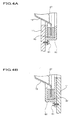
- Figs 4A and 4B are enlarged cross-sectional views showing a feature of an embodiment of a structure around a speaker unit according to the present invention having a "fitting structure as a part before assembly having a J-, U-, or h-shaped cross section.”
- a speaker unit is fixed from this side of a baffle board 11.
- a speaker unit is fixed from the back of the baffle board 11.
- a fitting guide 62 with a concave portion having a J-, U-, or h-shaped cross section which can house a frame 15 with room outside the edge of the frame 15 is fixed to the fringe of a hole made in the baffle board 11 with a screw 61.
- a vibration absorbing member 20 is fitted into the concave portion of the fitting guide 62.
- the vibration absorbing member 20 is located so as to cover the edge portion of the frame 15.
- the frame 15 is attached flexibly to the baffle board 11 with the vibration absorbing member 20 so that the frame 15 can move freely in the direction in which the cone paper 27 vibrates with strokes being much the same as the amplitude of the vibrations of the cone paper 27.
- Fig. 5A shows a vibration absorbing member substantially the same as that shown in Fig. 3A
- Fig. 5B is a cross-sectional view showing an embodiment of a structure around a speaker unit according to the present invention which includes not only the “basic” structure shown in Fig. 1 but also a "supporting structure in which a rear magnet is loosely fitted into a concave portion with a vibration absorbing member between" for supporting the weight of the rear magnet.
- the edge portion of a frame 80 is attached flexibly to the fringe of a hole made in a baffle board 11 with vibration absorbing members 17 and 18 so that the frame 80 can move freely with strokes of 1 millimeter or more in the direction in which a cone paper 27 vibrates.
- This attachment form is much the same as that shown in Fig. 1. Therefore, descriptions of a prop 3 and a structure around it will be omitted.
- the vibration absorbing members 17 and 18 are located between a position regulating member 50 and the baffle board 11 with the edge portion of the frame 80 between.
- a supporting base 70 has a fitting guide 73 with a concave portion on it.
- a large magnet 72 connected inseparably to the frame 80 is supported by the fitting guide 73 with a vibration absorbing member 41 in the concave portion between.
- a resonance box is not used and a light baffle board not fixed firmly is used.
- a vibration absorbing structures to a speaker unit with a conventional resonance box and a heavy baffle board fixed firmly to the resonance box will give interesting results. That is to say, clearer reproduced sounds are obtained.
- Fig. 6 is a cross-sectional view showing an embodiment of a structure around a speaker unit according to the present invention applied to a pillow, being a piece of bedding, in which the "basic" structure shown in Fig. 1 is used and a baffle board is utilized as a back sound screening board.
- An L-channel dedicated first baffle board 11 with a speaker unit 1 for outputting L-channel sounds on it and an R-channel dedicated second baffle board 12 with a speaker unit 2 for outputting R-channel sounds on it are joined to a first backboard 13 and a second backboard 14 at their edges respectively so that these baffle boards face a listener's ears at a proper angle and distance.
- These L- and R-channel sounds produce a stereophonic effect.
- the L- and R-channel components form a unitary structure.
- the first backboard 13 and the second backboard 14 may be regarded as extensions to the first baffle board 11 and the second baffle board 12 respectively.
- a frame 15 of the speaker unit 1 and the first baffle board 11 are joined with a vibration absorbing member 17 of urethane foam (sponge) between.
- a frame 16 of the speaker unit 2 and the second baffle board 12 are joined with a vibration absorbing member 18 of urethane foam (sponge) between.
- the first backboard 13 and the second backboard 14 are joined with a vibration absorbing member 19 of urethane foam (sponge) between.
- An elastic joining member 7 of chloroethylene is attached to a joint formed by the first backboard 13 and the second backboard 14 with moderate elasticity maintained in order to strengthen the joint.
- L-channel sound waves 5 and 5' with phases opposite to each other are radiated from the L-channel dedicated speaker unit 1 in the forward and backward directions respectively.
- the sound wave 5 in front of the baffle board 11 is isolated to some extent from the sound wave 5' behind the baffle board 11 by the baffle board 11, so these sound waves will not cancel out each other by addition.
- the area of the first baffle board 11 is finite and some of the sound wave 5' will travel to the front of the first baffle board 11 around its edge.
- the pillow material 9 functions as a sound absorbing material and absorbs the sound wave 5' which travels to the front of the first baffle board 11.
- most of the sound wave 5' will be absorbed before it can reach an ear 29. That is to say, the sound wave 5' almost never interferes with the sound wave 5. Therefore, low-pitched sounds included in the sound wave 5 almost never attenuate.
- the distance between the L-channel dedicated speaker unit 1 and the ear 29 is short, so the sound wave 5, being direct sounds, almost never attenuates. As a result, the original sound will be reproduced with high fidelity.
- the type of the pillow material 9 described later has a great influence on effect as a direct sound transmitting section and valid direct sounds almost never attenuate.
- the pillow material 9 functions as a sound absorbing material and absorbs a sound wave 6' which travels to the front of the second baffle board 12 around its edge. That is to say, the sound wave 6' almost never interferes with a sound wave 6. As a result, low-pitched sounds included in the sound wave 6, being direct sounds, almost never attenuate.
- the first baffle board 11 and the second baffle board 12 are far smaller and lighter than one used in the above conventional speaker. Therefore, if vibrations are transmitted from the speaker unit 1 to the first baffle board 11 via the frame 15 and from the speaker unit 2 to the second baffle board 12 via the frame 16, they may have the bad influence of mutual interference on the first baffle board 11 and the second baffle board 12.
- the vibration absorbing members 17, 18, and 19 and the elastic joining member 7 prevent these vibrations from being transmitted. As a result, sound waves which will ruin a stereophonic effect are screened out by these members.
- the vibration absorbing members 17, 18, and 19 and the elastic joining member 7 absorb sound waves at audio frequencies . Furthermore, the vibration absorbing member 17 connects the frame 15 and the first baffle board 11 so that they become stable. Similarly, the vibration absorbing member 18 connects the frame 16 and the second baffle board 12 so that they become stable. The vibration absorbing member 19 and the elastic j joining member 7 connect the first backboard 13 and the second backboard 14 so that they become stable.
- a mesh protective net 8 is located in front of and behind the speaker units 1 and 2 (mesh protective nets located behind them are not shown) so that buckwheat chaff does not get into the speaker units 1 and 2.
- Air-permeable cloth which does not screen out sound waves is suitable for the outside member (outside bag) 10 of a pillow.
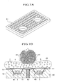
- Fig. 7A shows a back sound screening board, in which a bag sealing liquid or gel is provided with constrictions and an irregular surface is formed by a recess-shaped or wave-shaped unevenness due to the constrictions, and it can be applicable as a baffle board 11 shown in the other figures.
- the baffle board 11 When using as the baffle board 11, the mounting structure of the speaker unit have to be slightly modified, however, details thereof will be omitted.
- Fig. 7B is a cross-sectional view showing an embodiment of a structure around a speaker unit according to the present invention applied to a pillow, being a piece of bedding, in which the "embedded-type" structure shown in Fig. 2 is used and a sound absorbing material being able to maintain its shape is also utilized as material for a pillow.
- Conic cavities 41 and 42 are formed on the top of a member 40 of fibers having great elasticity and air-permeability, being a base for a pillow.
- An L-channel dedicated speaker unit 1 and an R-channel dedicated speaker unit 2 are fitted upward into the cavities 41 and 42 respectively.
- the speaker units 1 and 2 are covered with a protective net 8 in order to protect cone papers in them.
- the protective net 8 is completely covered with a pillow material 9.
- a back sound screening board 51 consisting of a rubber mat with a thickness of about 3 millimeters is laid instead of a baffle board in order to obtain the effect of screening out back sounds.
- An LR partition wall 52 is formed by injecting a waterproof resin (it is preferable to use a waterproof material) into the central portion of the member 40.
- a waterproof resin it is preferable to use a waterproof material
- this waterproof resin is injected into target places with a dedicated injector when waterproofing work is done on a bathroom, a kitchen, or the like.
- a silicone resin for example, an elastic partition wall will be formed. This improves the effect of separating the L-channel and the R-channel and heightens stereo sound effects according to the present invention.
- Short tubes of hard resin that is to say, hard resin tubes of a high molecular compound, such as polypropylene, with an outside diameter of 8 millimeters, a thickness of 1 millimeter, and a length of 10 millimeters which are not crushed between finger and thumb are suitable for the pillow material 9. They are suitable for a pillow itself and clear sounds can be obtained by the use of them. They are sold at a bedding store.
- the pillow material 9 is dispersed within a pillow and each of mesh bags properly divided contains part of it.
- the above hard resin tubes used in the above direct sound transmitting section are considered from their shape to form a cushion material which is hard to attenuate at least direct sounds. Therefore, if material other than the above hard resin tubes, such as sponge or cottonlike material, is used as a cushion material, necessary direct sounds will attenuate. The above buckwheat chaff, too, did not give good results.
- Indirect sounds with a phase opposite to that of direct sounds generated behind the cone paper 27 can be considered from the shape of material used in the back sound screening section to cancel out each other while they repeat irregular reflection within Curllock described above. By considering so, its fine sound effects can be explained.
- the short tubes of hard resin produce the best sound effects, so they must be located directly over and near the protective net 8. Comfortableness, design, costs, and the like only as a pillow are thoroughly pursued for the other portions and the pillow material 9 is arranged in the best way.
- the pillow material 9 can be arranged freely on the basis of the dividing shape (not shown) of the above mesh bags.
- short tubes of soft polyethylene can be added only to the portion where the nape of a user touches to raise its height. This will heighten the added value of the goods and provide the advantage of product differentiation, resulting in a larger sale.
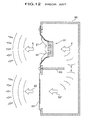
- Fig. 8 shows an embodiment of a hanging back sound screening board according to the present invention.
- a hanging back sound screening board 83 is applied to a speaker including a baffle board 86 hanging from a pole 87.
- a frame 85 holds the edge of a cone paper 27 of the speaker so that the cone paper 27 can vibrate freely in the forward and backward directions.
- the frame 85 is also held to the baffle board 86 so that it can vibrate freely in the forward and backward directions.
- the back sound screening board 83 is located at both sides of the cone paper 27 and the baffle board 86 nearly on a plane extending from them so that space in front of them is isolated from space behind them.
- the baffle board 86 also functions as a back sound screening board, but it is not called a back sound screening board for convenience of an explanation for Fig. 8.
- the "back sound screening board” can be considered as an “acoustic resonance reflecting board,” because it also functions as “passive radiator,” that is to say, as a sound source. This is one of the two basic principles of the present invention, so this applies to all the embodiments shown in Figs. 1 through 10.
- the cone paper 27 of a speaker has an "active radiation function," while the back sound screening board has “the function of radiating passive resonances set up by the cone paper 27 in cooperation with the cone paper 27.” This is why the back sound screening board can be considered as an acoustic resonance reflecting board.
- the back sound screening board (hereinafter also referred to as a "passive radiator” or “acoustic resonance reflecting board”) 83 is faced almost squarely to a listener. That is to say, even if the back sound screening board 83 is a speaker itself, the listener can listen to sound which comes directly from the back sound screening board 83.
- Tests for checking the effect of the back sound screening board 83 showed that the existence of the back sound screening board 83 clearly turns up sound volume to a listener.
- the size of the baffle board 86 (about 60 centimeters in width) with a thickness of about 4 millimeters were located at both sides of the baffle board 86 at the same short distance from the baffle board 86, the best sound effects were obtained.
- the distance between the cone paper 27 located in the middle of the baffle board 86 and the far end of one back sound screening board 83 is 1 meter or less and the total width is 2 meters or less.
- the total width is 3 meters or less.
- baffle board 86 Most types of rigid boards will have the same effect as the baffle board 86, but corrugated cardboard has no effect.
- the relative positions of the L-channel dedicated speaker, the R-channel dedicated speaker, and a listener should form a regular triangle. Sufficient space between the L-channel dedicated speaker and the R-channel dedicated speaker is ideal for a good stereophonic effect.
- the reflection function of the back sound screening board (acoustic resonance reflecting board) 83 described above will be the same as the effect of a reflecting board used in an electric illuminator. That is to say, as a searchlight or headlight cannot be made without a reflecting board, the force of a limited energy source is delivered efficiently to a target.
- the back sound screening board 83 delivers sound waves efficiently to a listener who is directly in front of a speaker, being a sound source. In practice, however, this has almost never been studied. Therefore, an embodiment which gave the best results will now be shown.
- the fidelity and loudness of sound reproduced by a small-sized low-output speaker are equal to those of sound reproduced by a large-sized high-output speaker. Therefore, a speaker with the same performance as a conventional one can be priced down, of course.
- High-fidelity reproduced sounds which were obtained by a conventional stereo speaker with a resonance box and a high-output amplifier at an expense of 500, 000 yen can be realized by a simple small-sized low-output speaker at an expense of only tens of thousands of yen.
- an efficient acoustic apparatus being able to minimize the attenuation of sound even in a listening room the sound absorbing structure of which is not desirable in terms of sound effects can be provided.
- An example of such a room is a Japanese-style room (not shown) with a closet for housing futons.
- This means for connecting the frame 85 and the baffle board 86 flexibly is the same as those shown in Figs. 1 through 5.
- the effect of the back sound screening board 83 according to the present invention can be maximized by the use of this means.
- Fig. 9 shows an embodiment of a back sound screening board of a folding screen type according to the present invention.
- a back sound screening board 97 shown in Fig. 9 is located at both sides of a baffle board 99 and is supported with the baffle board 99 by the use of an oilless resin hinge 98 so that the back sound screening board 97 can be freely folded like a flap.
- the back sound screening boards 97 of a foamed chloroethylene board the size of the baffle board 99 with a thickness of about 4 millimeters were located at both sides of the baffle board 99 at the same obtuse angle to the baffle board 99, the best sound effects were obtained. In a word, the back sound screening boards 97 should be located at right angles to a listener.
- the total width is the same with the embodiment shown in Fig. 8.
- AV equipment should basically form comfortable living space, but in reality there are many cases where AV equipment limits human living space. In order to solve such a situation, it is urgent that the present invention should be applied. That is to say, graceful AV equipment of the vertical flat board type design used in the near future should be manufactured as goods and be spread.
- a "dedicated software replay equipment for producing a synergistic effect between images and stereophony” sold under the name of "AV Surround,” “Home Theater,” or the like is attracting many people's interest now, but it is not very widespread. If speaker systems of the vertical flat board type design and low-cost AV equipment are adopted, the spread of the dedicated software replay equipment will be promoted. This contributes toward the development of the AV-related equipment and software industries in cooperation with the BS digital broadcasting started as commercial broadcasting and Internet delivery of television programs.
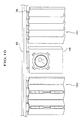
- Fig. 10 shows an embodiment of a foldable back sound screening board of an "accordion curtain type” or “slide shutter type” according to the present invention.
- a lightweight back sound screening board being foldable like an accordion curtain (hereinafter also referred to as the "accordion curtain") 100 consists of long and narrow resin boards with a thickness of between about 3 and 10 millimeters and a width of about 10 centimeters which are connected by hinges.
- the back sound screening board 100 is hung from a head jamb 85 by sliding metal fittings 78 so that the back sound screening board 100 can slide freely on a rail of the head jamb 85.
- the back sound screening board 100 is a fitting for partitioning a room which can be opened and closed freely.
- the accordion curtain 100 is located with both sides (only the left-hand side in Fig. 10) of a baffle board 86 as doors so that it can be opened and closed freely.
- the area of the accordion curtain 100 and the relative positions of the accordion curtain 100 and the baffle board 86 should be optimized with fittings inside a room where the accordion curtain 100 is to be located taken into consideration.
- the accordion curtain 100 may be left open at need.
- Aback sound screening board 101 located on the right-hand side of the baffle board 86 shown in Fig. 10 which can be folded freely like a slide shutter (hereinafter also referred to as the "slide shutter") also consists of long and narrow boards with a thickness of between about 3 and 10 millimeters and a width of about 10 centimeters which are not connected by hinges.
- the back sound screening board 101 is hung from the head jamb 85 by the sliding metal fittings 78 so that the back sound screening board 101 can slide freely on the rail of the head jamb 85 and therefore expand and overlap freely like a blind which opens and closes horizontally.
- the back sound screening board 101 is a fitting for partitioning a room which can be opened and closed freely.
- the back sound screening board 101 may be left open at need. This is the same with the accordion curtain 100.
- Fig. 13 shows a first embodiment of the present invention by way of design drawing, in which Fig. 13A is a front view, Fig. 13B is a sectional view taken along the line A-A of Fig. 13A, and Fig. 13C is an exploded sectional view thereof.
- a punching board, decorative wire mesh, top grille (protection net with a frame) 88 or the like may have a function to keep the profile as well as protecting the cone paper 27.
- the back sound screening board 51a made of a mat with a hole portion, which mainly consists of a bag sealing therein gel, is employed.
- Fig. 13 shows only one speaker unit 13, however, a plurality of units may be used for obtaining a stereo effect.
- the rear cover 89 may be made from the same material as that introduced with reference to Fig. 13C, and is made of a punching board, decorative wire mesh or the like, so as to keep a certain outer profile and to support the whole mounting structure. When mounting on a flat wall by directly contacting the wall, the rear cover 89 may be a cheap sheet metal or veneer plate, regardless of the air permeability of the rear cover 89.
- Fig. 14 shows a second embodiment of the present invention by way of design drawing, in which Fig. 14A shows a front view and a vertical sectional view taken along the line B-B, and Fig. 14B is a transverse sectional view taken along the line C-C of Fig. 14A.
- the Curllock member 40b has substantially trapezoidal section, and its front projection is covered, from the front part, with the back sound screening board 51b made by a mat with a hole portion mainly consisting gel.
- a punching board, decorative wire mesh, top grille 88a or the like is omitted from Fig. 14A. The same can be said to Figs. 15 and 16.
- the back sound screening board 51b surrounds the front part of the speaker unit (as a sound source) with a trough-shaped curved surface, and the front and rear of the speaker unit 1 is effectively and separately shut out. Therefore, the object of the present invention can be achieved by an area smaller than the back sound screening board 51a formed by a flat plate, and pure and clear sound can be obtained by a small and compact structure.
- Fig. 15 shows a third embodiment of the present invention by way of design drawing, in which Fig. 15A is a front view, and Fig. 15B is a sectional view taken along the line D-D of Fig. 15A.
- the Curllock member 40c has substantially trapezoidal section, and the center portion of its top surface is provided with a conical hole for the insertion of the speaker unit 1.
- the back sound screening board 51c has a trapezoidal shape, and the bottom surface thereof is provided with a circular hole so as to surround the speaker unit 1 from the front part.
- the front and rear of the speaker unit 1 is effectively and separately shut out by the back sound screening board 51c. Therefore, the object of the present invention can be achieved by an area smaller than the back sound screening board 51a formed by a flat plate, and pure and clear sound can be obtained by a small and compact structure.
- Fig. 16 shows a fourth embodiment of the present invention by way of design drawing, in which Fig. 16A is a front view, and Fig. 16B is a sectional view taken along the line E-E of Fig. 16A.
- the Curllock member 40d has substantially trapezoidal section, and the center portion of its top surface is provided with a conical hole for the insertion of the speaker unit 1.
- the back sound screening board 51d has a trapezoidal shape, and the bottom surface thereof is provided with a circular hole so as to surround the speaker unit 1 from the front part.
- the front and rear of the speaker unit 1 is effectively and separately shut out by the back sound screening board 51d. Therefore, the object of the present invention can be achieved by an area smaller than the back sound screening board 51a formed by a flat plate, and pure and clear sound can be obtained by a small and compact structure.
Landscapes
- Physics & Mathematics (AREA)
- Engineering & Computer Science (AREA)
- Acoustics & Sound (AREA)
- Signal Processing (AREA)
- Details Of Audible-Bandwidth Transducers (AREA)
- Obtaining Desirable Characteristics In Audible-Bandwidth Transducers (AREA)
Applications Claiming Priority (6)
| Application Number | Priority Date | Filing Date | Title |
|---|---|---|---|
| JP2000241992 | 2000-08-10 | ||
| JP2000241993 | 2000-08-10 | ||
| JP2000241992 | 2000-08-10 | ||
| JP2000241993 | 2000-08-10 | ||
| JP2001006221 | 2001-01-15 | ||
| JP2001006221 | 2001-01-15 |
Publications (3)
| Publication Number | Publication Date |
|---|---|
| EP1179968A2 true EP1179968A2 (fr) | 2002-02-13 |
| EP1179968A3 EP1179968A3 (fr) | 2004-12-15 |
| EP1179968B1 EP1179968B1 (fr) | 2009-03-11 |
Family
ID=27344312
Family Applications (1)
| Application Number | Title | Priority Date | Filing Date |
|---|---|---|---|
| EP01306597A Expired - Lifetime EP1179968B1 (fr) | 2000-08-10 | 2001-08-01 | Structure autour d'un haut-parleur |
Country Status (3)
| Country | Link |
|---|---|
| US (2) | US6904157B2 (fr) |
| EP (1) | EP1179968B1 (fr) |
| DE (1) | DE60137888D1 (fr) |
Cited By (7)
| Publication number | Priority date | Publication date | Assignee | Title |
|---|---|---|---|---|
| EP1505851A1 (fr) * | 2003-08-06 | 2005-02-09 | Vestel Elektronik Sanayi ve Ticaret A.S. | Dispositif de fixation pour un générateur de son |
| CN102625204A (zh) * | 2011-01-28 | 2012-08-01 | 索尼公司 | 耳垫 |
| EP2690888A3 (fr) * | 2012-07-25 | 2014-03-19 | Shima System Co., Ltd. | Unité d'haut-parleur comme produit encaissé |
| WO2016022238A1 (fr) * | 2014-08-07 | 2016-02-11 | Bose Corporation | Repose-tête avec haut-parleurs et procédé de fabrication d'un élément de coussin de repose-tête |
| CN107948783A (zh) * | 2016-10-12 | 2018-04-20 | 铁三角有限公司 | 头戴式耳机 |
| WO2019214868A1 (fr) * | 2018-05-07 | 2019-11-14 | Gefion Records Aps | Agencement de haut-parleur et procédé de fourniture de l'agencement de haut-parleur |
| GB2606586A (en) * | 2021-06-21 | 2022-11-16 | Stratton Acoustics Ltd | A speaker unit |
Families Citing this family (63)
| Publication number | Priority date | Publication date | Assignee | Title |
|---|---|---|---|---|
| US7073624B2 (en) * | 2002-07-31 | 2006-07-11 | Harman International Industries, Incorporated | Loudspeaker baffle isolation system |
| JP4443104B2 (ja) * | 2002-11-18 | 2010-03-31 | 株式会社ユニバーサルエンターテインメント | 遊技機 |
| US9949004B2 (en) * | 2003-03-10 | 2018-04-17 | Daniel E. Cohen | Sound and vibration transmission device |
| WO2005117647A1 (fr) | 2004-05-28 | 2005-12-15 | Wms Gaming Inc. | Dispositif de jeu avec chaise a capacite audio rattachee |
| WO2005117649A1 (fr) * | 2004-05-28 | 2005-12-15 | Wms Gaming Inc. | Dispositif d'assemblage de chaise pour appareil de jeux |
| US20060008109A1 (en) * | 2004-07-07 | 2006-01-12 | Huang Maurice R | Loudspeaker structure |
| WO2006029378A2 (fr) | 2004-09-09 | 2006-03-16 | Guenther Godehard A | Haut-parleurs et systemes |
| JP2006229517A (ja) * | 2005-02-17 | 2006-08-31 | Pioneer Electronic Corp | スピーカー装置用のフレーム及びスピーカー装置 |
| JP4594127B2 (ja) * | 2005-02-17 | 2010-12-08 | パイオニア株式会社 | スピーカー装置用のフレーム及びスピーカー装置 |
| JP4764062B2 (ja) * | 2005-04-28 | 2011-08-31 | 株式会社東芝 | 電子機器 |
| US20060291689A1 (en) * | 2005-06-07 | 2006-12-28 | Ms. Yen-Chen Chan | Surround for speaker |
| US7571503B2 (en) * | 2005-09-15 | 2009-08-11 | Metric Products, Inc. | Headphone pillow |
| US7587772B2 (en) * | 2005-10-07 | 2009-09-15 | Ward Deborah | Infant nesting device |
| US8041048B2 (en) * | 2008-12-31 | 2011-10-18 | Youngtack Shim | Electromagnetically-countered speaker systems and methods |
| TWI328402B (en) * | 2007-01-12 | 2010-08-01 | Asustek Comp Inc | Sound broadcasting mechanism and electric device using the same |
| JP4722878B2 (ja) * | 2007-04-19 | 2011-07-13 | ソニー株式会社 | ノイズ低減装置および音響再生装置 |
| US8189840B2 (en) | 2007-05-23 | 2012-05-29 | Soundmatters International, Inc. | Loudspeaker and electronic devices incorporating same |
| JP4396739B2 (ja) * | 2007-07-25 | 2010-01-13 | ソニー株式会社 | 情報伝達方法、情報伝達システム、情報受信装置及び情報送信装置 |
| CN101547385A (zh) * | 2008-03-24 | 2009-09-30 | 鸿富锦精密工业(深圳)有限公司 | 减振装置及使用该减振装置的音频设备 |
| TWI330231B (en) * | 2008-03-26 | 2010-09-11 | Pegatron Corp | Damper and fastening device using the same |
| JP2009260524A (ja) * | 2008-04-15 | 2009-11-05 | Sony Corp | スピーカー装置 |
| US8155368B2 (en) * | 2008-04-30 | 2012-04-10 | George Cheung | Shoulder/neck supporting electronic application |
| CN101594562B (zh) * | 2008-05-30 | 2013-09-04 | 深圳富泰宏精密工业有限公司 | 便携式电子装置 |
| TWI454123B (zh) * | 2008-07-04 | 2014-09-21 | Chi Mei Comm Systems Inc | 可攜式電子裝置 |
| CN102326196A (zh) * | 2009-02-20 | 2012-01-18 | 日东纺音响工程株式会社 | 声响产生系统、声响收录系统、声响产生方法、声响收录方法、声响调整方法、声响调整程序、声场调整系统、扬声器基座、家具、扬声器箱以及扬声器装置 |
| JPWO2011074225A1 (ja) * | 2009-12-14 | 2013-04-25 | パナソニック株式会社 | スピーカ保持機構およびそれを備えたテレビジョン受像機 |
| US8290195B2 (en) | 2010-03-31 | 2012-10-16 | Bose Corporation | Acoustic radiation pattern adjusting |
| JP2013095312A (ja) * | 2011-11-02 | 2013-05-20 | Alpine Electronics Inc | 車載音響装置およびその組立て方法 |
| US20140064541A1 (en) * | 2012-08-31 | 2014-03-06 | Dr. G Licensing, Llc | Wrist Band and Other Portable Loudspeakers and Electronic Apparatus Utilizing Same |
| US9088842B2 (en) | 2013-03-13 | 2015-07-21 | Bose Corporation | Grille for electroacoustic transducer |
| US20140286011A1 (en) * | 2013-03-14 | 2014-09-25 | Aliphcom | Combination speaker and light source powered using light socket |
| US9327628B2 (en) | 2013-05-31 | 2016-05-03 | Bose Corporation | Automobile headrest |
| JP2016534645A (ja) * | 2013-08-28 | 2016-11-04 | サブパック・インコーポレイテッドSubpac, Inc. | 多段触覚音響装置 |
| US9699537B2 (en) | 2014-01-14 | 2017-07-04 | Bose Corporation | Vehicle headrest with speakers |
| CN104144364B (zh) * | 2014-06-05 | 2018-10-12 | 沈文贤 | 多功能迷你音箱架 |
| JP6329018B2 (ja) * | 2014-06-27 | 2018-05-23 | クラリオン株式会社 | ヘッドレスト装置 |
| JP6440998B2 (ja) * | 2014-08-25 | 2018-12-19 | 株式会社タチエス | ヘッドレスト及び車両用シート |
| US9440566B2 (en) | 2014-12-05 | 2016-09-13 | Bose Corporation | Lightweight acoustic enclosures |
| WO2016151022A1 (fr) * | 2015-03-23 | 2016-09-29 | Johnson Controls Gmbh | Procédé de fabrication d'un appui-tête pourvu d'un module fonctionnel intégré |
| DK3089477T3 (en) * | 2015-04-28 | 2018-09-17 | L Acoustics Uk Ltd | AN APPARATUS FOR REPRESENTING A MULTI CHANNEL SIGNAL AND A METHOD FOR MAKING A MULTI CHANNEL SIGNAL |
| US9776543B2 (en) | 2016-01-25 | 2017-10-03 | Ford Global Technologies, Llc | Integrated independent thigh supports |
| US10035442B2 (en) | 2016-01-25 | 2018-07-31 | Ford Global Technologies, Llc | Adjustable upper seatback module |
| US9756408B2 (en) * | 2016-01-25 | 2017-09-05 | Ford Global Technologies, Llc | Integrated sound system |
| US10052990B2 (en) | 2016-01-25 | 2018-08-21 | Ford Global Technologies, Llc | Extended seatback module head restraint attachment |
| CN105812966A (zh) * | 2016-03-10 | 2016-07-27 | 长沙待电子科技有限公司 | 集成吊顶音箱结构和集成吊顶音箱 |
| US10239432B2 (en) * | 2016-03-17 | 2019-03-26 | Bose Corporation | Acoustic output through headrest wings |
| CN106101924B (zh) * | 2016-06-21 | 2022-07-15 | 杭州鸿雁电器有限公司 | 一种可防水音频传输装置和室内音频播放系统 |
| CN111586540A (zh) * | 2017-08-29 | 2020-08-25 | 张琴 | 一种移动终端的扬声器组件 |
| CN108682203A (zh) * | 2018-05-15 | 2018-10-19 | 郑州小夫子文化传媒有限公司 | 一种用于国学机的智能播放系统 |
| US11843359B2 (en) * | 2018-06-28 | 2023-12-12 | Kurt P Hahn | Amplification system and method |
| WO2020111118A1 (fr) | 2018-11-29 | 2020-06-04 | テイ・エス テック株式会社 | Système de siège et dispositif d'expérience de siège |
| WO2020122135A1 (fr) * | 2018-12-13 | 2020-06-18 | テイ・エス テック株式会社 | Capteur biologique et siège de véhicule |
| US10694273B1 (en) * | 2019-02-22 | 2020-06-23 | Avaya, Inc. | Clip based speaker retention to a mounting surface |
| GB201907267D0 (en) * | 2019-05-23 | 2019-07-10 | Pss Belgium Nv | Loudspeaker |
| CN110381414A (zh) * | 2019-08-09 | 2019-10-25 | 陈国富 | 具有高声阻箱体及电感电容缓冲电路的高保真度音箱 |
| CN110475185B (zh) * | 2019-08-13 | 2021-05-25 | 海能达通信股份有限公司 | 声学辐射组件以及发声设备 |
| FR3109754B1 (fr) * | 2020-04-29 | 2022-05-13 | Faurecia Sieges Dautomobile | Appui-tête pour siège de véhicule et siège associé |
| GB202008724D0 (en) * | 2020-06-09 | 2020-07-22 | Pss Belgium Nv | Headrest mounted loudspeaker for producing sound at base frequencies |
| US11330364B1 (en) * | 2021-01-12 | 2022-05-10 | Robert Bosch Gmbh | Ported speaker assembly |
| WO2022180913A1 (fr) | 2021-02-25 | 2022-09-01 | パナソニックIpマネジメント株式会社 | Dispositif électrique |
| US12604136B2 (en) * | 2021-08-12 | 2026-04-14 | Boe Technology Group Co., Ltd. | Assembled screen unit and display module |
| KR102744689B1 (ko) * | 2023-11-24 | 2024-12-19 | 케이지모빌리티 주식회사 | 차량용 탈,부착식 랜턴 겸용 블루투스 스피커 장치 |
| WO2025122647A1 (fr) * | 2023-12-05 | 2025-06-12 | Sundance Spas, Inc. | Système de haut-parleur pour spas |
Family Cites Families (37)
| Publication number | Priority date | Publication date | Assignee | Title |
|---|---|---|---|---|
| US3135349A (en) * | 1962-04-02 | 1964-06-02 | Uolevi L Lahti | Loudspeaker |
| US3290450A (en) * | 1962-12-21 | 1966-12-06 | Majoros Barna | Pillow type speaker support |
| US3384719A (en) * | 1964-10-21 | 1968-05-21 | Gen Electric | Stereophonic speaker arrangement |
| US3412824A (en) * | 1967-02-17 | 1968-11-26 | James C. Armstrong | Speaker cabinet enclosure |
| US3430728A (en) * | 1968-03-27 | 1969-03-04 | William S Dunning | Loudspeaker assembly with loudspeaker supported by vibratory diaphragm |
| US3870834A (en) | 1973-06-11 | 1975-03-11 | Yeaple Corp | Personal stereophonic speaker system |
| US3909531A (en) * | 1974-03-25 | 1975-09-30 | Custom Electronics Inc | Acoustic transducer system |
| US3993345A (en) * | 1975-10-29 | 1976-11-23 | Acoustic Fiber Sound Systems, Inc. | Enclosure for automobile trunk-mounted loudspeaker |
| US4038499A (en) * | 1976-02-02 | 1977-07-26 | Yeaple Corporation | Stereophonic pillow speaker system |
| SE447780B (sv) | 1981-11-26 | 1986-12-08 | Stig Carlsson | Hogtalare med en ljudabsorbent |
| US4433749A (en) * | 1982-02-19 | 1984-02-28 | Watkins William H | Acoustic rear radiation absorption for loudspeaker systems |
| GB2132853A (en) | 1982-09-07 | 1984-07-11 | Andrew Jones | Loudspeaker enclosure |
| US4598178A (en) * | 1983-12-16 | 1986-07-01 | Rollins William L | Means for critically damping a dynamic loudspeaker |
| SE445162B (sv) | 1984-10-12 | 1986-06-02 | Ericsson Telefon Ab L M | Anordning for fasthallning, akustisk tetning och vibrationsisolering av en elektroakustisk omvandlare i ett apparatholje |
| US4638884A (en) | 1985-07-11 | 1987-01-27 | Willis S. Cole | Chambered headrest mounting for stereophonic loudspeakers |
| EP0249428A3 (fr) | 1986-06-10 | 1989-04-05 | Tai-Cal Enterprises | Oreiller portable à haut-parleurs stéréophoniques, auto-alimenté |
| US5192761A (en) * | 1988-07-27 | 1993-03-09 | North Carolina Central Univ. | 1,2,4-triazolidine-3,5-diones and 1,3,5-triazine-2,4(1-H,3H)-diones, pharmaceutical compositions |
| JP2684690B2 (ja) | 1988-07-29 | 1997-12-03 | 藤森工業株式会社 | 床 材 |
| CA2049526A1 (fr) * | 1991-08-20 | 1993-02-21 | Chester Albert | Coussin orthopedique avec hauts-parleurs |
| FR2713868B1 (fr) * | 1993-12-13 | 1997-05-09 | Paul Lancon | Tétière ou appuie-tête comprenant une sonorisation individuelle de proximité. |
| US5526162A (en) | 1994-09-27 | 1996-06-11 | At&T Corp. | Synchronous polarization and phase modulation for improved performance of optical transmission systems |
| US6310709B1 (en) | 1995-12-29 | 2001-10-30 | Tyco Submarine Systems Ltd. | Synchronous polarization and phase modulation using a periodic waveform with complex harmonics for improved performance of optical transmission systems |
| US5739481A (en) | 1996-05-17 | 1998-04-14 | Lucent Technologies Inc. | Speaker mounting system |
| US5966206A (en) | 1996-10-10 | 1999-10-12 | Tyco Submarine Systems Ltd. | Interlocked high power fiber system using OTDR |
| US5764405A (en) | 1996-10-10 | 1998-06-09 | Tyco Submarine Systems Ltd. | Lossless optical transmission system architecture with non-failing optical amplifiers |
| US6014479A (en) | 1996-10-10 | 2000-01-11 | Tyco Submarine Systems Ltd. | High channel density wavelength division multiplex (WDM) optical transmission system and method with negligible four-wave mixing (FWM) penalty |
| GB9625322D0 (en) | 1996-12-05 | 1997-01-22 | Raychem Ltd | Acoustic isolation of vibration transducer |
| US5946119A (en) | 1997-02-12 | 1999-08-31 | Tyco Submarine Systems Ltd. | Wavelength division multiplexed system employing optimal channel modulation |
| US5938309A (en) | 1997-03-18 | 1999-08-17 | Ciena Corporation | Bit-rate transparent WDM optical communication system with remodulators |
| DE29716471U1 (de) | 1997-09-15 | 1998-07-30 | Lien, Kin-Lung, Taipeh/T'ai-pei | Versteckbare Klangvorrichtung |
| US5912761A (en) | 1998-01-22 | 1999-06-15 | Tyco Submarine Systems Ltd. | Apparatus and method for controlling shared optical pump power sources |
| US6304351B1 (en) | 1998-10-28 | 2001-10-16 | Tycom (Us) Inc. | Universal branching unit |
| US6327250B1 (en) | 1998-12-21 | 2001-12-04 | Tycom (Us) Inc. | Method and apparatus for supressing crosstalk between data and monitoring channel in an optical communication system |
| US6147796A (en) | 1999-01-12 | 2000-11-14 | Tyco Submarine Systems Ltd. | Method for determining transmission parameters for the data channels of a WDM optical communication system |
| US6258438B1 (en) * | 1999-06-17 | 2001-07-10 | Daimlerchrysler Corporation | Vehicle shelf trim panel with insert molded speaker grille |
| US6341023B1 (en) | 1999-07-23 | 2002-01-22 | Tycom (Us) Inc. | Multiple level modulation in a wavelength-division multiplexing (WDM) systems |
| US6338395B1 (en) * | 1999-09-29 | 2002-01-15 | P.T. Hartono Istana Electronics | Kapok loudspeaker enclosure damping material |
-
2001
- 2001-07-31 US US09/917,717 patent/US6904157B2/en not_active Expired - Fee Related
- 2001-08-01 EP EP01306597A patent/EP1179968B1/fr not_active Expired - Lifetime
- 2001-08-01 DE DE60137888T patent/DE60137888D1/de not_active Expired - Lifetime
-
2004
- 2004-07-19 US US10/893,340 patent/US7162048B2/en not_active Expired - Fee Related
Cited By (11)
| Publication number | Priority date | Publication date | Assignee | Title |
|---|---|---|---|---|
| EP1505851A1 (fr) * | 2003-08-06 | 2005-02-09 | Vestel Elektronik Sanayi ve Ticaret A.S. | Dispositif de fixation pour un générateur de son |
| CN102625204A (zh) * | 2011-01-28 | 2012-08-01 | 索尼公司 | 耳垫 |
| EP2690888A3 (fr) * | 2012-07-25 | 2014-03-19 | Shima System Co., Ltd. | Unité d'haut-parleur comme produit encaissé |
| WO2016022238A1 (fr) * | 2014-08-07 | 2016-02-11 | Bose Corporation | Repose-tête avec haut-parleurs et procédé de fabrication d'un élément de coussin de repose-tête |
| US9428090B2 (en) | 2014-08-07 | 2016-08-30 | Bose Corporation | Headrest with speakers and method for manufacturing headrest cushion member |
| CN107948783A (zh) * | 2016-10-12 | 2018-04-20 | 铁三角有限公司 | 头戴式耳机 |
| US10687133B2 (en) | 2016-10-12 | 2020-06-16 | Audio-Technica Corporation | Headphone |
| EP3310073B1 (fr) * | 2016-10-12 | 2024-01-24 | Audio-Technica Corporation | Casque audio |
| WO2019214868A1 (fr) * | 2018-05-07 | 2019-11-14 | Gefion Records Aps | Agencement de haut-parleur et procédé de fourniture de l'agencement de haut-parleur |
| GB2606586A (en) * | 2021-06-21 | 2022-11-16 | Stratton Acoustics Ltd | A speaker unit |
| GB2606586B (en) * | 2021-06-21 | 2023-07-12 | Stratton Acoustics Ltd | A speaker unit |
Also Published As
| Publication number | Publication date |
|---|---|
| US20020018576A1 (en) | 2002-02-14 |
| US6904157B2 (en) | 2005-06-07 |
| US7162048B2 (en) | 2007-01-09 |
| EP1179968B1 (fr) | 2009-03-11 |
| US20040258270A1 (en) | 2004-12-23 |
| EP1179968A3 (fr) | 2004-12-15 |
| DE60137888D1 (de) | 2009-04-23 |
Similar Documents
| Publication | Publication Date | Title |
|---|---|---|
| US6904157B2 (en) | Structure around a speaker unit and applied electric or electronic apparatus thereof | |
| JP3900278B2 (ja) | 投影スクリーン付きアレースピーカ装置 | |
| JP4125291B2 (ja) | 音源からの音の品質を向上させるための装置 | |
| JP7782738B2 (ja) | スピーカ付きパーティションシステム | |
| US4284844A (en) | Loudspeaker system | |
| US20040264727A1 (en) | Bass reflex-type headphone | |
| JPWO1999037118A1 (ja) | スピーカ装置及びスピーカ装置を内蔵した電子機器 | |
| EA000619B1 (ru) | Демонстрационный экран, содержащий громкоговоритель | |
| WO1999037118A1 (fr) | Haut-parleur et appareil electronique utilisant un haut-parleur | |
| EA004974B1 (ru) | Акустическое устройство | |
| US9704466B2 (en) | Sound control apparatus | |
| JPH0659119B2 (ja) | 劇場用スピーカ及びスクリーン装置 | |
| US9226061B2 (en) | Speaker assembly | |
| JP3796134B2 (ja) | スピーカシステム | |
| JPH07129182A (ja) | 音響パネル | |
| JP5263631B2 (ja) | スピーカー装置 | |
| JP2006133639A (ja) | 室内に面する面部に設けた音響装置 | |
| KR102678818B1 (ko) | 한 쌍의 가상동축형 스피커 | |
| JP3828876B2 (ja) | スピーカシステム | |
| KR101218027B1 (ko) | 서클라인 다채널 스피커 장치 | |
| JPH0630488A (ja) | 音響パネル | |
| JP3115815U (ja) | 椅子用スピーカ装置 | |
| JP2011215187A (ja) | 音響再生装置 | |
| JP5167164B2 (ja) | 音響拡散体及び音響拡散方法 | |
| JP2010191386A (ja) | 音響発生システム、音響収録システム、音響発生方法、及び音響収録方法 |
Legal Events
| Date | Code | Title | Description |
|---|---|---|---|
| PUAI | Public reference made under article 153(3) epc to a published international application that has entered the european phase |
Free format text: ORIGINAL CODE: 0009012 |
|
| AK | Designated contracting states |
Kind code of ref document: A2 Designated state(s): AT BE CH CY DE DK ES FI FR GB GR IE IT LI LU MC NL PT SE TR |
|
| AX | Request for extension of the european patent |
Free format text: AL;LT;LV;MK;RO;SI |
|
| RIC1 | Information provided on ipc code assigned before grant |
Ipc: 7H 04R 5/02 B Ipc: 7H 04R 1/28 A Ipc: 7H 04R 1/02 B |
|
| PUAL | Search report despatched |
Free format text: ORIGINAL CODE: 0009013 |
|
| AK | Designated contracting states |
Kind code of ref document: A3 Designated state(s): AT BE CH CY DE DK ES FI FR GB GR IE IT LI LU MC NL PT SE TR |
|
| AX | Request for extension of the european patent |
Extension state: AL LT LV MK RO SI |
|
| 17P | Request for examination filed |
Effective date: 20050124 |
|
| AKX | Designation fees paid |
Designated state(s): DE FR GB |
|
| 17Q | First examination report despatched |
Effective date: 20071228 |
|
| R17C | First examination report despatched (corrected) |
Effective date: 20080110 |
|
| GRAP | Despatch of communication of intention to grant a patent |
Free format text: ORIGINAL CODE: EPIDOSNIGR1 |
|
| GRAS | Grant fee paid |
Free format text: ORIGINAL CODE: EPIDOSNIGR3 |
|
| GRAA | (expected) grant |
Free format text: ORIGINAL CODE: 0009210 |
|
| AK | Designated contracting states |
Kind code of ref document: B1 Designated state(s): DE FR GB |
|
| REG | Reference to a national code |
Ref country code: GB Ref legal event code: FG4D |
|
| REF | Corresponds to: |
Ref document number: 60137888 Country of ref document: DE Date of ref document: 20090423 Kind code of ref document: P |
|
| PLBE | No opposition filed within time limit |
Free format text: ORIGINAL CODE: 0009261 |
|
| STAA | Information on the status of an ep patent application or granted ep patent |
Free format text: STATUS: NO OPPOSITION FILED WITHIN TIME LIMIT |
|
| 26N | No opposition filed |
Effective date: 20091214 |
|
| PGFP | Annual fee paid to national office [announced via postgrant information from national office to epo] |
Ref country code: GB Payment date: 20150720 Year of fee payment: 15 |
|
| REG | Reference to a national code |
Ref country code: FR Ref legal event code: PLFP Year of fee payment: 16 |
|
| PGFP | Annual fee paid to national office [announced via postgrant information from national office to epo] |
Ref country code: DE Payment date: 20160726 Year of fee payment: 16 |
|
| PGFP | Annual fee paid to national office [announced via postgrant information from national office to epo] |
Ref country code: FR Payment date: 20160726 Year of fee payment: 16 |
|
| GBPC | Gb: european patent ceased through non-payment of renewal fee |
Effective date: 20160801 |
|
| PG25 | Lapsed in a contracting state [announced via postgrant information from national office to epo] |
Ref country code: GB Free format text: LAPSE BECAUSE OF NON-PAYMENT OF DUE FEES Effective date: 20160801 |
|
| REG | Reference to a national code |
Ref country code: DE Ref legal event code: R119 Ref document number: 60137888 Country of ref document: DE |
|
| REG | Reference to a national code |
Ref country code: FR Ref legal event code: ST Effective date: 20180430 |
|
| PG25 | Lapsed in a contracting state [announced via postgrant information from national office to epo] |
Ref country code: DE Free format text: LAPSE BECAUSE OF NON-PAYMENT OF DUE FEES Effective date: 20180301 |
|
| PG25 | Lapsed in a contracting state [announced via postgrant information from national office to epo] |
Ref country code: FR Free format text: LAPSE BECAUSE OF NON-PAYMENT OF DUE FEES Effective date: 20170831 |