EP1180076B1 - Toit retractable dans le coffre arriere d'un vehicule decouvrable - Google Patents
Toit retractable dans le coffre arriere d'un vehicule decouvrable Download PDFInfo
- Publication number
- EP1180076B1 EP1180076B1 EP00935252A EP00935252A EP1180076B1 EP 1180076 B1 EP1180076 B1 EP 1180076B1 EP 00935252 A EP00935252 A EP 00935252A EP 00935252 A EP00935252 A EP 00935252A EP 1180076 B1 EP1180076 B1 EP 1180076B1
- Authority
- EP
- European Patent Office
- Prior art keywords
- roof
- roof element
- retractable
- boot
- vehicle
- Prior art date
- Legal status (The legal status is an assumption and is not a legal conclusion. Google has not performed a legal analysis and makes no representation as to the accuracy of the status listed.)
- Expired - Lifetime
Links
Images


Classifications
-
- B—PERFORMING OPERATIONS; TRANSPORTING
- B60—VEHICLES IN GENERAL
- B60J—WINDOWS, WINDSCREENS, NON-FIXED ROOFS, DOORS, OR SIMILAR DEVICES FOR VEHICLES; REMOVABLE EXTERNAL PROTECTIVE COVERINGS SPECIALLY ADAPTED FOR VEHICLES
- B60J7/00—Non-fixed roofs; Roofs with movable panels, e.g. rotary sunroofs
- B60J7/08—Non-fixed roofs; Roofs with movable panels, e.g. rotary sunroofs of non-sliding type, i.e. movable or removable roofs or panels, e.g. let-down tops or roofs capable of being easily detached or of assuming a collapsed or inoperative position
- B60J7/12—Non-fixed roofs; Roofs with movable panels, e.g. rotary sunroofs of non-sliding type, i.e. movable or removable roofs or panels, e.g. let-down tops or roofs capable of being easily detached or of assuming a collapsed or inoperative position foldable; Tensioning mechanisms therefor, e.g. struts
- B60J7/14—Non-fixed roofs; Roofs with movable panels, e.g. rotary sunroofs of non-sliding type, i.e. movable or removable roofs or panels, e.g. let-down tops or roofs capable of being easily detached or of assuming a collapsed or inoperative position foldable; Tensioning mechanisms therefor, e.g. struts with a plurality of rigid plate-like elements or rigid non plate-like elements, e.g. with non-slidable, but pivotable or foldable movement
- B60J7/143—Non-fixed roofs; Roofs with movable panels, e.g. rotary sunroofs of non-sliding type, i.e. movable or removable roofs or panels, e.g. let-down tops or roofs capable of being easily detached or of assuming a collapsed or inoperative position foldable; Tensioning mechanisms therefor, e.g. struts with a plurality of rigid plate-like elements or rigid non plate-like elements, e.g. with non-slidable, but pivotable or foldable movement for covering the passenger compartment
- B60J7/148—Non-fixed roofs; Roofs with movable panels, e.g. rotary sunroofs of non-sliding type, i.e. movable or removable roofs or panels, e.g. let-down tops or roofs capable of being easily detached or of assuming a collapsed or inoperative position foldable; Tensioning mechanisms therefor, e.g. struts with a plurality of rigid plate-like elements or rigid non plate-like elements, e.g. with non-slidable, but pivotable or foldable movement for covering the passenger compartment at least one element being stored in vertical fashion
-
- B—PERFORMING OPERATIONS; TRANSPORTING
- B60—VEHICLES IN GENERAL
- B60J—WINDOWS, WINDSCREENS, NON-FIXED ROOFS, DOORS, OR SIMILAR DEVICES FOR VEHICLES; REMOVABLE EXTERNAL PROTECTIVE COVERINGS SPECIALLY ADAPTED FOR VEHICLES
- B60J7/00—Non-fixed roofs; Roofs with movable panels, e.g. rotary sunroofs
- B60J7/02—Non-fixed roofs; Roofs with movable panels, e.g. rotary sunroofs of sliding type, e.g. comprising guide shoes
- B60J7/026—Non-fixed roofs; Roofs with movable panels, e.g. rotary sunroofs of sliding type, e.g. comprising guide shoes with rigid non plate-like elements, e.g. for convertible vehicles
- B60J7/028—Non-fixed roofs; Roofs with movable panels, e.g. rotary sunroofs of sliding type, e.g. comprising guide shoes with rigid non plate-like elements, e.g. for convertible vehicles the sliding movement being combined with a pivoting movement
-
- B—PERFORMING OPERATIONS; TRANSPORTING
- B60—VEHICLES IN GENERAL
- B60J—WINDOWS, WINDSCREENS, NON-FIXED ROOFS, DOORS, OR SIMILAR DEVICES FOR VEHICLES; REMOVABLE EXTERNAL PROTECTIVE COVERINGS SPECIALLY ADAPTED FOR VEHICLES
- B60J7/00—Non-fixed roofs; Roofs with movable panels, e.g. rotary sunroofs
- B60J7/08—Non-fixed roofs; Roofs with movable panels, e.g. rotary sunroofs of non-sliding type, i.e. movable or removable roofs or panels, e.g. let-down tops or roofs capable of being easily detached or of assuming a collapsed or inoperative position
- B60J7/12—Non-fixed roofs; Roofs with movable panels, e.g. rotary sunroofs of non-sliding type, i.e. movable or removable roofs or panels, e.g. let-down tops or roofs capable of being easily detached or of assuming a collapsed or inoperative position foldable; Tensioning mechanisms therefor, e.g. struts
- B60J7/14—Non-fixed roofs; Roofs with movable panels, e.g. rotary sunroofs of non-sliding type, i.e. movable or removable roofs or panels, e.g. let-down tops or roofs capable of being easily detached or of assuming a collapsed or inoperative position foldable; Tensioning mechanisms therefor, e.g. struts with a plurality of rigid plate-like elements or rigid non plate-like elements, e.g. with non-slidable, but pivotable or foldable movement
- B60J7/143—Non-fixed roofs; Roofs with movable panels, e.g. rotary sunroofs of non-sliding type, i.e. movable or removable roofs or panels, e.g. let-down tops or roofs capable of being easily detached or of assuming a collapsed or inoperative position foldable; Tensioning mechanisms therefor, e.g. struts with a plurality of rigid plate-like elements or rigid non plate-like elements, e.g. with non-slidable, but pivotable or foldable movement for covering the passenger compartment
- B60J7/146—Non-fixed roofs; Roofs with movable panels, e.g. rotary sunroofs of non-sliding type, i.e. movable or removable roofs or panels, e.g. let-down tops or roofs capable of being easily detached or of assuming a collapsed or inoperative position foldable; Tensioning mechanisms therefor, e.g. struts with a plurality of rigid plate-like elements or rigid non plate-like elements, e.g. with non-slidable, but pivotable or foldable movement for covering the passenger compartment all elements being folded in same orientation and stacked fashion
Definitions
- the present invention relates to a roof retractable in the trunk of a vehicle discoverable.
- Retractable roofs are known in the trunk rear of a convertible vehicle, as defined in the preamble of claim 1 and for example in US-A-5,078,447.
- the purpose of the present invention is to remedy disadvantages of known retractable roofs, and propose a retractable roof of the type mentioned above simple, economical and reliable.
- this retractable roof is characterized as indicated in the characterizing part of claim 1.
- the retractable roof according to the invention is thus consisting of a small number of parts, which allows to reduce the cost, to ensure safe operation and reliable and reduce the clutter of the roof in storage position in the trunk.
- the upper ends of the slides are located respectively near the front of the lower edge of the rear roof element and near the back of this edge.
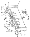
- the roof 29 retractable in the trunk 1 of a vehicle discoverable 30, comprises a front roof element 2 and a rear roof element 3, connected to the bodywork 31 of the vehicle 30 by means making it possible to move the two elements 2, 3 above between a position in which (see Figure 1) these two elements 2, 3 cover the passenger compartment 26 of the vehicle 30 and a position (see Figures 2 and 3) in which they are stored in the trunk 1.
- the means above comprise, on the one hand, two arms 4, 5 connected in a manner pivoting to the bodywork 31 by joints 6, 7 and to the front roof element 2 by others joints 8, 9 so as to constitute a quadrilateral, if necessary a parallelogram, deformable and, on the other hand, two slides 10, 11 secured to the bodywork 31.
- the upper end of the slides 10, 11 is located near the lower edge 3a of the roof element back 3 and the lower end of the slides is located inside the trunk 1.
- the slides 10, 11 are shaped to guide the movement of the rear roof element 3 between a position in which (see Figure 1) this element 3 covers the rear part of the passenger compartment of vehicle and a position in which (see Figure 2) this element 3 is entirely housed in the trunk back 1.
- the two arms 4, 5 hinged to the front roof element 2 can pivot between a position (see Figure 1) in which this element 2 covers the front part of the cockpit and a position (see Figure 2) in which this element 2 is fully housed in the trunk 1 in a substantially parallel position to the roof element back 3.
- the upper ends of the slides 10, 11 are located respectively near the front of the edge lower 3a of the rear roof element 3 and near the back of this edge 3a.
- the slide 10 whose end upper is located near the front of the lower edge 3a of the rear roof element has a shape substantially in an arc whose convexity is directed towards back and up the chest 1.
- the other slide 11 has substantially the shape a very flattened S extending backward and downward of the chest 1.
- the cable 14 is looped around the three guides 15, 16, 17 which are located respectively near the ends opposite of the slide 10 and near the middle thereof.
- the cable 14 is in in addition wound several turns on a cylinder 18 whose rotation is controlled by an electric motor 19.
- cable 14 is fixed on the cylinder 18 at a point 20.
- the rear roof element 3 is driven along the slides 10, 11 by means of a jack 21 whose rod 22 is hingedly attached at a point 24 on the edge lower 3a of the rear roof element 3.
- the body 23 of the jack 21 is fixed so articulated at a point 25 of the body.
- Figure 6 shows the two extreme positions of the cylinder 21 and the rear roof element 3.
- the retractable roof 29 can include means to successively order the training of the rear roof element 3 to its position of storage in the trunk, then the training of the front roof element 2 to a position of storage in the trunk where this element 2 is arranged above the rear roof element 3, as shown in Figure 2.
- the retractable roof 29 includes means for successively order the training of the element of rear roof 3 to an intermediate position 3 ' (see Figures 1 and 3) in which this element clears access to the trunk 1 for the front roof element 2, then the drive of this front roof element 2 towards the storage position in the trunk 1 and then the final movement of the rear roof element 3 towards a storage position in the trunk where this element 3 is disposed above the front roof element 2, as shown in Figure 3.
- the control of the pivoting of the arms 4, 5 to the trunk 1 can be realized, at means of an electric motor whose output shaft is connected to one of the joints 6, 7.
- the trunk 1 has a maximum width L1, in the trunk part 32 located above the wheels 33, slightly larger than the maximum width L2 of the rear roof element 3.
- such a vehicle 30 has rear fenders 34 giving the rear of the vehicle a total width greater than the width L2 of the base of the roof, which corresponds to the style close to a coupe.
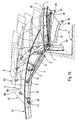
- Figures 9 and 10 the slides before 37 and rear 38 each have a respective shaped profile, and the rollers 39, 40 are attached to the lower side edge 3a of the rear roof 3, so as to obtain this sliding of the rear roof element 3 under the wings 34.
- the slide rear 38 has an angled profile including in the direction 36 from the front to the back a first section 41 substantially rectilinear with a first steep slope backward and downward followed by a second substantially straight section 42 having a second slope lower than the first slope.
- the higher slope of the first section 41 allows to dive quickly the rear edge 43 of the rear roof element 3 to the interior of the part 32 of the trunk 1, while the lower slope of the second section 42 guides said edge rear 43 substantially according to the slope of the lid 35 from the trunk.
- the front slide 37 has a substantially S-shaped profile comprising a central section 44 substantially rectilinear having an intermediate slope between the first slope and the second slope of the rear slide 38.
- the central section 44 is preceded forward and upward by an upper section 45 short and is followed down and back by a lower section 46 runs both stronger slopes.
- the pebbles front 47 and rear 48 are attached to gussets respective front 49 and rear 50 extending down from the lower side edge 3a of the element of rear roof 3.
- the respective upper ends 37a, 38a slides 37, 38 are located below the surface upper substantially horizontal 51 wings rear 34 corresponding vehicle, this surface 51 substantially delimiting a separation plan between the actual bodywork and the roof element back 3.
- the roof element back 3 can be operated for example by a cable system of the type described above.
- Figures 10 and 11 one of the slides, 59, has a cross section substantially C with a rack 52.
- the corresponding roller 53 is a pinion meshing with the rack 52 and driven by a shaft 54 secured to a second pinion 55 actuated by a electric motor 56 via a pinion engine 57.
- the electric motor 56 is fixed in the rear quarter corresponding 58 which is part of the roof element rear 3, as shown schematically in Figures 10 and 11.
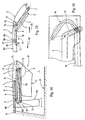
- the retractable roof 61 comprises, in before the front roof element 2, a third element mobile roof 62, and means for moving said third roof element 62 in one direction or in the other between a closed position, schematized at the Figure 12, in which it covers the passenger compartment 26 between the front roof element 2 and the cross member 63 of the windscreen 64, and an open position, shown schematically in FIG. Figure 14, in which it is stored in the trunk rear 1 with front roof elements 2 and rear 3.
- the third roof element 62 is articulated on the front roof element 2, by example, on each side of the vehicle, by a point 65 hinge located near the rear edge 66 of said third element 62 and carried by a finger 67 projecting forward, in the direction of arrow 68, relative to the front edge 69 of the front roof element 2.
- the third roof element 62 is furthermore connected to the front roof element 2 by a lever 70 articulated at its front end to a point front articulation 71 located in front of the point main articulation 65, and at its rear end at a rear hinge point 72 carried by example, by an extension 73 up the arm back 4 so that the third element of roof 62 is in its open position, schematically in Figures 12, 14 and 15, in a position substantially vertical in front of the front roof elements 2 and back 3.
- the vertical position of the third element 62 inside the trunk 1 allows, with the aforementioned provision of the front roof elements 2 and rear 3 in a substantially horizontal position, book inside the trunk 1 a space reserved for luggage of satisfactory volume.
- the extension 73 of the rear arm 4 has, in the mode of embodiment of Figure 16, an oblong opening 76 crossed by an axis 77 constituting the point rear articulation 72 of the lever 70.
- the axis 77 slides on the one hand along the oblong opening 76 and secondly along a second angled opening 78 formed in a fixed wall secured to the front roof element 2 and acting cam to guide the angular movement of the third roof element 62.
- the retractable roof 61 includes means for locking roof elements 2, 3, 62 constituted and / or actuated by rotary rods successive stages comprising means for transmitting rotational movement of one rod 82, 84 to another 84, 88 and a roof element 3, 2 to the other 2, 62, by example of the type described in WO-A-054 997. This document is not taken into consideration for the assessment of the inventive step.
- an engine electrical 81 housed in each pantry 58 drives a first rotary rod 82 whose upper end leads to a first coupling means 83 ensuring both the transmission of the rotational movement to the second rotary rod 84 carried by the roof element before 2, and locking the front edge 85 of the rear roof element 3 with the trailing edge 86 of the front roof element 2.
- the second rod 84 leads to a second coupling means 87 ensuring both the transmission of the rotation movement to the third rod 88 carried by the third roof element 62, and locking the front edge 89 of the roof element before 2 with the rear edge 90 of the third element of roof 62.
- the front end of the third rod 88 is terminated by a locking means 91 ensuring the locking the front edge 92 of the third element of roof 62 with additional locking means 93 of the cross member 63 of the windshield 64.
- the locking means 83, 87, 91, 93 are for example described in WO-A-054,997.
- the first stem rotary device 82 has, as shown diagrammatically in FIG. a first conical gear 94 meshing with a second conical pinion 95 integral with a spur gear 96 which meshes with two racks 97, 98 located either side of the spur gear 96 and driven by this last in different senses.
- Each rack 97, 98 comprises at its end a conical finger 97a, 98a, adapted to engage in a respective housing 99, 100 of the bodywork 31 of the vehicle 30 to lock the base of the element of rear roof 3 on said bodywork 31.
- the locking means may comprise also sliding fingers in the direction Transverse of the vehicle powered by the rotating rod corresponding 82, 84, 88 via a respective pinion and rack (no shown).
- the rollbar must obligatorily be a rollbar retractable adapted to be in a low position in the closed position of the retractable roof so as not to rearward movement of the rear roof element 3 sliding under the lid 35 of the chest 1 and under them rear fenders 34 of the vehicle.
- This retractable arch can be of a type any, and can be for example a hoop retractable of the type described in (WO-A-055 015) schematized in Figure 19. This document is not taken into consideration for the assessment of the inventive step.
- the retractable arch 101 is consisting of two individual hoops 102 arranged each in the backrest 103 of the corresponding rear seat.
- Each individual arch 102 consists of two hoop elements 104 hinged to each other in 105 at the top of the arch 102.
- the lower extremities 106 of the two elements of arches 104 of the same individual arch 102 can be move in different directions in the direction cross-section of the vehicle between a first position retracted, in which the two ends 106 are distant from each other and the 105 joint is close to the upper surface 107 of the folder 103, and a second output position in which the two ends 106 are brought closer to each other and the hinge 105 is at a maximum distance above the surface 107.
- This movement is for example controlled by the rotation of a threaded rod with parts opposed threaded threads for both ends 106 of elements 104 of the same arch 102.
- the displacement of said arch 101 of one of its positions to the other is controlled, in the mode of embodiment of Figure 19, by moving corresponding to the front roof element 2, for example through a pinion 108 mounted on the axis of rotation 109 of one of the arms 4, 5, the front arm 4 to said figure 19.
- the front roof element 2 When the rear roof element 3 is in its stowed position inside the trunk 1, the front roof element 2 can be opened, as schematized by the arrow 111 in the same figure 9, by actuation of the arms 4 and 5, and the retractable arch 101 can be pulled out at the same time high, as shown schematically by the arrow 112 in this figure 9.
Landscapes
- Engineering & Computer Science (AREA)
- Mechanical Engineering (AREA)
- Body Structure For Vehicles (AREA)
Description
- la figure 1 est une vue schématique en élévation d'un toit rétractable selon l'invention ;
- la figure 2 montre le toit replié à l'intérieur du coffre,
- la figure 3 illustre une autre version du repliage du toit à l'intérieur du coffre ;
- la figure 4 est une vue schématique de l'élément arrière du toit, des glissières , du câble et du moteur d'entraínement de ce dernier ;
- la figure 5 est une vue suivant F de la figure 4 ;
- la figure 6 montre un vérin pour commander le déplacement de l'élément arrière du toit ;
- la figure 7 est une vue schématique en élévation, avec arrachement, de l'arrière d'un véhicule comportant une variante de toit découvrable dont les éléments sont repliés dans le coffre;
- la figure 8 est une vue très agrandie d'un détail de la figure 7 ;
- la figure 9 est une vue semblable à la figure 1 du mode de réalisation schématisé figures 7 et 8 ;
- la figure 10 est une vue très agrandie illustrant les glissières de la figure 9 ;
- la figure 11 est une vue partielle agrandie en coupe selon XI-XI à la figure 10 ;
- la figure 12 est une vue schématique semblable à la figure 1 d'un autre mode de réalisation de l'invention ;
- la figure 13 est une vue agrandie d'un détail de la figure 12 illustrant les moyens de liaison entre l'élément de toit avant et le troisième élément de toit ;
- la figure 14 est une vue semblable à la figure 13 représentant les éléments de toit repliés dans le coffre ;
- la figure 15 montre différentes positions prises par les trois éléments du toit entre les positions représentées respectivement aux figures 13 et 14 ;
- la figure 16 est une vue agrandie du détail A de la figure 14 selon une variante ;
- la figure 17 est une vue semblable à la figure 13 illustrant les moyens de verrouillage des éléments de toit dans leur position fermée ;
- la figure 18 est une vue agrandie de dessus d'un détail de la figure 17 ;
- la figure 19 est une vue en perspective illustrant une réalisation d'arceau escamotable utilisable avec le mode de réalisation des figures 7 à 16.
Claims (15)
- Toit (29, 61) rétractable dans le coffre arrière (1) d'un véhicule découvrable (30), comprenant au moins un élément de toit avant (2) et un élément de toit arrière (3), reliés à la carrosserie (31) du véhicule (30) par des moyens permettant de déplacer les deux éléments (2, 3) ci-dessus entre une position dans laquelle ces deux éléments (2, 3) recouvrent l'habitacle (26) du véhicule (30) et une position dans laquelle ceux-ci sont rangés dans le coffre arrière (1), caractérisé en ce que les moyens ci-dessus comprennent, d'une part, deux bras (4, 5) reliés de façon pivotante à la carrosserie (31) par des articulations (6, 7) et à l'élément de toit avant (2) par d'autres articulations (8, 9) de façon à constituer un quadrilatère déformable et, d'autre part, deux glissières (10, 11; 37, 38; 59) solidaires de la carrosserie dans chacune desquelles est engagé un galet (12, 13; 39, 40; 53) porté par le bord inférieur (3a) de l'élément de toit arrière (3), l'extrémité supérieure des glissières (10, 11; 37, 38; 59) étant située près du bord inférieur (3a) de l'élément de toit arrière (3) et l'extrémité inférieure des glissières (10, 11; 37, 38; 59) étant située à l'intérieur du coffre arrière (1), les glissières (10, 11; 37, 38; 59) étant conformées pour guider le déplacement de l'élément de toit arrière (3) entre une position dans laquelle cet élément (3) recouvre la partie arrière de l'habitacle (26) du véhicule (30) et une position dans laquelle cet élément (3) est entièrement logé dans le coffre arrière (1), les deux bras (4, 5) articulés à l'élément de toit avant (2) pouvant pivoter entre une position dans laquelle cet élément (2) recouvre la partie avant de l'habitacle (26) et une position dans laquelle cet élément (2) est entièrement logé dans le coffre arrière (1) dans une position sensiblement parallèle à l'élément de toit arrière (3), et en ce que, de préférence, les extrémités supérieures des glissières (10, 11) sont situées respectivement près de l'avant du bord inférieur (3a) de l'élément de toit arrière (3) et près de l'arrière de ce bord (3a).
- Toit rétractable (29) conforme à la revendication 1, caractérisé en ce que la glissière (10) dont l'extrémité supérieure est située près de l'avant du bord inférieur (3a) de l'élément de toit arrière (3) a une forme sensiblement en arc de cercle dont la convexité est dirigée vers l'arrière et vers le haut du coffre, l'autre glissière (11) ayant sensiblement la forme d'un S très aplati s'étendant vers l'arrière et le bas du coffre.
- Toit rétractable (29) conforme à l'une des revendications 1 ou 2, caractérisé en ce que l'élément de toit arrière (3) est entraíné le long des glissières (10, 11) au moyen d'un câble (14) solidaire de l'un (12) des galets (12, 13) dont le déplacement suivant la glissière (10) correspondante est guidé au moyen de guides (15, 16, 17), le câble (14) étant avantageusement enroulé en boucle autour de trois guides (15, 16, 17) disposés respectivement près des extrémités de la glissière (10) et près du milieu de celle-ci, le câble (14) étant de préférence en outre enroulé plusieurs tours sur un cylindre (18) dont la rotation est commandée par un moteur électrique (19), ou au moyen d'un vérin (21) dont la tige (22) est fixée de façon articulée au bord inférieur (3a) de l'élément de toit arrière (3) et dont le corps (23) est fixé de façon articulée à la carrosserie.
- Toit rétractable (29) conforme à l'une des revendications 1 à 3, caractérisé en ce qu'il comprend des moyens pour commander successivement l'entraínement de l'élément de toit arrière (3) jusqu'à sa position de rangement dans le coffre (1), puis l'entraínement de l'élément de toit avant (2) jusqu'à une position de rangement dans le coffre où cet élément (2) est disposé au-dessus de l'élément de toit arrière (3), ou bien des moyens pour commander successivement l'entraínement de l'élément de toit arrière (3) jusqu'à une position intermédiaire (3') dans laquelle cet élément dégage l'accès au coffre (1) pour l'élément de toit avant (2), puis l'entraínement de cet élément de toit avant (2) vers la position de rangement dans le coffre et ensuite le déplacement final de l'élément de toit arrière (3) vers une position de rangement dans le coffre (1) où cet élément (3) est disposé au-dessus de l'élément de toit avant (2).
- Toit rétractable (61) selon la revendication 1, le coffre arrière (1) ayant une largeur maximale (L1) plus grande que la largeur maximale (L2) de l'élément de toit arrière (3), caractérisé en ce que les glissières (37, 38) ont chacune un profil respectif conformé de manière telle, et les galets (39, 40) sont fixés sur le bord latéral inférieur (3a) de l'élément arrière (3) de façon telle que ledit élément de toit arrière (3) lors de son déplacement dans le sens (36) vers l'arrière du véhicule est guidé de façon à glisser vers le bas et à se loger sous les ailes arrière (34) du véhicule (30).
- Toit rétractable (61) selon la revendication 5, caractérisé en ce que la glissière arrière (38) a un profil coudé comprenant de l'avant vers l'arrière un premier tronçon(41) sensiblement rectiligne ayant une première pente dirigée vers l'arrière et vers le bas, suivi par un second tronçon (42) sensiblement rectiligne ayant une seconde pente inférieure à la première pente.
- Toit rétractable (61) selon la revendication 5 ou 6, caractérisé en ce que la glissière avant (37) a un profil sensiblement en S comprenant un tronçon central (44) sensiblement rectiligne ayant une pente intermédiaire entre la première pente et la seconde pente de la glissière arrière (38), précédé par un tronçon supérieur(45) court et suivi par un tronçon inférieur (46) court de plus fortes pentes
- Toit rétractable (61) selon l'une quelconque des revendications 5 à 7, caractérisé en ce que les galets (47, 48) sont fixés sur des goussets respectifs (49, 50) s'étendant vers le bas à partir du bord latéral inférieur (3a) de l'élément de toit arrière (3) de sorte que les extrémités supérieures respectives (37a, 38a) des glissières (37, 38) sont situées sous la surface sensiblement horizontale (51) de l'aile arrière (34) correspondante du véhicule (30).
- Toit rétractable (61) selon l'une quelconque des revendications 1 et 5 à 9, caractérisé en ce que l'une (59) des glissières a en coupe transversale une forme sensiblement en C comportant une crémaillère (52), en ce que le galet (53) correspondant est un pignon engrenant avec la crémaillère (52) et entraíné par un arbre (54) solidaire d'un second pignon (55) actionné par un moteur électrique (56) porté par l'élément de toit arrière (3).
- Toit rétractable (61) selon l'une quelconque des revendications précédentes, caractérisé en ce qu'il comporte en avant de l'élément de toit avant (2) un troisième élément de toit (62) mobile et des moyens pour déplacer ledit troisième élément de toit (62) dans un sens ou dans l'autre entre une position fermée, dans laquelle il recouvre l'habitacle (26) entre l'élément de toit avant (2) et la traverse (63) du pare-brise (64), et une position ouverte dans laquelle il est rangé dans le coffre arrière (1) avec les éléments de toit avant (2) et arrière (3).
- Toit rétractable (61) selon la revendication 10, caractérisé en ce que le troisième élément de toit (62) est monté articulé sur l'élément de toit avant (2), par exemple de chaque côté par un point d'articulation principal (65) situé près du bord arrière (66) dudit troisième élément (62) et porté par un doigt (67) en saillie vers l'avant par rapport au bord avant (69) de l'élément de toit avant (2).
- Toit rétractable (61) selon la revendication 11, caractérisé en ce que le troisième élément de toit (62) est en outre relié à l'élément de toit avant (2) par un levier (70) articulé à son extrémité avant en un point d'articulation avant (71) situé en avant du point d'articulation principal (65), et à son extrémité arrière en un point d'articulation arrière (72) porté par exemple par un prolongement (73) vers le haut du bras arrière (4) de manière telle que le troisième élément de toit (62) se retrouve dans sa position ouverte dans une position sensiblement verticale devant les éléments de toit avant (2) et arrière (3).
- Toit rétractable (61) selon la revendication 12, caractérisé en ce que le prolongement (73) du bras arrière (4) comporte à son extrémité une ouverture oblongue (76) traversée par un axe (77) constituant le point d'articulation arrière (72) du levier (70), et en ce que ledit axe (77) coulisse d'une part le long de ladite ouverture oblongue (76) et d'autre part le long d'une seconde ouverture coudée (78) faisant office de came pour guider le mouvement angulaire du troisième élément de toit (62).
- Toit rétractable (61) selon l'une quelconque des revendications précédentes, caractérisé en ce qu'il comporte des moyens de verrouillage des éléments de toit (2, 3, 61) au moins dans leur position fermée, ces moyens de verrouillage (83, 87, 91, 93) étant constitués et/ou actionnés par des tiges rotatives (82, 84, 88) successives comprenant des moyens de transmission du mouvement de rotation d'une tige (82, 84) à l'autre (84, 88) et d'un élément de toit (3, 2) à l'autre (2, 61), ces tiges (82, 84, 88) étant le cas échéant associées à des crémaillères (97, 98) actionnant des doigts de verrouillage coulissants (97a, 98a).
- Toit rétractable (29, 61) selon l'une quelconque des revendications précédentes, ce toit (29, 61) étant associé à un arceau escamotable (101) adapté à être en position haute ou basse respectivement lorsque le toit rétractable (29, 61) est dans sa position ouverte ou fermée, caractérisé en ce que le déplacement dudit arceau (101) de l'une de ses positions à l'autre est commandé par le déplacement correspondant de l'élément de toit avant (2), par exemple par l'intermédiaire d'un pignon (108) monté sur l'axe de rotation (109) de l'un des bras (4, 5).
Applications Claiming Priority (5)
| Application Number | Priority Date | Filing Date | Title |
|---|---|---|---|
| FR9906655A FR2794073B1 (fr) | 1999-05-26 | 1999-05-26 | Toit retractable dans le coffre d'un vehicule decouvrable |
| FR9906655 | 1999-05-26 | ||
| FR9916174A FR2794074B1 (fr) | 1999-05-26 | 1999-12-21 | Toit retractable dans le coffre arriere d'un vehicule decouvrable |
| FR9916174 | 1999-12-21 | ||
| PCT/FR2000/001406 WO2000073096A1 (fr) | 1999-05-26 | 2000-05-23 | Toit retractable dans le coffre arriere d'un vehicule decouvrable |
Publications (2)
| Publication Number | Publication Date |
|---|---|
| EP1180076A1 EP1180076A1 (fr) | 2002-02-20 |
| EP1180076B1 true EP1180076B1 (fr) | 2005-05-18 |
Family
ID=26234971
Family Applications (1)
| Application Number | Title | Priority Date | Filing Date |
|---|---|---|---|
| EP00935252A Expired - Lifetime EP1180076B1 (fr) | 1999-05-26 | 2000-05-23 | Toit retractable dans le coffre arriere d'un vehicule decouvrable |
Country Status (5)
| Country | Link |
|---|---|
| EP (1) | EP1180076B1 (fr) |
| DE (1) | DE60020227T2 (fr) |
| ES (1) | ES2240104T3 (fr) |
| FR (1) | FR2794074B1 (fr) |
| WO (1) | WO2000073096A1 (fr) |
Families Citing this family (1)
| Publication number | Priority date | Publication date | Assignee | Title |
|---|---|---|---|---|
| DE10329439A1 (de) * | 2003-07-01 | 2005-01-27 | Daimlerchrysler Ag | Cabriolet-Fahrzeug mit einem Hardtop |
Family Cites Families (4)
| Publication number | Priority date | Publication date | Assignee | Title |
|---|---|---|---|---|
| EP0101322A3 (fr) * | 1982-08-17 | 1984-04-18 | Mga Developments Limited | Véhicule à système de toit coulissant |
| DE3635887A1 (de) * | 1986-10-22 | 1988-05-05 | Ernst Dipl Ing Maier | Schwenkbares fahrzeugdach |
| US5078447A (en) * | 1990-01-12 | 1992-01-07 | C&C Incorporated | Multi-position retractable vehicle roof |
| DE4445580C1 (de) * | 1994-12-20 | 1995-12-21 | Daimler Benz Ag | Hardtop-Fahrzeug |
-
1999
- 1999-12-21 FR FR9916174A patent/FR2794074B1/fr not_active Expired - Fee Related
-
2000
- 2000-05-23 ES ES00935252T patent/ES2240104T3/es not_active Expired - Lifetime
- 2000-05-23 DE DE60020227T patent/DE60020227T2/de not_active Expired - Lifetime
- 2000-05-23 WO PCT/FR2000/001406 patent/WO2000073096A1/fr not_active Ceased
- 2000-05-23 EP EP00935252A patent/EP1180076B1/fr not_active Expired - Lifetime
Also Published As
| Publication number | Publication date |
|---|---|
| DE60020227D1 (de) | 2005-06-23 |
| FR2794074A1 (fr) | 2000-12-01 |
| WO2000073096A1 (fr) | 2000-12-07 |
| EP1180076A1 (fr) | 2002-02-20 |
| ES2240104T3 (es) | 2005-10-16 |
| FR2794074B1 (fr) | 2002-04-12 |
| DE60020227T2 (de) | 2005-10-13 |
Similar Documents
| Publication | Publication Date | Title |
|---|---|---|
| EP1240042B1 (fr) | Toit escamotable dans le coffre arriere d'un vehicule | |
| FR2759729A1 (fr) | Dispositif pour commander l'ouverture et la fermeture de la malle arriere et de la plage arriere d'un vehicule decouvrable | |
| EP1123220B1 (fr) | Module de recouvrement amovible d'un habitacle de vehicule automobile et un vehicule automobile equipe d'un tel module | |
| EP1282536B1 (fr) | Systeme de toit rigide escamotable pour vehicule decouvrable | |
| EP1369276A1 (fr) | Dispositif formant volet de coffre arrière d'un véhicule automobile | |
| EP1272369B1 (fr) | Systeme de toit ouvrant pour vehicule decrouvrable | |
| EP1320467B1 (fr) | Toit escamotable pour vehicule et vehicule notamment du type pick-up equipe d'un tel toit | |
| FR2857625A1 (fr) | Vehicule a toit ouvrant escamotable et procede de rangement d'un tel toit, avec un systeme de basculement horizontal | |
| EP1328416B1 (fr) | Toit retractable pour vehicule, comprenant trois elements longitudinaux | |
| EP1478535A1 (fr) | Toit escamotable basculant pour vehicule automobile | |
| EP1180076B1 (fr) | Toit retractable dans le coffre arriere d'un vehicule decouvrable | |
| EP1633585B1 (fr) | Vehicule a toit ouvrant repliable verticalement | |
| EP1426235A1 (fr) | Véhicule automobile transformable en véhicule à benne ouverte vers le haut | |
| FR2806969A1 (fr) | Vehicule automobile a lunette escamotable | |
| EP1151880B1 (fr) | Porte transformable de véhicule automobile | |
| FR2896188A1 (fr) | Toit escamotable dans un coffre | |
| FR2828838A1 (fr) | Vehicule automobile de type berline transformable en un vehicule automobile a benne ouverte vers le haut | |
| FR2815581A1 (fr) | Toit retractable pour vehicule, comprenant deux elements longitudinaux | |
| FR2854353A1 (fr) | Element arriere de toit escamotable et vehicule ainsi equipe | |
| EP1564053A1 (fr) | Toit rigide escamotable pour véhicule automobile | |
| EP1648725A2 (fr) | Element arriere de toit escamotable et vehicule ainsi equipe | |
| FR2897558A1 (fr) | Toit escamotable dans un coffre de vehicule avec glissieres | |
| FR2744979A1 (fr) | Dispositif de basculement d'une lunette arriere pour vehicule automobile | |
| FR2845950A1 (fr) | Toit escamotable pour vehicule | |
| FR2851748A1 (fr) | Toit escamotable de vehicule |
Legal Events
| Date | Code | Title | Description |
|---|---|---|---|
| PUAI | Public reference made under article 153(3) epc to a published international application that has entered the european phase |
Free format text: ORIGINAL CODE: 0009012 |
|
| 17P | Request for examination filed |
Effective date: 20011027 |
|
| AK | Designated contracting states |
Kind code of ref document: A1 Designated state(s): AT BE CH CY DE DK ES FI FR GB GR IE IT LI LU MC NL PT SE |
|
| 111L | Licence recorded |
Free format text: 20020220 0100 FRANCE DESIGN |
|
| RAP1 | Party data changed (applicant data changed or rights of an application transferred) |
Owner name: SOCIETE EUROPEENNE DE BREVETS AUTOMOBILES |
|
| RBV | Designated contracting states (corrected) |
Designated state(s): DE ES GB |
|
| GRAP | Despatch of communication of intention to grant a patent |
Free format text: ORIGINAL CODE: EPIDOSNIGR1 |
|
| RTI1 | Title (correction) |
Free format text: RETRACTABLE ROOF IN THE REAR BOOT OF A COVERABLE VEHICLE |
|
| GRAS | Grant fee paid |
Free format text: ORIGINAL CODE: EPIDOSNIGR3 |
|
| GRAA | (expected) grant |
Free format text: ORIGINAL CODE: 0009210 |
|
| AK | Designated contracting states |
Kind code of ref document: B1 Designated state(s): DE ES GB |
|
| REG | Reference to a national code |
Ref country code: GB Ref legal event code: FG4D Free format text: NOT ENGLISH |
|
| GBT | Gb: translation of ep patent filed (gb section 77(6)(a)/1977) |
Effective date: 20050518 |
|
| REG | Reference to a national code |
Ref country code: IE Ref legal event code: FG4D Free format text: LANGUAGE OF EP DOCUMENT: FRENCH |
|
| REF | Corresponds to: |
Ref document number: 60020227 Country of ref document: DE Date of ref document: 20050623 Kind code of ref document: P |
|
| REG | Reference to a national code |
Ref country code: ES Ref legal event code: FG2A Ref document number: 2240104 Country of ref document: ES Kind code of ref document: T3 |
|
| PLBE | No opposition filed within time limit |
Free format text: ORIGINAL CODE: 0009261 |
|
| STAA | Information on the status of an ep patent application or granted ep patent |
Free format text: STATUS: NO OPPOSITION FILED WITHIN TIME LIMIT |
|
| 26N | No opposition filed |
Effective date: 20060221 |
|
| PGFP | Annual fee paid to national office [announced via postgrant information from national office to epo] |
Ref country code: ES Payment date: 20100611 Year of fee payment: 11 |
|
| REG | Reference to a national code |
Ref country code: ES Ref legal event code: FD2A Effective date: 20121122 |
|
| PG25 | Lapsed in a contracting state [announced via postgrant information from national office to epo] |
Ref country code: ES Free format text: LAPSE BECAUSE OF NON-PAYMENT OF DUE FEES Effective date: 20110524 |
|
| PGFP | Annual fee paid to national office [announced via postgrant information from national office to epo] |
Ref country code: DE Payment date: 20150519 Year of fee payment: 16 Ref country code: GB Payment date: 20150520 Year of fee payment: 16 |
|
| REG | Reference to a national code |
Ref country code: DE Ref legal event code: R119 Ref document number: 60020227 Country of ref document: DE |
|
| GBPC | Gb: european patent ceased through non-payment of renewal fee |
Effective date: 20160523 |
|
| PG25 | Lapsed in a contracting state [announced via postgrant information from national office to epo] |
Ref country code: DE Free format text: LAPSE BECAUSE OF NON-PAYMENT OF DUE FEES Effective date: 20161201 |
|
| PG25 | Lapsed in a contracting state [announced via postgrant information from national office to epo] |
Ref country code: GB Free format text: LAPSE BECAUSE OF NON-PAYMENT OF DUE FEES Effective date: 20160523 |