EP1180416A2 - Outil électroportatif à dispositif de serrage rapide - Google Patents
Outil électroportatif à dispositif de serrage rapide Download PDFInfo
- Publication number
- EP1180416A2 EP1180416A2 EP01119414A EP01119414A EP1180416A2 EP 1180416 A2 EP1180416 A2 EP 1180416A2 EP 01119414 A EP01119414 A EP 01119414A EP 01119414 A EP01119414 A EP 01119414A EP 1180416 A2 EP1180416 A2 EP 1180416A2
- Authority
- EP
- European Patent Office
- Prior art keywords
- cam
- actuating element
- clamping
- power tool
- eccentric
- Prior art date
- Legal status (The legal status is an assumption and is not a legal conclusion. Google has not performed a legal analysis and makes no representation as to the accuracy of the status listed.)
- Granted
Links
Images


Classifications
-
- B—PERFORMING OPERATIONS; TRANSPORTING
- B24—GRINDING; POLISHING
- B24B—MACHINES, DEVICES, OR PROCESSES FOR GRINDING OR POLISHING; DRESSING OR CONDITIONING OF ABRADING SURFACES; FEEDING OF GRINDING, POLISHING, OR LAPPING AGENTS
- B24B45/00—Means for securing grinding wheels on rotary arbors
- B24B45/006—Quick mount and release means for disc-like wheels, e.g. on power tools
-
- B—PERFORMING OPERATIONS; TRANSPORTING
- B24—GRINDING; POLISHING
- B24B—MACHINES, DEVICES, OR PROCESSES FOR GRINDING OR POLISHING; DRESSING OR CONDITIONING OF ABRADING SURFACES; FEEDING OF GRINDING, POLISHING, OR LAPPING AGENTS
- B24B23/00—Portable grinding machines, e.g. hand-guided; Accessories therefor
- B24B23/02—Portable grinding machines, e.g. hand-guided; Accessories therefor with rotating grinding tools; Accessories therefor
Definitions
- the invention relates to a power tool, in particular a Angle grinder, which is a quick release device for attachment of a tool on a spindle with a Clamping flange and a counter flange, between which the tool non-rotatable under the action of an elastic pressing means is clamped, an actuator that between a Clamping position and a release position is movable, in which Release position the tension between the counter flange and the Clamping flange against the action of the elastic pressure medium is lifted, and a cam acting on the clamping flange, the at least in the release position by a motor of the Power tool is rotatable and at least at the when transferring the actuator from the clamping position in the release position a trained on the actuator Tread engages, causing movement of the actuator can be implemented in an axial displacement of the clamping flange is and the actuating element in the release position with the engine stopped taking advantage of one between the cam and the friction force acting on the tread.
- a power tool in particular a Angle grinder,
- Such a power tool is known from EP 0 152 564 A2.
- This known power tool has a quick release device with which disc-shaped tools, e.g. Grinding discs or circular saw blades, quickly and easily replaced can be.
- the quick release includes this purpose a clamping flange designed as a nut and a counter flange, between which the disc-shaped tool is tensioned.
- the clamping flange is on a clamping bolt screwed on in one of the power tool's motor driven hollow spindle non-rotatably, but in the axial direction is arranged movably.
- the clamping bolt is opposite the Hollow spindle so clamped by means of a spring that due to the spring action of the clamping flange screwed onto the clamping bolt is pulled towards the counter flange.
- an actuating element designed as a rotary lever By transferring an actuating element designed as a rotary lever from a clamping to a release position Remove tension between the clamping flange and the counter flange.
- a cylindrical socket is formed on the rotary lever, which is screwed into the housing of the power tool is.
- the nozzle is further in screwed the housing in until it finally touched the socket facing end of the clamping bolt and this, together with the clamping flange screwed onto it. So that the tension between the clamping flange and the counter flange, so that the clamping flange can now be unscrewed by hand from the clamping bolt. Subsequently the tool can be exchanged for another tool.
- the pivot lever is over a shift rod with a switch to turn on the engine connected in such a way that the motor can only be switched on can when the actuating element is in the clamping position.
- This measure prevents if the actuating element is in the release position, the lowered print head with its underside from above on the Pressure piece that presses with high after turning on the engine Speed would rotate. Without such a measure would be due to the comparatively high forces to weld or deformation between the printhead and the Pressure piece (or a friction plate attached to it).
- the mechanical connection between the actuator and the switch for switching on the motor is constructive comparatively complex.
- this task solved in that the cam and the tread on each other are coordinated that in the release position by Turning the motor on caused the cam to rotate Frictional force between the cam and the tread is reduced so that in the release position of the elastic pressure means acted on cam the actuator from the Release position moved to the clamping position.
- a flange and a counter flange are used here every component understood that a tool is suitable to clamp a shaft.
- the clamping flange can especially a conventional nut that is screwed onto the shaft.
- tension and release position are not in the present case to understand the restrictive sense that this is an exact defined position should be designated. Under the clamping position is rather every position, also a larger position range, to understand the actuator, in which a at least partially bracing the clamping flange and counter flange is achieved. Are corresponding with the release position designated all positions where there is no tension exists between the clamping flange and the counter flange. If thus from a movement of the actuating element from the release Tensioned position is spoken, this ultimately means that the actuator is moved until the Tension has occurred at least partially. The reverse is true to relieve the components of the quick release device, so practical additional forces generated by the engine can no longer cause damage.
- the tread at least has two sections of different slope.
- the Slope of the tread in the release position of the actuating element is smaller than the slope of the tread in the tensioned position.
- the tread is the rolling surface of the actuator trained eccentric rotatably mounted about an axis of rotation.
- the actuator one attached to the eccentric shaft Swivel lever that is about the axis of rotation of the eccentric is pivotable.
- pivot lever has the advantage that so that much greater torques can be applied than this is the case with a rotary knob.
- the attachment of the swivel lever on Eccentric can also be done via a freewheel. If that Actuator is in the release position, moves only the eccentric when starting the motor, not the one Swivel lever back to the clamping position.
- the eccentricity of the eccentric is between 1% and 20% of the largest diameter of the eccentric.
- the surfaces of the cam and the tread have a Vickers hardness of more than 54, preferably about 64, and a roughness depth R z between 0.2 ⁇ m and 8 ⁇ m.
- the surfaces of the cam and the tread from one porous sintered material whose pores near the surface are covered with a Lubricants are filled up.
- the cam can be part of the pressure piece or firmly with it be connected so that every movement of the actuator directly on the pressure piece and thus on it attached clamping flange transmits. But then it's for it To ensure that at least in the clamping position between the tread and the cam remain a short distance, so that it does not become a when operating the power tool permanent friction between the rotating cam and the Tread of the actuator comes.
- the Cams are not directly connected to the pressure piece. Rather, the cam is part of a printhead that is in a Sleeve is rotatably mounted and when the actuating element is transferred in the release position against the effect of a elastic pressing means that the cam of the print head presses the tread of the actuating element, axially so in Direction of the pressure piece is shifted so that the print head at least indirectly comes into frictional engagement with the pressure piece.
- a first embodiment for a power tool according to the invention in the form of an angle grinder is in total in Fig. 1 designated 10.
- the motor / transmission unit 14 has an electric motor 16, whose motor shaft 18 is a pinion 20 for a bevel gear wearing.
- An output gear 22 of the bevel gear is rotationally fixed connected to a hollow spindle 24 which is not shown in FIG. 1 shown - ball bearings rotatably mounted about an axis of rotation 25 is.
- a counter flange 26 is formed at the end of the hollow spindle 24, a clamping flange 28 for clamping a tool 30 assigned.
- Tool 30 is shown in FIG Embodiment around a grinding or cutting disc.
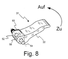
- a quick release device is provided, which among other things the counter flange 26, the clamping flange 28 and an actuating element 31 includes a pivot lever 32. By pressing of the actuator 31 is one between the counter flange 26 and the clamping flange 28 acting tension can be canceled.
- the quick release device has a coaxial in the Hollow spindle 24 arranged pressure piece 34.
- the pressure piece 34 has approximately the shape of a cup and is not by means of guides shown in more detail in a rotationally fixed manner, but in the axial direction movably guided in the hollow spindle 24.
- Inside is the pressure piece 34 is provided with an internal thread 36 into which a clamping bolt 40 can be screwed in with an external thread 38 is.
- the clamping bolt 40 is in turn fixed to the clamping flange 28 connected or executed in one piece with this.
- the a tight fit between the counter flange 26 and the Clamping flange 28 is caused by a bracing only schematically indicated disc spring assembly 42, which on one side on a rotating in the hollow spindle 24 Paragraph 44 attacks. Props on the opposite side the plate spring assembly 42 on the underside of the pressure piece 34 from. Because the top of the pressure piece 34 on a snap ring 45 strikes, the circumferential inside in the hollow spindle 24 Groove 46 is inserted, can from the pressure piece 34, the clamping bolt 40 and the clamping flange 28 unit formed only against the action of the plate spring assembly 42 in the direction the arrows labeled 48 are moved down.
- a lifting of the tension caused by the plate spring assembly 42 is only possible with the aid of the actuating element 31, by the pivot lever 32 formed thereon in the by the Arrow 50 shown direction from that shown in FIG. 1 Clamping position in a release position shown in Fig. 2 is transferred.
- the pivot lever 32 is firmly connected to an eccentric 52, which is rotatably mounted on a shaft 53 about an axis of rotation 54 is.
- a running surface forming the rolling surface of the eccentric 52 56 engages a cam 58 which is integral with a printhead 60 is formed.
- Printhead 60 is about the axis of rotation 25 rotatable in a self-lubricating bearing sleeve 62 axially movable added.
- a spiral compression spring 64 With the help of a spiral compression spring 64, the between an annular shoulder 66 of the printhead 60 and one Projection 68 of the housing 12 is held, the printhead 60 pressed against the tread 56 of the eccentric 52, so that the printhead 60 is always in contact with the actuator 31 stands.
- the Clamping flange 28 is not directly on the tool 30. Rather, it is based on the clamping flange 28 and the clamping bolt 40 unit formed, an intermediate flange 74 is rotatably received, that of a thin disc 76 and one from the center the disc 76 axially projecting projection 78. By the center of the disk 76 and the projection 78 is cylindrical Bore through which the clamping bolt 40 is guided.
- the attachment 78 has the shape of a regular polygon. This polygonal shape has its counterpart in the section the hollow spindle 24 below the plate spring assembly 42, the inside is also designed accordingly polygonal.
- the intermediate flange 74 with its extension 78 can thereby so insert into this section of the hollow spindle 24 that a Form fit between the hollow spindle 24 and the intermediate flange 74 is achieved.
- Mutual twisting of the hollow spindle 24 and intermediate flange 74 is then not in the release position possible.
- the tool is in the clamping position of the actuating element 31 30 between the counter flange 26 and the clamping flange 28 clamped.
- To create a positive connection between the Clamping flange 28 and the counter flange 26 in the clamping position ensure and thus a loosening of the clamping flange 28 under to avoid all operating conditions are preferably the mutually facing surfaces of the clamping flange 28 and intermediate flange 76 additionally with spur gears or similar Mistake. Consequently there is a continuous positive connection between the clamping flange 28 and the hollow spindle 24. Consequently it is not possible that the clamping flange 28 together with the Clamping pin 40 during use of the power tool Twisting releases from the pressure piece 34 by itself.
- the clamping flange 28 only slightly tightened until the clamping flange 28 on the intermediate flange 76 strikes because after tightening the clamping flange 28 is held non-rotatably in any case and that of the disc spring package 42 practiced tension practically independently is how far the clamping bolt 40 is screwed into the pressure piece 34 is.
- the clamping flange 28 Since the clamping flange 28 is opposite after releasing the bracing can easily rotate the intermediate flange 76, can the clamping bolt 40 is unscrewed from the pressure piece 34, even if the intermediate flange 74 is still with its shoulder 78 is held non-rotatably in the hollow spindle 24.
- One on the clamping bolt 40 put on snap ring 80 leads when unscrewing of the clamping bolt 40 with the intermediate flange 74 until this finally reached the position shown in Fig. 3.
- the clamping flange 28 can now, together with the intermediate flange 74 and the clamping bolt 40, completely in the direction of the arrows 48 are pulled out, causing the tool 30 from the counter flange 26 removed and replaced with a new tool can.
- the assembly is done in reverse order.
- the Eccentric 52 together with the cam 58 so that when the actuating element 31 in that shown in FIGS. 2 and 3 Release position, the actuator 31st automatically returned to the clamping position is as soon as the motor 16 of the power tool 10 in motion is set. Since in the release position the print head 60 to the Pressure piece 34 is pressed, is transmitted in the event of an unintentional Switching on the motor 16 a movement of the hollow spindle 24 about an existing frictional connection to it non-rotatably arranged pressure piece 34 and thus on the print head 60 and the cam 58 formed thereon Rotation of the printhead 60 causes stiction, between the cam 58 and that formed on the eccentric 52 Tread 56 acts in a much smaller Sliding friction passes.
- FIG. 4 shows the eccentric 52 and in solid lines the cam 58 formed on the pressure piece 60 in FIG. 1 shown clamping position.
- the pivot lever 32 is the overview not shown for the sake of it.
- the tread 56 of the eccentric 52nd describes in the embodiment shown in Fig. 4 the shape of a circular arc.
- the eccentricity denoted by e i.e. the vertical distance between the center point 55 of the Circular arc and the axis of rotation 54 of the eccentric 52 in the clamping position, determines the amount by which the eccentric rotates 52 the cam 58 is pressed down. With a turn of the eccentric 52 by 180 °, this dimension is 2e.
- Fig. 5 shows with solid lines the eccentric 52 in the Release position. Since the print head 60 from the plate spring assembly 42 in the direction indicated by arrow 84 pressed up a torque acts on the eccentric 52, which it in would like to move in the direction of arrow 86 into the clamping position. This torque arises because the cam 58 on the Eccentric 52 exerts a force that is not central to the axis of rotation Eccentric 52 is directed. Rather, there is between the Contact line along which the eccentric 52 and the cam 58 touch, and the axis of rotation 54 of the eccentric an offset v. This offset v creates a lever arm that corresponds to the one addressed Torque leads. In the above In the exemplary embodiment, the circular arc diameter is 12.6 mm, the eccentricity e 1.2 mm and the offset v 0.2 mm.
- the print head becomes 60 rotated together with the cam 58, so there is static friction between the tread 56 and the cam 58 into a sliding friction. If the cam 58 and the tread 56 are made of hardened ground steel, so the sliding friction is about an order of magnitude less than the static friction. The friction is no longer sufficient counteracting the torque exerted by the printhead, so that the eccentric 52 in the indicated by the arrow 86 Moved back towards the clamping position.
- FIG. 5 An eccentric 52 which is returned by approximately 60 ° is dashed in FIG. 5 indicated. It can be seen that the now In the direction of arrow 84 upward moving print head 60 the cams 58 formed thereon continue to have a torque exerts the eccentric 52, so that the actuating element 31 increasingly accelerates until it finally returns to that in FIG. 4 shown clamping position (or in a position shortly before) is transferred.
- Fig. 6 shows a rear view of the eccentric 52, in which can be seen that the eccentric 52 in the direction of the axis of rotation 54 of the eccentric is offset from the cam 58.
- the size of this offset is equal to the distance between the center plane 57 of the eccentric 52 and the axis of rotation 25 of the cam 58. Because of this offset, the line of contact between the eccentric 52 and cam 58 no longer symmetrical to the axis of rotation 25 of the cam 58 arranged.
- cam 58 rotates an additional torque on the eccentric 52 exercised, the direction of which depends on whether the cam 58 rotates clockwise or counterclockwise about its longitudinal axis 25.
- the cam rotates 58 in the direction indicated by arrow 59, whereby the Eccentric 52 in the direction of arrow 61 about its longitudinal axis 54 is moved back to the clamping position.
- Eccentric 52 seen in the direction of the axis of rotation 54, slightly conical is shaped. This also ensures that the contact line between the eccentric 52 and the cam 58, which are in this case shortened to a point of contact, not arranged more symmetrically to the axis of rotation 25 of the cam 58 is.
- the taper of the eccentric 52 can have values of approximately Accept 0.1 ° to 1 °, preferably of about 0.3 °.
- Both the eccentric 52 and the pressure pin 60 with the cam 58 preferably consist of sintered rolled steel parts, the Vickers hardness of which is in the range of approximately 64 and the roughness depth R z in the range of approximately 2 ⁇ m.
- this has the advantage that it creates a particularly large difference between static and sliding friction.
- the wear is low, so that the frictional relationships between the cam 58 and the running surface 56, which are decisive for the return of the actuating element 31, and on the other hand the stroke of the pressure pin 60 generated when the clamping lever 32 is pivoted remain constant over time.
- the plate spring assembly 42 when the plate spring assembly 42 generates a compressive force of approx. 3,000 N, the static friction force is approx. 300 N and the sliding friction force is approx. 40 N.
- a rolling surface of such a modified eccentric is plotted over the swivel angle ⁇ .
- This design of the rolling surface causes the actuating element 31 to first slowly move away from the released position after the motor is switched on and then accelerate more strongly. If desired, the final speed can be so great that the actuating element 31 finally transitions into an end position, in which it is sunk into a recess in the housing 12 of the power tool 10, by overcoming a latching resistance. With larger snap-in resistors, however, this can be inappropriate, since this may require such a great acceleration of the actuating element 31 that a danger to the user when swiveling back cannot be completely ruled out.
- the tread 56 can be influenced.
- the tread between a swivel angle of 0 ° and 60 ° is roughened such that due to the greater sliding friction there, the automatic swing back movement of the actuating element 31 braked or at least one further acceleration is counteracted.
- the cam 58 is formed on a printhead 60, the first in the course of the pivoting of the actuating element 31 on the Pressure piece 34 attacks.
- the eccentric 52 acts directly on the pressure piece 34. This must then be carried out so that it faces upwards the hollow spindle 24 protrudes.
- On the pressure piece 34 can additionally a cam 58 may be formed.
- the cam 58 can but here as well as in the embodiment explained above in the sense that the entire pressure piece 34th or the print head 60 is regarded as a cam.
- the parameters addressed are like this to determine that with a rotation of the pressure piece, the friction decreases at the contact surface, so that the rotary lever exclusively under the action of the elastic pressing elements from the Thread is unscrewed and thereby into its clamping position is returned. In this way, the rotary lever can be significantly return to the clamping position in a more controlled manner than if this is driven directly by the motor via a frictional connection becomes.
- the slider 100 is in the release position. If the print head 60 is now rotated, it is reduced , as already described above, between the Top side 106 of the print head 60 and the tread 102 of the Slider 100 acting friction force, whereby the print head 60th now slide the slider 100 back into the clamping position can push, as indicated by arrow 118.
- the tread 102 can of course be different Have slopes, as described above for FIG. 7 has been.
Landscapes
- Engineering & Computer Science (AREA)
- Mechanical Engineering (AREA)
- Jigs For Machine Tools (AREA)
- Grinding-Machine Dressing And Accessory Apparatuses (AREA)
- Clamps And Clips (AREA)
- Finish Polishing, Edge Sharpening, And Grinding By Specific Grinding Devices (AREA)
- Constituent Portions Of Griding Lathes, Driving, Sensing And Control (AREA)
- Transmission Devices (AREA)
- Gripping On Spindles (AREA)
Applications Claiming Priority (2)
| Application Number | Priority Date | Filing Date | Title |
|---|---|---|---|
| DE10039739 | 2000-08-16 | ||
| DE10039739A DE10039739A1 (de) | 2000-08-16 | 2000-08-16 | Elektrowerkzeug mit Schnellspanneinrichtung |
Publications (3)
| Publication Number | Publication Date |
|---|---|
| EP1180416A2 true EP1180416A2 (fr) | 2002-02-20 |
| EP1180416A3 EP1180416A3 (fr) | 2004-01-07 |
| EP1180416B1 EP1180416B1 (fr) | 2005-06-08 |
Family
ID=7652415
Family Applications (1)
| Application Number | Title | Priority Date | Filing Date |
|---|---|---|---|
| EP01119414A Expired - Lifetime EP1180416B1 (fr) | 2000-08-16 | 2001-08-11 | Outil électroportatif à dispositif de serrage rapide |
Country Status (4)
| Country | Link |
|---|---|
| US (1) | US6569001B2 (fr) |
| EP (1) | EP1180416B1 (fr) |
| AT (1) | ATE297292T1 (fr) |
| DE (2) | DE10039739A1 (fr) |
Cited By (14)
| Publication number | Priority date | Publication date | Assignee | Title |
|---|---|---|---|---|
| EP2213416A2 (fr) † | 2009-01-29 | 2010-08-04 | C. & E. Fein GmbH | Outil manuel à moteur doté d'un dispositif de serrage pour un outil |
| EP2213419A1 (fr) * | 2009-01-30 | 2010-08-04 | C. & E. Fein GmbH | Outil manuel à moteur doté d'un dispositif de serrage pour un outil |
| WO2012100894A1 (fr) * | 2011-01-25 | 2012-08-02 | Robert Bosch Gmbh | Dispositif de serrage d'outil |
| DE202011110131U1 (de) * | 2011-06-06 | 2013-02-11 | Robert Bosch Gmbh | Handwerkzeugmaschinenspannvorrichtung |
| CN103347653A (zh) * | 2011-01-25 | 2013-10-09 | 罗伯特·博世有限公司 | 刀具夹紧装置 |
| WO2013156306A1 (fr) * | 2012-04-17 | 2013-10-24 | C. & E. Fein Gmbh | Outil manuel comprenant un dispositif de serrage pour un outil |
| EP2799188A4 (fr) * | 2011-12-28 | 2015-08-12 | Positec Power Tools Suzhou Co | Outil électrique |
| CN106312954A (zh) * | 2015-06-26 | 2017-01-11 | 苏州宝时得电动工具有限公司 | 手持式工具及其夹紧装置 |
| WO2018072996A1 (fr) * | 2016-10-18 | 2018-04-26 | Robert Bosch Gmbh | Dispositif de fixation rapide pour machine-outil portative, en particulier une meuleuse d'angle, dotée d'au moins arbre de sortie susceptible d'être entraîné en rotation |
| CN108274435A (zh) * | 2017-01-06 | 2018-07-13 | 南京德朔实业有限公司 | 动力工具 |
| WO2019015980A1 (fr) * | 2017-07-20 | 2019-01-24 | Robert Bosch Gmbh | Dispositif de serrage rapide pour machine-outil portative |
| CN109877680A (zh) * | 2019-03-27 | 2019-06-14 | 深圳市贝优通新能源技术开发有限公司 | 一种用于建筑施工的可靠性高的磨光设备 |
| CN111761480A (zh) * | 2020-03-30 | 2020-10-13 | 浙江博来工具有限公司 | 一种快速夹紧装置及具有快速夹紧装置的角磨机 |
| CZ308718B6 (cs) * | 2020-06-29 | 2021-03-17 | Alexandr Filippov | Bruska pro broušení nože brusle |
Families Citing this family (65)
| Publication number | Priority date | Publication date | Assignee | Title |
|---|---|---|---|---|
| US7789737B2 (en) * | 2004-07-08 | 2010-09-07 | Metabowerke Gmbh | Rapid locking device |
| DE102004047280A1 (de) * | 2004-09-29 | 2006-04-06 | Hilti Ag | Werkzeuggerät zum aussermittigen Antrieb eines Werkzeuges |
| CA2530341A1 (fr) * | 2004-12-15 | 2006-06-15 | David Chandler Paul | Scie arasante |
| US10369718B2 (en) | 2004-12-15 | 2019-08-06 | Canis Major Tool Company Llc | Flush cut saw |
| US8087977B2 (en) | 2005-05-13 | 2012-01-03 | Black & Decker Inc. | Angle grinder |
| DE502005003376D1 (de) | 2005-11-28 | 2008-04-30 | Metabowerke Gmbh | Werkzeuggerät mit Schnellspanneinrichtung |
| AT503284B1 (de) * | 2006-03-21 | 2007-09-15 | Panhans Maschb Gmbh | Kreissägemaschine mit einspannvorrichtung für ein kreissägeblatt |
| EP2403685B1 (fr) * | 2008-01-07 | 2015-05-06 | Lachlan George Reid | Mécanisme de fixation pour un disque de coupe |
| US8408974B2 (en) * | 2009-07-14 | 2013-04-02 | Black & Decker Inc. | Adapter for abrasive cutting wheels |
| USD623034S1 (en) | 2009-12-18 | 2010-09-07 | Techtronic Power Tools Technology Limited | Tool arbor |
| USD619152S1 (en) | 2009-12-18 | 2010-07-06 | Techtronic Power Tools Technology Limited | Adapter |
| CN102107386B (zh) * | 2009-12-28 | 2014-01-01 | 泉峰(中国)贸易有限公司 | 砂光机 |
| CN102233537B (zh) * | 2010-04-27 | 2015-03-11 | 南京德朔实业有限公司 | 具有工作元件快速夹紧装置的手持动力工具 |
| US9073195B2 (en) | 2010-04-29 | 2015-07-07 | Black & Decker Inc. | Universal accessory for oscillating power tool |
| US9186770B2 (en) * | 2010-04-29 | 2015-11-17 | Black & Decker Inc. | Oscillating tool attachment feature |
| US8925931B2 (en) | 2010-04-29 | 2015-01-06 | Black & Decker Inc. | Oscillating tool |
| CN102416615B (zh) * | 2010-09-26 | 2014-07-30 | 南京德朔实业有限公司 | 具有工作元件快速夹紧装置的手持动力工具 |
| USD651062S1 (en) | 2010-09-29 | 2011-12-27 | Milwaukee Electric Tool Corporation | Tool interface for an accessory |
| USD653523S1 (en) | 2010-09-29 | 2012-02-07 | Milwaukee Electric Tool Corporation | Adapter for a tool |
| USD646542S1 (en) | 2010-09-29 | 2011-10-11 | Milwaukee Electric Tool Corporation | Accessory interface for a tool |
| CN102441876B (zh) * | 2010-10-09 | 2014-10-15 | 南京德朔实业有限公司 | 具有工作元件夹紧装置的动力工具 |
| US9149923B2 (en) | 2010-11-09 | 2015-10-06 | Black & Decker Inc. | Oscillating tools and accessories |
| CN102528768B (zh) * | 2010-12-07 | 2014-10-15 | 南京德朔实业有限公司 | 动力工具 |
| US9174354B2 (en) | 2011-05-18 | 2015-11-03 | Chevron (Hk) Limited | Power tool |
| CN102785161B (zh) * | 2011-05-18 | 2015-02-25 | 南京德朔实业有限公司 | 动力工具 |
| CN102259329B (zh) * | 2011-06-22 | 2013-08-21 | 南京德朔实业有限公司 | 多功能电动工具 |
| EP2762276B1 (fr) | 2011-09-29 | 2016-07-27 | Positec Power Tools (Suzhou) Co., Ltd | Machine multifonctionnelle |
| US9067293B2 (en) | 2011-09-30 | 2015-06-30 | Robert Bosch Gmbh | Accessory clamp for a power tool |
| JP2013094904A (ja) * | 2011-11-01 | 2013-05-20 | Makita Corp | 作業工具 |
| JP5746645B2 (ja) | 2012-02-03 | 2015-07-08 | 株式会社マキタ | 作業工具 |
| JP2013244553A (ja) * | 2012-05-24 | 2013-12-09 | Makita Corp | 作業工具 |
| USD832666S1 (en) | 2012-07-16 | 2018-11-06 | Black & Decker Inc. | Oscillating saw blade |
| US9486934B2 (en) * | 2012-11-23 | 2016-11-08 | Chervon (Hk) Limited | Accessory clamping mechanism and power tool having the same |
| US9339927B2 (en) * | 2012-12-29 | 2016-05-17 | Chervon (Hk) Limited | Accessory clamping mechanism and power tool having the same |
| US9956676B2 (en) * | 2013-01-09 | 2018-05-01 | Techtronic Power Tools Technology Limited | Tool with rotatable head |
| CN103111989B (zh) * | 2013-01-30 | 2015-05-20 | 南京久驰机电实业有限公司 | 一种多功能手持动力工具 |
| CN103963015B (zh) * | 2013-02-05 | 2016-03-16 | 苏州宝时得电动工具有限公司 | 动力工具 |
| US9555554B2 (en) | 2013-05-06 | 2017-01-31 | Milwaukee Electric Tool Corporation | Oscillating multi-tool system |
| JP6287205B2 (ja) * | 2013-12-27 | 2018-03-07 | 日立工機株式会社 | 動力作業機 |
| JP6400460B2 (ja) | 2014-01-30 | 2018-10-03 | 株式会社マキタ | 切断機 |
| CN104057411A (zh) * | 2014-06-28 | 2014-09-24 | 杨海蓉 | 一种夹紧装置 |
| US9475172B2 (en) | 2014-07-15 | 2016-10-25 | Milwaukee Electric Tool Corporation | Adjustable guard for power tool |
| USD744800S1 (en) | 2014-07-16 | 2015-12-08 | Milwaukee Electric Tool Corporation | Power tool blade guard |
| US11154974B2 (en) * | 2015-08-31 | 2021-10-26 | Positec Power Tools (Suzhou) Co., Ltd. | Hand-held tool and clamping device thereof |
| US10011036B2 (en) * | 2015-11-09 | 2018-07-03 | Robert Bosch Tool Corporation | Blade and blade attachment system for an oscillating tool |
| US10682736B2 (en) * | 2016-09-29 | 2020-06-16 | Black & Decker Inc. | Accessory clamp and spindle lock mechanism for power tool |
| DE102016220367A1 (de) * | 2016-10-18 | 2018-04-19 | Robert Bosch Gmbh | Schnellspannvorrichtung für eine zumindest eine rotierend antreibbare Abtriebswelle aufweisende tragbare Werkzeugmaschine, insbesondere Winkelschleifmaschine |
| USD814900S1 (en) | 2017-01-16 | 2018-04-10 | Black & Decker Inc. | Blade for oscillating power tools |
| US10265778B2 (en) | 2017-01-16 | 2019-04-23 | Black & Decker Inc. | Accessories for oscillating power tools |
| US10818450B2 (en) | 2017-06-14 | 2020-10-27 | Black & Decker Inc. | Paddle switch |
| DE102017214118A1 (de) * | 2017-08-11 | 2019-02-14 | Robert Bosch Gmbh | Schnellspannvorrichtung für eine, insbesondere zumindest eine rotierend antreibbare Abtriebswelle aufweisende, tragbare Werkzeugmaschine, insbesondere Winkelschleifmaschine |
| DE102017214117B4 (de) * | 2017-08-11 | 2026-02-26 | Robert Bosch Gmbh | Schnellspannvorrichtung |
| CN109986513A (zh) * | 2017-12-29 | 2019-07-09 | 宝时得科技(中国)有限公司 | 动力工具 |
| JP7096032B2 (ja) | 2018-03-28 | 2022-07-05 | 株式会社マキタ | マルチツール |
| JP7123633B2 (ja) * | 2018-06-01 | 2022-08-23 | 株式会社マキタ | 作業工具 |
| BR112021007485A2 (pt) * | 2018-10-19 | 2021-07-27 | Saint-Gobain Abrasives, Inc. | montagem de disco de retificação |
| US11052475B2 (en) * | 2018-11-27 | 2021-07-06 | Zhejiang Burley Tools Co., Ltd. | Rapid replacing structure for multi-purpose saw |
| DE102019131292A1 (de) * | 2019-11-20 | 2021-05-20 | Metabowerke Gmbh | Vorrichtung zum Einspannen eines Bearbeitungswerkzeugs in einem Elektrohandwerkzeuggerät |
| US11660690B2 (en) | 2019-11-28 | 2023-05-30 | Makita Corporation | Power tool |
| US11590593B2 (en) | 2019-11-28 | 2023-02-28 | Makita Corporation | Power tool |
| JP7422538B2 (ja) | 2019-12-26 | 2024-01-26 | 株式会社マキタ | 作業工具 |
| JP7330914B2 (ja) | 2020-02-13 | 2023-08-22 | 株式会社マキタ | 振動工具 |
| CN111941311A (zh) * | 2020-07-24 | 2020-11-17 | 中国航空工业集团公司沈阳飞机设计研究所 | 一种夹持固定结构 |
| CN114905465B (zh) * | 2021-02-10 | 2023-09-12 | 苏州宝时得电动工具有限公司 | 紧固机构及动力工具 |
| CN113878172B (zh) * | 2021-11-17 | 2024-11-15 | 浙江金美电动工具有限公司 | 电动工具的锯片快换结构及锯片快换方法 |
Family Cites Families (5)
| Publication number | Priority date | Publication date | Assignee | Title |
|---|---|---|---|---|
| EP0152564B1 (fr) * | 1984-02-18 | 1989-08-23 | C. & E. FEIN GmbH & Co. | Fixation d'outil |
| DE3523746A1 (de) * | 1985-07-03 | 1987-01-08 | Metabowerke Kg | Schnellspannvorrichtung fuer rotierende scheibenfoermige werkzeuge |
| DE3741484C1 (de) * | 1987-12-08 | 1989-08-24 | Fein C & E | Handwerkzeugmaschine mit automatischer Arretierung der Arbeitsspindel |
| DE59101383D1 (de) * | 1991-01-16 | 1994-05-19 | Fein C & E | Tragbare Schleifmaschine mit Schnellspanneinrichtung. |
| DE4336620C2 (de) * | 1993-10-27 | 1997-07-03 | Fein C & E | Elektrowerkzeug mit einer nur bei ausgeschaltetem Motor betätigbaren Spannvorrichtung |
-
2000
- 2000-08-16 DE DE10039739A patent/DE10039739A1/de not_active Withdrawn
-
2001
- 2001-08-11 DE DE50106436T patent/DE50106436D1/de not_active Expired - Lifetime
- 2001-08-11 EP EP01119414A patent/EP1180416B1/fr not_active Expired - Lifetime
- 2001-08-11 AT AT01119414T patent/ATE297292T1/de not_active IP Right Cessation
- 2001-08-16 US US09/931,706 patent/US6569001B2/en not_active Expired - Lifetime
Cited By (26)
| Publication number | Priority date | Publication date | Assignee | Title |
|---|---|---|---|---|
| EP2213416B1 (fr) * | 2009-01-29 | 2015-10-28 | C. & E. Fein GmbH | Outil manuel à moteur doté d'un dispositif de serrage pour un outil |
| EP2213416A2 (fr) † | 2009-01-29 | 2010-08-04 | C. & E. Fein GmbH | Outil manuel à moteur doté d'un dispositif de serrage pour un outil |
| EP2213419A1 (fr) * | 2009-01-30 | 2010-08-04 | C. & E. Fein GmbH | Outil manuel à moteur doté d'un dispositif de serrage pour un outil |
| US8317574B2 (en) | 2009-01-30 | 2012-11-27 | C. & E. Fein Gmbh | Power-driven hand tool with clamping fixture for a tool |
| US9463547B2 (en) | 2011-01-25 | 2016-10-11 | Robert Bosch Gmbh | Tool chucking device |
| CN103347653A (zh) * | 2011-01-25 | 2013-10-09 | 罗伯特·博世有限公司 | 刀具夹紧装置 |
| RU2601716C2 (ru) * | 2011-01-25 | 2016-11-10 | Роберт Бош Гмбх | Зажимное устройство для закрепления рабочего инструмента |
| WO2012100894A1 (fr) * | 2011-01-25 | 2012-08-02 | Robert Bosch Gmbh | Dispositif de serrage d'outil |
| DE202011110131U1 (de) * | 2011-06-06 | 2013-02-11 | Robert Bosch Gmbh | Handwerkzeugmaschinenspannvorrichtung |
| US9486909B2 (en) | 2011-06-06 | 2016-11-08 | Robert Bosch Gmbh | Clamping device for a hand-held power tool |
| EP2799188A4 (fr) * | 2011-12-28 | 2015-08-12 | Positec Power Tools Suzhou Co | Outil électrique |
| US9821430B2 (en) | 2011-12-28 | 2017-11-21 | Positec Power Tools (Suzhou) Co., Ltd. | Power tools |
| WO2013156306A1 (fr) * | 2012-04-17 | 2013-10-24 | C. & E. Fein Gmbh | Outil manuel comprenant un dispositif de serrage pour un outil |
| CN106312954A (zh) * | 2015-06-26 | 2017-01-11 | 苏州宝时得电动工具有限公司 | 手持式工具及其夹紧装置 |
| CN106312954B (zh) * | 2015-06-26 | 2021-08-10 | 苏州宝时得电动工具有限公司 | 手持式工具及其夹紧装置 |
| WO2018072996A1 (fr) * | 2016-10-18 | 2018-04-26 | Robert Bosch Gmbh | Dispositif de fixation rapide pour machine-outil portative, en particulier une meuleuse d'angle, dotée d'au moins arbre de sortie susceptible d'être entraîné en rotation |
| KR20190071710A (ko) * | 2016-10-18 | 2019-06-24 | 로베르트 보쉬 게엠베하 | 적어도 하나의 회전 구동 가능한 출력 샤프트를 구비한 휴대용 전동 공구, 특히 앵글 그라인더용 퀵 클램핑 장치 |
| US11607772B2 (en) | 2016-10-18 | 2023-03-21 | Robert Bosch Gmbh | Quick clamping device for at least one rotationally drivable drive shaft having a portable machine tool, in particular an angle grinding machine |
| CN108274435A (zh) * | 2017-01-06 | 2018-07-13 | 南京德朔实业有限公司 | 动力工具 |
| CN108274435B (zh) * | 2017-01-06 | 2020-12-01 | 南京德朔实业有限公司 | 动力工具 |
| WO2019015980A1 (fr) * | 2017-07-20 | 2019-01-24 | Robert Bosch Gmbh | Dispositif de serrage rapide pour machine-outil portative |
| US11717935B2 (en) | 2017-07-20 | 2023-08-08 | Robert Bosch Gmbh | Quick-clamping device for a portable machine tool |
| CN109877680A (zh) * | 2019-03-27 | 2019-06-14 | 深圳市贝优通新能源技术开发有限公司 | 一种用于建筑施工的可靠性高的磨光设备 |
| CN111761480A (zh) * | 2020-03-30 | 2020-10-13 | 浙江博来工具有限公司 | 一种快速夹紧装置及具有快速夹紧装置的角磨机 |
| CN111761480B (zh) * | 2020-03-30 | 2021-10-29 | 浙江博来工具有限公司 | 一种快速夹紧装置及具有快速夹紧装置的角磨机 |
| CZ308718B6 (cs) * | 2020-06-29 | 2021-03-17 | Alexandr Filippov | Bruska pro broušení nože brusle |
Also Published As
| Publication number | Publication date |
|---|---|
| US20020028644A1 (en) | 2002-03-07 |
| DE10039739A1 (de) | 2002-02-28 |
| EP1180416B1 (fr) | 2005-06-08 |
| EP1180416A3 (fr) | 2004-01-07 |
| ATE297292T1 (de) | 2005-06-15 |
| DE50106436D1 (de) | 2005-07-14 |
| US6569001B2 (en) | 2003-05-27 |
Similar Documents
| Publication | Publication Date | Title |
|---|---|---|
| EP1180416B1 (fr) | Outil électroportatif à dispositif de serrage rapide | |
| DE2741166C2 (de) | Vorrichtung zur Betätigung eines Spannkopfs | |
| DE3610569C2 (de) | Scheibenbremse für Fahrzeuge | |
| DE3205141C2 (fr) | ||
| EP2142042B1 (fr) | Moyens de fixation et procédé pour fixer un premier et un second composant | |
| EP3177839B1 (fr) | Boulon pour serrer des pièces placées l'une contre l'autre | |
| DE3727147A1 (de) | Nachspannendes bohrfutter | |
| DE102004020982A1 (de) | Kraftgetriebenes Handwerkzeug mit Spanneinrichtung für ein Werkzeug | |
| DE3784869T2 (de) | Hydraulische spannvorrichtung. | |
| EP0577981B1 (fr) | Tête pour une pièce à main médicale ou dentaire comportant un outil de traitement oscillant | |
| DE1477405C3 (de) | Einstellvorrichtung für Werkzeugträger, insbesondere für Bohrstangen von Feinbohrmaschinen mit einer drehbaren Bohrspindel | |
| DE2841116C2 (de) | Vorrichtung zum Abziehen von Hülsen, Lagerringen o.dgl. | |
| EP3658318B1 (fr) | Outil d'usinage par enlèvement de copeaux présentant un dispositif d'ajustement | |
| DE2908422C2 (de) | Hon- oder Läppkopf | |
| DE19508091C1 (de) | Stanzstempeleinheit | |
| DE3724232C2 (fr) | ||
| DE19701049C1 (de) | Radialwalzkopf | |
| EP0256289B1 (fr) | Appareil de pose d'éléments de fixation ou de boulons filetés | |
| DE1954337B2 (de) | Glattwalzwerkzeug für zylindrische Werkstückoberflächen | |
| DE2116233A1 (de) | Preßglattmaschine | |
| DE2339038C2 (de) | Vorrichtung zum Gewindestrehlen auf einer Drehmaschine | |
| DE2702211A1 (de) | Lenkrolle | |
| DE655217C (de) | Hahn, dessen Kueken vor der OEffnungsbewegung durch Drehen des Bedienungsgriffes vermittels Gewinde vom Sitz abgehoben bzw. nach der Schliessbewegung wieder auf den Sitz gepresst wird | |
| DE4025745C2 (fr) | ||
| DE1506473B1 (de) | Fangvorrichtung fuer Bau- und aehnliche Aufzuege |
Legal Events
| Date | Code | Title | Description |
|---|---|---|---|
| PUAI | Public reference made under article 153(3) epc to a published international application that has entered the european phase |
Free format text: ORIGINAL CODE: 0009012 |
|
| AK | Designated contracting states |
Kind code of ref document: A2 Designated state(s): AT BE CH CY DE DK ES FI FR GB GR IE IT LI LU MC NL PT SE TR |
|
| AX | Request for extension of the european patent |
Free format text: AL;LT;LV;MK;RO;SI |
|
| PUAL | Search report despatched |
Free format text: ORIGINAL CODE: 0009013 |
|
| AK | Designated contracting states |
Kind code of ref document: A3 Designated state(s): AT BE CH CY DE DK ES FI FR GB GR IE IT LI LU MC NL PT SE TR |
|
| AX | Request for extension of the european patent |
Extension state: AL LT LV MK RO SI |
|
| RAP1 | Party data changed (applicant data changed or rights of an application transferred) |
Owner name: C. & E. FEIN GMBH |
|
| 17P | Request for examination filed |
Effective date: 20040608 |
|
| AKX | Designation fees paid |
Designated state(s): AT BE CH CY DE DK ES FI FR GB GR IE IT LI LU MC NL PT SE TR |
|
| RAP1 | Party data changed (applicant data changed or rights of an application transferred) |
Owner name: C. & E. FEIN GMBH |
|
| GRAP | Despatch of communication of intention to grant a patent |
Free format text: ORIGINAL CODE: EPIDOSNIGR1 |
|
| GRAS | Grant fee paid |
Free format text: ORIGINAL CODE: EPIDOSNIGR3 |
|
| GRAA | (expected) grant |
Free format text: ORIGINAL CODE: 0009210 |
|
| AK | Designated contracting states |
Kind code of ref document: B1 Designated state(s): AT BE CH CY DE DK ES FI FR GB GR IE IT LI LU MC NL PT SE TR |
|
| PG25 | Lapsed in a contracting state [announced via postgrant information from national office to epo] |
Ref country code: TR Free format text: LAPSE BECAUSE OF FAILURE TO SUBMIT A TRANSLATION OF THE DESCRIPTION OR TO PAY THE FEE WITHIN THE PRESCRIBED TIME-LIMIT Effective date: 20050608 Ref country code: IE Free format text: LAPSE BECAUSE OF FAILURE TO SUBMIT A TRANSLATION OF THE DESCRIPTION OR TO PAY THE FEE WITHIN THE PRESCRIBED TIME-LIMIT Effective date: 20050608 Ref country code: ES Free format text: LAPSE BECAUSE OF FAILURE TO SUBMIT A TRANSLATION OF THE DESCRIPTION OR TO PAY THE FEE WITHIN THE PRESCRIBED TIME-LIMIT Effective date: 20050608 Ref country code: FI Free format text: LAPSE BECAUSE OF FAILURE TO SUBMIT A TRANSLATION OF THE DESCRIPTION OR TO PAY THE FEE WITHIN THE PRESCRIBED TIME-LIMIT Effective date: 20050608 |
|
| REG | Reference to a national code |
Ref country code: GB Ref legal event code: FG4D Free format text: NOT ENGLISH |
|
| REG | Reference to a national code |
Ref country code: CH Ref legal event code: EP |
|
| GBT | Gb: translation of ep patent filed (gb section 77(6)(a)/1977) |
Effective date: 20050608 |
|
| REF | Corresponds to: |
Ref document number: 50106436 Country of ref document: DE Date of ref document: 20050714 Kind code of ref document: P |
|
| REG | Reference to a national code |
Ref country code: IE Ref legal event code: FG4D Free format text: LANGUAGE OF EP DOCUMENT: GERMAN |
|
| REG | Reference to a national code |
Ref country code: SE Ref legal event code: TRGR |
|
| PG25 | Lapsed in a contracting state [announced via postgrant information from national office to epo] |
Ref country code: LU Free format text: LAPSE BECAUSE OF NON-PAYMENT OF DUE FEES Effective date: 20050811 Ref country code: AT Free format text: LAPSE BECAUSE OF NON-PAYMENT OF DUE FEES Effective date: 20050811 Ref country code: CY Free format text: LAPSE BECAUSE OF FAILURE TO SUBMIT A TRANSLATION OF THE DESCRIPTION OR TO PAY THE FEE WITHIN THE PRESCRIBED TIME-LIMIT Effective date: 20050811 |
|
| PG25 | Lapsed in a contracting state [announced via postgrant information from national office to epo] |
Ref country code: MC Free format text: LAPSE BECAUSE OF NON-PAYMENT OF DUE FEES Effective date: 20050831 Ref country code: BE Free format text: LAPSE BECAUSE OF NON-PAYMENT OF DUE FEES Effective date: 20050831 |
|
| PG25 | Lapsed in a contracting state [announced via postgrant information from national office to epo] |
Ref country code: GR Free format text: LAPSE BECAUSE OF FAILURE TO SUBMIT A TRANSLATION OF THE DESCRIPTION OR TO PAY THE FEE WITHIN THE PRESCRIBED TIME-LIMIT Effective date: 20050908 Ref country code: DK Free format text: LAPSE BECAUSE OF FAILURE TO SUBMIT A TRANSLATION OF THE DESCRIPTION OR TO PAY THE FEE WITHIN THE PRESCRIBED TIME-LIMIT Effective date: 20050908 |
|
| REG | Reference to a national code |
Ref country code: CH Ref legal event code: NV Representative=s name: TROESCH SCHEIDEGGER WERNER AG |
|
| PG25 | Lapsed in a contracting state [announced via postgrant information from national office to epo] |
Ref country code: PT Free format text: LAPSE BECAUSE OF FAILURE TO SUBMIT A TRANSLATION OF THE DESCRIPTION OR TO PAY THE FEE WITHIN THE PRESCRIBED TIME-LIMIT Effective date: 20051114 |
|
| REG | Reference to a national code |
Ref country code: IE Ref legal event code: FD4D |
|
| ET | Fr: translation filed | ||
| PLBE | No opposition filed within time limit |
Free format text: ORIGINAL CODE: 0009261 |
|
| STAA | Information on the status of an ep patent application or granted ep patent |
Free format text: STATUS: NO OPPOSITION FILED WITHIN TIME LIMIT |
|
| 26N | No opposition filed |
Effective date: 20060309 |
|
| BERE | Be: lapsed |
Owner name: C. & E. FEIN G.M.B.H. Effective date: 20050831 |
|
| PGFP | Annual fee paid to national office [announced via postgrant information from national office to epo] |
Ref country code: SE Payment date: 20120813 Year of fee payment: 12 |
|
| PGFP | Annual fee paid to national office [announced via postgrant information from national office to epo] |
Ref country code: FR Payment date: 20120823 Year of fee payment: 12 Ref country code: IT Payment date: 20120809 Year of fee payment: 12 |
|
| PGFP | Annual fee paid to national office [announced via postgrant information from national office to epo] |
Ref country code: NL Payment date: 20120809 Year of fee payment: 12 |
|
| REG | Reference to a national code |
Ref country code: NL Ref legal event code: V1 Effective date: 20140301 |
|
| REG | Reference to a national code |
Ref country code: SE Ref legal event code: EUG |
|
| PG25 | Lapsed in a contracting state [announced via postgrant information from national office to epo] |
Ref country code: NL Free format text: LAPSE BECAUSE OF NON-PAYMENT OF DUE FEES Effective date: 20140301 Ref country code: SE Free format text: LAPSE BECAUSE OF NON-PAYMENT OF DUE FEES Effective date: 20130812 |
|
| REG | Reference to a national code |
Ref country code: FR Ref legal event code: ST Effective date: 20140430 |
|
| PG25 | Lapsed in a contracting state [announced via postgrant information from national office to epo] |
Ref country code: IT Free format text: LAPSE BECAUSE OF NON-PAYMENT OF DUE FEES Effective date: 20130811 |
|
| PG25 | Lapsed in a contracting state [announced via postgrant information from national office to epo] |
Ref country code: FR Free format text: LAPSE BECAUSE OF NON-PAYMENT OF DUE FEES Effective date: 20130902 |
|
| PGFP | Annual fee paid to national office [announced via postgrant information from national office to epo] |
Ref country code: GB Payment date: 20160810 Year of fee payment: 16 Ref country code: CH Payment date: 20160812 Year of fee payment: 16 Ref country code: DE Payment date: 20160802 Year of fee payment: 16 |
|
| REG | Reference to a national code |
Ref country code: DE Ref legal event code: R119 Ref document number: 50106436 Country of ref document: DE |
|
| REG | Reference to a national code |
Ref country code: CH Ref legal event code: PL |
|
| GBPC | Gb: european patent ceased through non-payment of renewal fee |
Effective date: 20170811 |
|
| PG25 | Lapsed in a contracting state [announced via postgrant information from national office to epo] |
Ref country code: CH Free format text: LAPSE BECAUSE OF NON-PAYMENT OF DUE FEES Effective date: 20170831 Ref country code: LI Free format text: LAPSE BECAUSE OF NON-PAYMENT OF DUE FEES Effective date: 20170831 |
|
| PG25 | Lapsed in a contracting state [announced via postgrant information from national office to epo] |
Ref country code: DE Free format text: LAPSE BECAUSE OF NON-PAYMENT OF DUE FEES Effective date: 20180301 Ref country code: GB Free format text: LAPSE BECAUSE OF NON-PAYMENT OF DUE FEES Effective date: 20170811 |