EP1180441A1 - Schweisslose Befestigung eines Befestigungsbügels auf einem Behälterrohr eines Federbeines einer Aufhängungsanordnung - Google Patents
Schweisslose Befestigung eines Befestigungsbügels auf einem Behälterrohr eines Federbeines einer Aufhängungsanordnung Download PDFInfo
- Publication number
- EP1180441A1 EP1180441A1 EP01202660A EP01202660A EP1180441A1 EP 1180441 A1 EP1180441 A1 EP 1180441A1 EP 01202660 A EP01202660 A EP 01202660A EP 01202660 A EP01202660 A EP 01202660A EP 1180441 A1 EP1180441 A1 EP 1180441A1
- Authority
- EP
- European Patent Office
- Prior art keywords
- bracket
- reservoir tube
- strut assembly
- projections
- indentations
- Prior art date
- Legal status (The legal status is an assumption and is not a legal conclusion. Google has not performed a legal analysis and makes no representation as to the accuracy of the status listed.)
- Withdrawn
Links
- 239000000725 suspension Substances 0.000 title claims abstract description 16
- 238000007373 indentation Methods 0.000 claims abstract description 25
- 210000005069 ears Anatomy 0.000 claims description 5
- 238000003466 welding Methods 0.000 description 6
- 239000012530 fluid Substances 0.000 description 3
- 238000000034 method Methods 0.000 description 3
- 238000013016 damping Methods 0.000 description 2
- 238000004519 manufacturing process Methods 0.000 description 1
- 238000004080 punching Methods 0.000 description 1
Images


Classifications
-
- F—MECHANICAL ENGINEERING; LIGHTING; HEATING; WEAPONS; BLASTING
- F16—ENGINEERING ELEMENTS AND UNITS; GENERAL MEASURES FOR PRODUCING AND MAINTAINING EFFECTIVE FUNCTIONING OF MACHINES OR INSTALLATIONS; THERMAL INSULATION IN GENERAL
- F16F—SPRINGS; SHOCK-ABSORBERS; MEANS FOR DAMPING VIBRATION
- F16F9/00—Springs, vibration-dampers, shock-absorbers, or similarly-constructed movement-dampers using a fluid or the equivalent as damping medium
- F16F9/32—Details
- F16F9/54—Arrangements for attachment
-
- B—PERFORMING OPERATIONS; TRANSPORTING
- B60—VEHICLES IN GENERAL
- B60G—VEHICLE SUSPENSION ARRANGEMENTS
- B60G13/00—Resilient suspensions characterised by arrangement, location or type of vibration dampers
- B60G13/001—Arrangements for attachment of dampers
- B60G13/005—Arrangements for attachment of dampers characterised by the mounting on the axle or suspension arm of the damper unit
-
- B—PERFORMING OPERATIONS; TRANSPORTING
- B60—VEHICLES IN GENERAL
- B60G—VEHICLE SUSPENSION ARRANGEMENTS
- B60G15/00—Resilient suspensions characterised by arrangement, location or type of combined spring and vibration damper, e.g. telescopic type
- B60G15/02—Resilient suspensions characterised by arrangement, location or type of combined spring and vibration damper, e.g. telescopic type having mechanical spring
- B60G15/06—Resilient suspensions characterised by arrangement, location or type of combined spring and vibration damper, e.g. telescopic type having mechanical spring and fluid damper
- B60G15/07—Resilient suspensions characterised by arrangement, location or type of combined spring and vibration damper, e.g. telescopic type having mechanical spring and fluid damper the damper being connected to the stub axle and the spring being arranged around the damper
-
- B—PERFORMING OPERATIONS; TRANSPORTING
- B60—VEHICLES IN GENERAL
- B60G—VEHICLE SUSPENSION ARRANGEMENTS
- B60G2200/00—Indexing codes relating to suspension types
- B60G2200/10—Independent suspensions
- B60G2200/14—Independent suspensions with lateral arms
- B60G2200/142—Independent suspensions with lateral arms with a single lateral arm, e.g. MacPherson type
-
- B—PERFORMING OPERATIONS; TRANSPORTING
- B60—VEHICLES IN GENERAL
- B60G—VEHICLE SUSPENSION ARRANGEMENTS
- B60G2204/00—Indexing codes related to suspensions per se or to auxiliary parts
- B60G2204/10—Mounting of suspension elements
- B60G2204/12—Mounting of springs or dampers
- B60G2204/129—Damper mount on wheel suspension or knuckle
-
- B—PERFORMING OPERATIONS; TRANSPORTING
- B60—VEHICLES IN GENERAL
- B60G—VEHICLE SUSPENSION ARRANGEMENTS
- B60G2204/00—Indexing codes related to suspensions per se or to auxiliary parts
- B60G2204/40—Auxiliary suspension parts; Adjustment of suspensions
- B60G2204/43—Fittings, brackets or knuckles
- B60G2204/4304—Bracket for lower cylinder mount of McPherson strut
-
- B—PERFORMING OPERATIONS; TRANSPORTING
- B60—VEHICLES IN GENERAL
- B60G—VEHICLE SUSPENSION ARRANGEMENTS
- B60G2206/00—Indexing codes related to the manufacturing of suspensions: constructional features, the materials used, procedures or tools
- B60G2206/01—Constructional features of suspension elements, e.g. arms, dampers, springs
- B60G2206/40—Constructional features of dampers and/or springs
- B60G2206/41—Dampers
-
- B—PERFORMING OPERATIONS; TRANSPORTING
- B60—VEHICLES IN GENERAL
- B60G—VEHICLE SUSPENSION ARRANGEMENTS
- B60G2206/00—Indexing codes related to the manufacturing of suspensions: constructional features, the materials used, procedures or tools
- B60G2206/01—Constructional features of suspension elements, e.g. arms, dampers, springs
- B60G2206/40—Constructional features of dampers and/or springs
- B60G2206/42—Springs
- B60G2206/422—Accumulators for hydropneumatic springs
-
- B—PERFORMING OPERATIONS; TRANSPORTING
- B60—VEHICLES IN GENERAL
- B60G—VEHICLE SUSPENSION ARRANGEMENTS
- B60G2206/00—Indexing codes related to the manufacturing of suspensions: constructional features, the materials used, procedures or tools
- B60G2206/01—Constructional features of suspension elements, e.g. arms, dampers, springs
- B60G2206/80—Manufacturing procedures
- B60G2206/82—Joining
-
- B—PERFORMING OPERATIONS; TRANSPORTING
- B60—VEHICLES IN GENERAL
- B60G—VEHICLE SUSPENSION ARRANGEMENTS
- B60G2206/00—Indexing codes related to the manufacturing of suspensions: constructional features, the materials used, procedures or tools
- B60G2206/01—Constructional features of suspension elements, e.g. arms, dampers, springs
- B60G2206/80—Manufacturing procedures
- B60G2206/82—Joining
- B60G2206/8209—Joining by deformation
Definitions
- This invention relates to a vehicle suspension strut assembly in which the mounting bracket is secured to the reservoir tube by a mechanical interlock instead of by welding.
- Modern vehicles are commonly equipped with a strut suspension system in which a damper forms the primary link securing the vehicle body to the chassis.
- the damper includes a reservoir tube which is secured to a chassis component (such as a vehicle wheel end assembly) by a mounting bracket attached to the outer surface of the reservoir tube, which in the prior art is attached to the reservoir tube by welding.
- welding is a time consuming and equipment intensive process, and quality welds must be assured since all of the suspension forces are transferred through the joint between the reservoir tube and the mounting bracket. Accordingly, replacement of the prior art welded attachment between the reservoir tube and the mounting bracket with a mechanical interlock, which offers potential cost, quality and performance improvements.
- a mechanical interlock is provided between the attachment bracket and the reservoir tube of a suspension damper that eliminates the welded joint used to secure these components in the prior art.
- the attachment bracket includes a circumferentially extending portion that defines an inner circumferential surface that engages the outer circumferential surface of the reservoir tube with a force or interference fit.
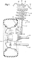
- a vehicle strut suspension system generally indicated by the numeral 10 includes a damper which includes a reservoir tube 12 which is secured to a non-rotating vehicle chassis component 14 by a bracket 13.
- the chassis component 14 rotatably mounts wheel 16 in a manner well known to those skilled in the art.
- a lower spring retainer 18 is secured to the reservoir tube 12, and a suspension spring 20 extends between the lower spring retainer 18 and an upper spring retainer 22, which is integral with the vehicle body indicated fragmentally at 24.
- the reservoir tube 12 is filled with damping fluid, and a piston (not shown) slides within the reservoir tube in response to normal movement of the vehicle. Fluid is metered across the piston in response to normal movements of the suspension system 10.
- the rod 26 is secured to the vehicle body 24 by a conventional fastener 30. Since the piston (not shown) is connected to the vehicle body by piston rod 26 and the reservoir tube 12 is secured to chassis component 14 by the bracket 13, the damper dampens relative movement between chassis component 14 and the vehicle body 24 since the damping fluid is metered across the piston.
- the lower steering rod 32 of the vehicle is secured to the chassis component 14 for steering the wheel 16, and a drive shaft 34 rotates relative to the chassis component 14 to drive the wheel 16.
- the reservoir tube 12 provides a part of the link controlling the wheel 16, and the bracket 13 must accordingly be rigidly secured to the reservoir tube 12.
- the know manner of securing the bracket to the reservoir tube was by welding, an inherently time consuming and equipment intensive process.
- a mechanical interlock is provided between the reservoir tube and the bracket, so that the welded attachment is eliminated, thus reducing manufacturing costs.
- the bracket 13 includes an outer bracket member 36 and an inner bracket member 38.
- Outer bracket member 36 includes a circumferentially extending portion 40 which terminates in contiguous ends 42, 44 which define a circumferentially extending gap 43 therebetween.
- a pair of attachment members 46,48 define an attachment portion of the bracket 13 and project outwardly from each of the contiguous ends 42,44.
- the attachment members 46, 48 define apertures 50, which receive fasteners 52 which extend across gap 43 between the attachment members 46,48 to secure the bracket to the chassis component 14.
- the circumferentially extending portion 40 further defines an outer circumferential surface 54 and an opposite inner circumferential surface 56.
- the reservoir tube 12 defines an outer circumferential surface 62, which has a diameter over which the circumferential portion 40 of the bracket 13 may be received with a force fit.
- the inner bracket member 38 includes an arcuate section 66 which is sized to be received within the gap 43 defined between the contiguous ends 42,44.
- a pair of ears 68,70 project from opposite ends of the arcuate section 66 and extend parallel to, and in engagement with, the attachment members 46,48.
- the ears 68,70 are provided with apertures 72 which register with the apertures 50 when the inner bracket member 38 is installed on the outer bracket member 36.
- Inner bracket member 38 is further provided with locating flanges 74, 76 and 78,80 which project from opposite ends of the ears 68,70 and which engage corresponding end surfaces 82,84 and 86,88 of the attachment members 46,48.
- the inner bracket member 38 is secured to the outer bracket 40 in any appropriate way, such as by spot welding.
- the bracket 13 is installed on the reservoir tube 12 by using an appropriate fixture to align the bracket and the reservoir and then forcing the bracket over the end of the reservoir tube. As discussed above, the diameters of the surfaces 56 and 62 are sized so that an interference or force fit is provided.
- multiple indentations 90 are formed in the outer circumferential surface 54 of the bracket 13, which form corresponding projections 92 on the inner circumferential surface 56 and corresponding indentations 94 in the outer circumferential surface 62 of the reservoir tube 12.
- the indentations and projections are aligned parallel to the axis defined by the circumferentially extending portion 40 and are formed by any appropriate process, such as punching.
- the reservoir tube 12 is installed on a mandrel before the indentations and projections are formed.
- the indentations 94 and projections 92 provide a mechanical interlock which meets or exceeds welding specifications with regard to relative axial or circumferential loads applied to the bracket 13 and reservoir tube 12.
- the indentations 90,94 and projections 92 are illustrated as being semispherical, the indentations and projections may be any suitable geometric shape (square, rectangular, oval, hexagonal, etc.) to optimize load carrying capacity and to facilitate attachment of the bracket to the reservoir tube.
Landscapes
- Engineering & Computer Science (AREA)
- Mechanical Engineering (AREA)
- General Engineering & Computer Science (AREA)
- Vehicle Body Suspensions (AREA)
- Fluid-Damping Devices (AREA)
Applications Claiming Priority (2)
| Application Number | Priority Date | Filing Date | Title |
|---|---|---|---|
| US63959600A | 2000-08-16 | 2000-08-16 | |
| US639596 | 2000-08-16 |
Publications (1)
| Publication Number | Publication Date |
|---|---|
| EP1180441A1 true EP1180441A1 (de) | 2002-02-20 |
Family
ID=24564774
Family Applications (1)
| Application Number | Title | Priority Date | Filing Date |
|---|---|---|---|
| EP01202660A Withdrawn EP1180441A1 (de) | 2000-08-16 | 2001-07-11 | Schweisslose Befestigung eines Befestigungsbügels auf einem Behälterrohr eines Federbeines einer Aufhängungsanordnung |
Country Status (1)
| Country | Link |
|---|---|
| EP (1) | EP1180441A1 (de) |
Cited By (4)
| Publication number | Priority date | Publication date | Assignee | Title |
|---|---|---|---|---|
| DE102005037737A1 (de) * | 2005-08-10 | 2007-02-22 | Schaeffler Kg | Anbindung eines Federbeins an einen Radträger eines Kraftfahrzeuges |
| JP2014502714A (ja) * | 2011-01-17 | 2014-02-03 | テネコ オートモティブ オペレーティング カンパニー インコーポレイテッド | ダンパーチューブ強化スリーブ |
| JP2014520239A (ja) * | 2011-06-23 | 2014-08-21 | テネコ オートモティブ オペレーティング カンパニー インコーポレイテッド | ダンパーチューブ強化スリーブ |
| WO2014168028A1 (ja) * | 2013-04-10 | 2014-10-16 | カヤバ工業株式会社 | ナックルブラケットの製造装置及び製造方法 |
Citations (4)
| Publication number | Priority date | Publication date | Assignee | Title |
|---|---|---|---|---|
| GB2137730A (en) * | 1983-04-09 | 1984-10-10 | Fichtel & Sachs Ag | Shock absorber-spring unit with stub axle mounting |
| US4484670A (en) * | 1981-02-13 | 1984-11-27 | Fichtel And Sachs Ag | Vibration damper arrangement particularly for a shock absorber strut |
| US5607035A (en) * | 1994-10-13 | 1997-03-04 | Delphi France Automotive Systems | Hydraulic damper |
| JPH0960682A (ja) * | 1995-08-28 | 1997-03-04 | Kayaba Ind Co Ltd | ブラケットの取付構造 |
-
2001
- 2001-07-11 EP EP01202660A patent/EP1180441A1/de not_active Withdrawn
Patent Citations (4)
| Publication number | Priority date | Publication date | Assignee | Title |
|---|---|---|---|---|
| US4484670A (en) * | 1981-02-13 | 1984-11-27 | Fichtel And Sachs Ag | Vibration damper arrangement particularly for a shock absorber strut |
| GB2137730A (en) * | 1983-04-09 | 1984-10-10 | Fichtel & Sachs Ag | Shock absorber-spring unit with stub axle mounting |
| US5607035A (en) * | 1994-10-13 | 1997-03-04 | Delphi France Automotive Systems | Hydraulic damper |
| JPH0960682A (ja) * | 1995-08-28 | 1997-03-04 | Kayaba Ind Co Ltd | ブラケットの取付構造 |
Non-Patent Citations (1)
| Title |
|---|
| PATENT ABSTRACTS OF JAPAN vol. 1997, no. 07 31 July 1997 (1997-07-31) * |
Cited By (7)
| Publication number | Priority date | Publication date | Assignee | Title |
|---|---|---|---|---|
| DE102005037737A1 (de) * | 2005-08-10 | 2007-02-22 | Schaeffler Kg | Anbindung eines Federbeins an einen Radträger eines Kraftfahrzeuges |
| JP2014502714A (ja) * | 2011-01-17 | 2014-02-03 | テネコ オートモティブ オペレーティング カンパニー インコーポレイテッド | ダンパーチューブ強化スリーブ |
| JP2014520239A (ja) * | 2011-06-23 | 2014-08-21 | テネコ オートモティブ オペレーティング カンパニー インコーポレイテッド | ダンパーチューブ強化スリーブ |
| WO2014168028A1 (ja) * | 2013-04-10 | 2014-10-16 | カヤバ工業株式会社 | ナックルブラケットの製造装置及び製造方法 |
| JP2014202344A (ja) * | 2013-04-10 | 2014-10-27 | カヤバ工業株式会社 | ナックルブラケットの製造装置及び製造方法 |
| TWI562840B (de) * | 2013-04-10 | 2016-12-21 | Kyb Corp | |
| EP2985490A4 (de) * | 2013-04-10 | 2017-01-11 | KYB Corporation | Vorrichtung und verfahren zur herstellung einer knöchelklammer |
Similar Documents
| Publication | Publication Date | Title |
|---|---|---|
| US8356826B2 (en) | Suspension system for a vehicle | |
| CA2791465C (en) | Rotatable bar pin bushing assembly | |
| EP2176079B1 (de) | Radachsenaufhängung | |
| CN101007499B (zh) | 铸造顶点可调v型扭矩杆 | |
| JP2975335B2 (ja) | 横荷重補償空気ばねストラットおよび横荷重補償方法 | |
| US6267526B1 (en) | Headed solid rod for torque rod spacer | |
| JP3994168B2 (ja) | トレーリングアームを一体に具備したリジッドアクスル | |
| US20110116731A1 (en) | Confined heavy duty bushing for high load applications | |
| US4491339A (en) | Strut for McPherson type automobile suspensions | |
| JP2005532228A5 (de) | ||
| US20100065998A1 (en) | Arrangement for retaining a compliance bush assembly | |
| EP1380451A2 (de) | Aufhängung mit gezogenen Lenkern | |
| CA2691602C (en) | Suspension system for a vehicle | |
| EP0083669B1 (de) | Federbein für Mcphersontyp-Fahrzeugaufhängungen | |
| EP1065077A1 (de) | Steckverbindung eines direkt wirkenden Endverbindungsgliedes für einen Stabilisatorstab | |
| JP2001182772A (ja) | 倒立型油圧緩衝器 | |
| CN105128600A (zh) | 桥壳、车桥、车辆和桥壳的制造方法 | |
| JPS6110025Y2 (de) | ||
| JPS5934487Y2 (ja) | 筒状ブッシュ組立体の抜け防止装置 | |
| JPH09210112A (ja) | 液圧緩衝器と支持部材付き取付ブラケットとの支持方法、および、それが用いられる支持構造 | |
| JP4695458B2 (ja) | ストラット型ショックアブソーバ | |
| JPH09164827A (ja) | 液圧緩衝器の取付ブッシュ | |
| JP2002195341A (ja) | ストラット型ショックアブソーバ |
Legal Events
| Date | Code | Title | Description |
|---|---|---|---|
| PUAI | Public reference made under article 153(3) epc to a published international application that has entered the european phase |
Free format text: ORIGINAL CODE: 0009012 |
|
| AK | Designated contracting states |
Kind code of ref document: A1 Designated state(s): AT BE CH CY DE DK ES FI FR GB GR IE IT LI LU MC NL PT SE TR |
|
| AX | Request for extension of the european patent |
Free format text: AL;LT;LV;MK;RO;SI |
|
| AKX | Designation fees paid | ||
| REG | Reference to a national code |
Ref country code: DE Ref legal event code: 8566 |
|
| STAA | Information on the status of an ep patent application or granted ep patent |
Free format text: STATUS: THE APPLICATION IS DEEMED TO BE WITHDRAWN |
|
| 18D | Application deemed to be withdrawn |
Effective date: 20020821 |