EP1180595A2 - Système d'alimentation en carburant - Google Patents
Système d'alimentation en carburant Download PDFInfo
- Publication number
- EP1180595A2 EP1180595A2 EP01117817A EP01117817A EP1180595A2 EP 1180595 A2 EP1180595 A2 EP 1180595A2 EP 01117817 A EP01117817 A EP 01117817A EP 01117817 A EP01117817 A EP 01117817A EP 1180595 A2 EP1180595 A2 EP 1180595A2
- Authority
- EP
- European Patent Office
- Prior art keywords
- fuel
- valve
- line
- pressure
- pump
- Prior art date
- Legal status (The legal status is an assumption and is not a legal conclusion. Google has not performed a legal analysis and makes no representation as to the accuracy of the status listed.)
- Granted
Links
Images







Classifications
-
- F—MECHANICAL ENGINEERING; LIGHTING; HEATING; WEAPONS; BLASTING
- F02—COMBUSTION ENGINES; HOT-GAS OR COMBUSTION-PRODUCT ENGINE PLANTS
- F02M—SUPPLYING COMBUSTION ENGINES IN GENERAL WITH COMBUSTIBLE MIXTURES OR CONSTITUENTS THEREOF
- F02M37/00—Apparatus or systems for feeding liquid fuel from storage containers to carburettors or fuel-injection apparatus; Arrangements for purifying liquid fuel specially adapted for, or arranged on, internal-combustion engines
- F02M37/0047—Layout or arrangement of systems for feeding fuel
- F02M37/0052—Details on the fuel return circuit; Arrangement of pressure regulators
-
- F—MECHANICAL ENGINEERING; LIGHTING; HEATING; WEAPONS; BLASTING
- F02—COMBUSTION ENGINES; HOT-GAS OR COMBUSTION-PRODUCT ENGINE PLANTS
- F02M—SUPPLYING COMBUSTION ENGINES IN GENERAL WITH COMBUSTIBLE MIXTURES OR CONSTITUENTS THEREOF
- F02M37/00—Apparatus or systems for feeding liquid fuel from storage containers to carburettors or fuel-injection apparatus; Arrangements for purifying liquid fuel specially adapted for, or arranged on, internal-combustion engines
- F02M37/20—Apparatus or systems for feeding liquid fuel from storage containers to carburettors or fuel-injection apparatus; Arrangements for purifying liquid fuel specially adapted for, or arranged on, internal-combustion engines characterised by means for preventing vapour lock
-
- F—MECHANICAL ENGINEERING; LIGHTING; HEATING; WEAPONS; BLASTING
- F02—COMBUSTION ENGINES; HOT-GAS OR COMBUSTION-PRODUCT ENGINE PLANTS
- F02M—SUPPLYING COMBUSTION ENGINES IN GENERAL WITH COMBUSTIBLE MIXTURES OR CONSTITUENTS THEREOF
- F02M63/00—Other fuel-injection apparatus having pertinent characteristics not provided for in groups F02M39/00 - F02M57/00 or F02M67/00; Details, component parts, or accessories of fuel-injection apparatus, not provided for in, or of interest apart from, the apparatus of groups F02M39/00 - F02M61/00 or F02M67/00; Combination of fuel pump with other devices, e.g. lubricating oil pump
- F02M63/02—Fuel-injection apparatus having several injectors fed by a common pumping element, or having several pumping elements feeding a common injector; Fuel-injection apparatus having provisions for cutting-out pumps, pumping elements, or injectors; Fuel-injection apparatus having provisions for variably interconnecting pumping elements and injectors alternatively
- F02M63/0225—Fuel-injection apparatus having a common rail feeding several injectors ; Means for varying pressure in common rails; Pumps feeding common rails
-
- F—MECHANICAL ENGINEERING; LIGHTING; HEATING; WEAPONS; BLASTING
- F04—POSITIVE - DISPLACEMENT MACHINES FOR LIQUIDS; PUMPS FOR LIQUIDS OR ELASTIC FLUIDS
- F04B—POSITIVE-DISPLACEMENT MACHINES FOR LIQUIDS; PUMPS
- F04B23/00—Pumping installations or systems
- F04B23/04—Combinations of two or more pumps
- F04B23/08—Combinations of two or more pumps the pumps being of different types
- F04B23/10—Combinations of two or more pumps the pumps being of different types at least one pump being of the reciprocating positive-displacement type
- F04B23/103—Combinations of two or more pumps the pumps being of different types at least one pump being of the reciprocating positive-displacement type being a radial piston pump
-
- F—MECHANICAL ENGINEERING; LIGHTING; HEATING; WEAPONS; BLASTING
- F04—POSITIVE - DISPLACEMENT MACHINES FOR LIQUIDS; PUMPS FOR LIQUIDS OR ELASTIC FLUIDS
- F04B—POSITIVE-DISPLACEMENT MACHINES FOR LIQUIDS; PUMPS
- F04B23/00—Pumping installations or systems
- F04B23/04—Combinations of two or more pumps
- F04B23/08—Combinations of two or more pumps the pumps being of different types
- F04B23/12—Combinations of two or more pumps the pumps being of different types at least one pump being of the rotary-piston positive-displacement type
-
- F—MECHANICAL ENGINEERING; LIGHTING; HEATING; WEAPONS; BLASTING
- F04—POSITIVE - DISPLACEMENT MACHINES FOR LIQUIDS; PUMPS FOR LIQUIDS OR ELASTIC FLUIDS
- F04B—POSITIVE-DISPLACEMENT MACHINES FOR LIQUIDS; PUMPS
- F04B49/00—Control, e.g. of pump delivery, or pump pressure of, or safety measures for, machines, pumps, or pumping installations, not otherwise provided for, or of interest apart from, groups F04B1/00 - F04B47/00
- F04B49/22—Control, e.g. of pump delivery, or pump pressure of, or safety measures for, machines, pumps, or pumping installations, not otherwise provided for, or of interest apart from, groups F04B1/00 - F04B47/00 by means of valves
- F04B49/24—Bypassing
-
- F—MECHANICAL ENGINEERING; LIGHTING; HEATING; WEAPONS; BLASTING
- F02—COMBUSTION ENGINES; HOT-GAS OR COMBUSTION-PRODUCT ENGINE PLANTS
- F02M—SUPPLYING COMBUSTION ENGINES IN GENERAL WITH COMBUSTIBLE MIXTURES OR CONSTITUENTS THEREOF
- F02M37/00—Apparatus or systems for feeding liquid fuel from storage containers to carburettors or fuel-injection apparatus; Arrangements for purifying liquid fuel specially adapted for, or arranged on, internal-combustion engines
- F02M37/04—Feeding by means of driven pumps
- F02M37/18—Feeding by means of driven pumps characterised by provision of main and auxiliary pumps
Definitions
- the invention relates to a fuel supply system for supplying fuel for an internal combustion engine according to the preamble of claim 1.
- German patent application DE 195 39 885 A1 shows one Fuel supply system at which to start the internal combustion engine a valve device ensures that the first fuel pump during the starting process Fuel with increased feed pressure to the fuel valves supplies. In many cases this is sufficient Feed pressure out to the internal combustion engine in no time to start. Due to the increased feed pressure, a possible gas bubble in the fuel connection between the first fuel pump and the second fuel pump in many cases are compressed so far that a more secure Operation of the internal combustion engine is guaranteed. Nevertheless it can be particularly high at temperatures during the Operation of the internal combustion engine and especially when the engine is turned off at high temperature problems with startup and also Problems operating the internal combustion engine during high temperatures come.
- the fuel supply system according to the invention with the characterizing features of claim 1 offers the advantageous Possibility with a particularly high heat load of the fuel in the fuel supply system, in particular but also with particularly high heat loads especially the second fuel pump to ensure that adequate heat dissipation from the lines of the Fuel supply system is made and that no gas bubbles arise within the lines.
- a particularly high heat load of the fuel in the fuel supply system in particular but also with particularly high heat loads especially the second fuel pump to ensure that adequate heat dissipation from the lines of the Fuel supply system is made and that no gas bubbles arise within the lines.
- Due to the closable shut-off valve the removal of the fuel via the flush line increased pressure in the fuel connection between the two fuel pumps so that an effective flushing is guaranteed and that it is also guaranteed that on Entrance to the second fuel pump no gas bubbles or Vapor bubbles occur.
- This will be advantageous reliably a drop in performance especially of the second Fuel pump reliable even at high temperatures prevented and even at high temperature is a reliable Guaranteed starting the engine.
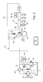
- FIG. 1 shows a first embodiment
- Figure 2 a second exemplary embodiment
- FIG. 3 a third exemplary embodiment
- 4 shows a detail
- FIG. 5 a fourth embodiment
- Figure 6 is a fifth 7, a sixth embodiment
- 8 shows a seventh embodiment
- the Figure 9 shows an eighth embodiment
- Figure 10 a Detailed view
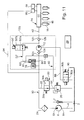
- Figure 11 is a ninth embodiment
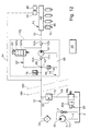
- FIG. 12 shows a tenth exemplary embodiment.
- the fuel supply system according to the invention Metering of fuel for an internal combustion engine can different types of internal combustion engines are used become. The same applies to the invention Method for operating an internal combustion engine.
- the internal combustion engine is, for example, a gasoline engine with an external one or internal mixture formation and spark ignition, whereby the Engine with a reciprocating piston (reciprocating piston engine) or with a rotatably mounted piston (Wankel piston engine) can be provided.
- the internal combustion engine can for example, a hybrid engine. With this engine with charge stratification, the fuel-air mixture in the Enriched the area of the spark plug so that a safe ignition is guaranteed, the combustion in the Medium but takes place when the mixture is very emaciated.
- the gas change in the combustion chamber of the internal combustion engine can for example, according to the four-stroke process or Two-stroke procedures take place.
- the combustion chamber of the internal combustion engine can be in a known manner Gas exchange valves (intake valves and exhaust valves) are provided his.
- the internal combustion engine can be designed that at least one fuel valve direct the fuel injected into the combustion chamber of the internal combustion engine.
- the Control of the performance of the internal combustion engine is carried out preferably by controlling the supply to the combustion chamber Amount of fuel. But it can also be provided that the fuel valve the fuel at the inlet valve Combustion chamber upstream.
- the for the Combustion of the fuel air supplied to the combustion chamber usually controlled with a throttle valve.
- About the Position of the throttle valve can be that of the internal combustion engine output to be controlled.
- the internal combustion engine has a cylinder, for example with a piston, or it can be with multiple cylinders and be provided with a corresponding number of pistons.
- a fuel valve is preferably provided for each cylinder.
- FIG. 1 shows a fuel reservoir 2, a suction line 4, a first fuel pump 6, a pressure relief valve 7, an electric motor 8, a fuel connection 10, a second fuel pump 12, a pressure line 14, four fuel valves 16 and a control device 20.
- the fuel valves 16 become often referred to in specialist circles as injectors or injectors.
- the first fuel pump 6 has a pressure side 6h and a suction side 6n.
- the second fuel pump 12 has one High pressure side 12h and a low pressure side 12n.
- the fuel connection 10 leads from the printing side 6h of the first Fuel pump 6 to the low pressure side 12n of the second Fuel pump 12. From the pressure side 6h of the first fuel pump 6 leads a channel back into the fuel tank 2.
- the pressure relief valve 7 is in this channel intended.
- a fuel line branches out of the fuel connection 10 22 from. Fuel can be supplied via the fuel line 22 from the fuel connection 10 into the fuel tank 2 can be returned. In the course of the fuel connection 10, between the first fuel pump 6 and the second fuel pump 12, there is a filter 24.
- a pressure control valve 26 and a shut-off valve 30 is provided in the fuel line 22 .
- the pressure control valve 26 and the shut-off valve 30 are effective one behind the other connected. That is, the pressure control valve 26 and the shutoff valve 30 are connected in series.
- the Pressure control valve 26 and valve device 30 can also compactly realized together in a common housing his.
- the shut-off valve 30 has a first switch position 30a and a second switch position 30b.
- first switch position 30a can fuel from the fuel connection 10 through the fuel line 22 via the pressure control valve 26 in the Flow fuel tank 2.
- the pressure control valve 26 determines the Feed pressure of the fuel in the fuel connection 10.
- the shut-off valve 30 is in its second switching position 30b, then the fuel cannot run out immediately the fuel connection 10 to the pressure control valve 26 flow.
- the first fuel pump 6 is powered by the electric motor 8 driven.
- the first fuel pump 6, the pressure relief valve 7, the electric motor 8, the filter 24, the pressure control valve 26 and the shut-off valve 30 are in the area of the fuel tank 2. These parts are preferably arranged on the outside of the fuel tank 2 or are inside the fuel tank Second
- the second is via mechanical transmission means 12m Fuel pump 12 mechanically with an output shaft Coupled internal combustion engine 32 coupled.
- the camshaft of the internal combustion engine 32 serves as Output shaft. Since the second fuel pump 12 is mechanical coupled to the output shaft of the internal combustion engine 32 is, the second fuel pump 12 operates in proportion to Speed of the output shaft of the internal combustion engine 32. Because the second fuel pump 12 is spatially close to the housing the engine 32 is flanged, becomes a strong one Heating the internal combustion engine 32 to the second fuel pump 12 transferred, which is a relatively high heat load of the fuel in the fuel supply system caused.
- a pressure sensor 48 is on the storage space 44 connected and senses the respective pressure of the fuel in the pressure line 14. According to this pressure, the pressure sensor 48 inputs electrical signal to the control device 20.
- Control device 20 electrically controllable control valve 50 connected. Depending on the control of the control valve 50 becomes fuel from the pressure line 14 via a circulation line 52 on the low pressure side 12n of the second fuel pump 12 headed. Between the control valve 50 and the Low pressure side 12n is a hydraulic resistance element arranged. The resistance element is a check valve 53, which is towards the fuel connection 10 opens at a very low pressure difference.
- the first fuel pump 6 is, for example a positive displacement pump driven by the electric motor 8, due to the design, a certain amount per revolution Fuel promotes.
- the pressure of the fuel on the pressure side 6h of the first fuel pump 6 is subsequently called Called supply pressure. Determined when the shut-off valve 30 is open the pressure control valve 26 the level of the feed pressure in the fuel connection 10.
- the pressure control valve 26 is for example set to a differential pressure of 3 bar. So the feed pressure in the fuel connection is 10 with the shut-off valve 30 open at three bar (3 bar).
- a purge line 60 leads from the second fuel pump 12 into the fuel tank 2.
- the flush line 60 Inside the pump housing 12g is the flush line 60 with the low pressure side 12n of the fuel pump 12, as in FIG. 4 recognizable.
- the hydraulic resistance will formed by a first overflow valve 61 and one second overflow valve 62.
- the junction branches at junction 63 Flush line 60 from circulation line 52.
- particularly advantageous and therefore preferably selected embodiment opens the flushing line 60 at an opening 64 between the shut-off valve 30 and the pressure control valve 26 into the fuel line 22.
- the first overflow valve 61 is at a relatively low level Differential pressure, preferably set to 1 bar.
- the second spill valve 62 is relative to one low differential pressure, preferably set to 1 bar. Because the differential pressure set on the two Overflow valves 61, 62 each chosen to be quite low can be advantageous for the overflow valves 61, 62 a fairly easy to manufacture design can be selected without causing strong scatter would result in the set differential pressure.
- the first fuel pump 6 usually delivers a little more Fuel into the fuel link 10 as from the second fuel pump 12 from the fuel connection 10 is removed. In normal operating condition, the flows excess fuel through the normally open Shut-off valve 30 and through the pressure control valve 26, so that in the fuel connection 10 which is due to the Differential pressure at the pressure control valve 26 adjusting feed pressure results.
- a sensor 65 detects that a particularly high Temperature prevails, then a corresponding signal is on the control device 20 is supplied.
- the control device 20 then switches the shut-off valve 30 in the second switch position 30b, in which the direct connection of the fuel connection 10 to the pressure control valve 26 is interrupted is.
- the shut-off valve 30 is closed, the excess, from the second fuel pump 12 from the Fuel connection 10 fuel not taken through the pump housing 12g of the second fuel pump 12 the first spill valve 61, through the second spill valve 62 and through the pressure control valve 26 back into the Fuel tank 2.
- the Shut-off valve 30 in fuel connection 10 a feed pressure that is the sum of the differential pressures of the Valves 61, 62 and 26 corresponds.
- the pressure relief valve 7, for example set to a pressure higher than the sum of the Differential pressures of valves 61, 62 and 26.
- the fuel pump 12 has a dashed line in the drawing Lines indicated pump housing 12g.
- the Overflow valves 61, 62, the check valve 53, the branch 63 and sensor 65 are preferably within of the pump housing 12g provided.
- the sensor 65 is, for example, a temperature sensor and it can, for example, directly in the pump housing 12g or in Area of the pressure line 14 may be arranged. To measure the Temperature can also be used instead of sensor 65, for example the water temperature of the cooling water of the internal combustion engine 32 can be used.
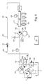
- FIG. 2 shows a further, preferably selected, particularly advantageous exemplary embodiment.
- the flush line 60 is in the in the embodiment shown downstream behind the second overflow valve 62 directly into the fuel tank 2 led.
- the differential pressure of the second overflow valve 62 is not, for example, 1 bar as in the first embodiment, but for example set to 5 bar.
- FIGS. 1 and 2 is an intermediate piece of the flushing line 60 between the first spill valve 61 and the second spill valve 62 merged with an intermediate piece of Circulation line 52 between the control valve 50 and the check valve 53.
- FIG. 3 shows a further, preferred selected, particularly advantageous exemplary embodiment.
- the flushing line 60 is an exemplary embodiment in FIG. 3 downstream behind the overflow valve 66 not with the Circulation line 52 merged. This gives you the The advantage that fewer valves are required. Nevertheless is also in the embodiment shown in Figure 3 at least indirect ventilation of the circulation line 52 via the check valve 53, via the low pressure side 12n of the fuel pump 12 and via the purge line 60 possible with the overflow valve 66.
- the differential pressure of the Overflow valve 66 set to 2 bar, for example.
- FIG. 4 shows a longitudinal section through the second fuel pump 12.
- the fuel pump 12 has at least one pump piston 12p.
- the fuel pump 12 preferably has three pump pistons 12p, of which for clarity only one is shown.
- the fuel gets through the Fuel connection 10 into the interior of the pump housing 12g.
- the low pressure side is located in the pump housing 12g 12n and the at least one pump piston 12p.
- the pump piston 12p is therefore surrounded by the fuel, the fuel has the same feed pressure as in the fuel connection 10.
- At the highest point on the inside of the housing 12g of the fuel pump 12 branches off the purge line 60. This ensures that the highest point Air collecting in the pump housing 12g through the flushing line 60 is discharged to the fuel tank 2.
- FIG. 5 shows a further, preferably selected, particularly advantageous exemplary embodiment.
- the pressure relief valve 7 is set to 8 bar, for example.
- the pressure relief valve 7 is, viewed in the direction of flow, before filter 24 to ensure that constipation at any point to any impermissible Overpressure in the fuel pump 6 leads.
- the check valve 53 has a biasing spring.
- the preload of the check valve 53 is on the flow resistance the throttle 70 tuned so that too then when the shut-off valve 30 is in its open switching position 30a stands, one from the circulation line 52 constantly desired amount of fuel via the flush line 60 and through the pressure control valve 26 to the fuel tank 2 flows.
- shut-off valve 30 When the shut-off valve 30 is in its closed switching position 30b stands, then it flows from the first fuel pump 6 promoted, but by the fuel valves 16 Excess fuel not taken off through the pressure relief valve 7 in the fuel tank 2, and a Part of the excess fuel flows through the throttle 70 and through the pressure control valve 26 to the fuel tank 2. Because the pressure at the pressure relief valve 7 is set higher than the differential pressure at the pressure control valve 26 and because of the flowing through the flush line 60 Fuel is also jammed at throttle 70, results in the fuel connection 10 when the valve is closed Shut-off valve 30 a feed pressure that is significantly higher than the one in normal operating condition with the shut-off valve open 30 occurring feed pressure.
- throttle 70 ensures that a certain proportion of the Fuel, this proportion being set accordingly Preload can be selected for the check valve 53 can, even in normal operation, continuously from the circulation line 52 is returned to the fuel tank 2.
- FIG. 6 shows a further, preferably selected, particularly advantageous exemplary embodiment.
- the overflow valve 72 is For example, it is set so that it is pending Differential pressure of 2 bar opens.
- the check valve 53 is set so that it is already very low differential pressure opens.
- shut-off valve 30 is in the closed switching position 30b switched. This increases the feed pressure in the fuel connection 10 to maximum to the pressure set on the pressure relief valve 7, and due to this increased feed pressure becomes the preload pressure of the Excess valve 72 exceeded, and fuel flows from the circulation line 52, via the overflow valve 72 and via the pressure control valve 26 into the fuel reservoir Second
- FIG. 7 shows a further, preferably selected, particularly advantageous exemplary embodiment.
- Deviating from the embodiment shown in FIG. 6 has what is symbolically represented in FIG Embodiment in the course of the circulation line 52 another hydraulic resistance element.
- the further Resistor element is a choke 74.
- the choke 74 is hydraulically in line with the check valve 53. Viewed in the direction of flow, the throttle can 74 are in front of or behind the check valve 53.
- the Throttle 74 and the check valve 53 are located downstream in terms of flow behind branch 63 to Flush line 60.
- the embodiment shown in FIG. 7 can do so be coordinated that at higher engine speed 32 part of the fuel from the circulation line 52 flows back into the fuel tank 2 without that by switching the shut-off valve 30 in its closed switch position 30b in the fuel connection 10 an increased feed pressure must be set.
- this has the advantage that at increased engine speed 32, which can occur frequently depending on the driving style the first fuel pump 6 does not counter an increased Feed pressure must work, which clearly shows their durability elevated.
- the shut-off valve 30 only for a short time, for example only for Flushing the fuel lines during the starting process Internal combustion engine 32, in the closed switching position 30b can be switched, which means that the fuel pump 6 only correspondingly rarely against an increased supply pressure Must work what the durability of the fuel pump 6 significantly extended.
- FIG. 8 shows a further, preferably selected, particularly advantageous exemplary embodiment.
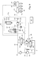
- FIG. 9 shows a further, preferably selected, particularly advantageous exemplary embodiment.
- FIG. 10 shows a detailed view of the exemplary embodiments shown in FIGS. 9, 11 and 12.
- the second fuel pump 12 has a pump piston 12p, an upstream check valve 12a output check valve 12b, a compression space 12k and a control valve 50 '.
- a pressure damper 78 is connected to the fuel connection 10 connected.
- the pressure damper 78 is preferably located inside the pump housing 12g.
- the resistance element is a check valve 80, that opens towards the fuel connection 10.
- At a Junction 82 opens the circulation line 52 'in the fuel connection 10.
- the circulation line 52 ' leads from the Compression chamber 12k, through the control valve 50 ', over the Branch 63 ', through the check valve 80 and over the Junction 82 in the fuel connection 10.
- the circulation line 52 ' runs a short distance immediately within of the pump housing 12g.
- the control valve 50 ' has an open one Switch position 50'a and a closed switch position 50'b.
- Has downstream downstream branch 63 ' the flush line 60 has hydraulic resistance.
- the hydraulic resistance is formed by a throttle 84.
- a line 86 leads from the fuel connection 10 into the Area of the piston guide of the piston 12p.
- the one about the Line 86 feed pressure supplied to the piston guide to reduce friction in the area of Piston guide.
- a leakage line 88 leads into the end of the pump piston 12p the fuel line 22. Downstream behind the pressure control valve 26 is in the fuel line 22 second shut-off valve 90.
- the second shut-off valve 90 has an open switch position 90a and a closed switch position 90b.
- the leakage line 88 opens between the Pressure control valve 26 and the second shut-off valve 90 an opening 92 in the fuel line 22.
- control valve 50 'during the pressure stroke in the open switch position 50'a stands, the fuel is due to the normally high pressure in the pressure line 14 over the open control valve 50 'through the circulation line 52' and over check valve 80 into fuel connection 10 promoted.
- the throttle 84 and the biased check valve 80 can be coordinated so that if during the pressure stroke, the control valve 50 'is open Part of the fuel flowing through the circulation line 52 ' through the flush line 60 and via the pressure control valve 26 in the fuel reservoir 2 flows back.
- Switching the control valve 50 'into the switch positions 50'a or 50'b can be that of the second fuel pump 12 fuel quantity delivered into the pressure line 14 to be controlled.
- By controlling the Control valve 50 'can from the fuel pump 12 in the Pressure line 14 delivered quantity can be controlled so that in the pressure line 14 the desired high pressure there is what can be sensed by the pressure sensor 48.
- the control valve 50 'driven depending on the pressure detected by the pressure sensor 48 the control valve 50 'driven.
- the pressure relief valve 96 is provided so that even with a Occurrence of an error, for example in the event of an error Working of the control valve 50 'in the pressure line 14 no dangerous overpressure can arise.
- the pressure relief valve 96 can also be electrically controllable, in such a way that that depending on the operating condition, the pressure in the Storage space 44 can be quickly reduced.
- shut-off valve 30 When the shut-off valve 30 is in its open switching position 30a stands, then flows, depending on how the throttle 84 and the pressure difference of the check valve 80 on each other are coordinated, for example only a very small part of the fuel flow flowing through the circulation line 52 ' via the flush line 60 into the fuel reservoir 2.
- the usually larger fuel flow flows through the Check valve 80 in the fuel connection 10, where the Pressure damper 78 is provided to the pulsating inflow Store fuel temporarily.
- the pressure relief valve 7 determines the Feed pressure in the fuel connection 10. Because the pressure relief valve 7 to a higher pressure than the pressure control valve 26 is set, the feed pressure is when closed Shut-off valve 30 higher than when the shut-off valve is open 30. With the switch position 30b closed Shut-off valve 30 flows out of the compression space 12k through the control valve 50 'flowing fuel flow in Essentially through the throttle 84, through the purge line 60 into the fuel line 22 and from there into the fuel tank Second
- the second is stopped while the internal combustion engine 32 is operating Shut-off valve 90 usually in its open switch position 90a. If the internal combustion engine 32 is switched off, then the second shut-off valve 90 is also closed Switch position 90b switched to thereby one premature pressure reduction in the low pressure system across the gap between the pump piston 12p and the pump housing 12g avoid.
- FIG. 11 shows a further, preferably selected, particularly advantageous exemplary embodiment.
- the leakage line 88 without shared use the fuel line 22 into the fuel tank 2 led.
- the leakage line 88 that is Shut-off valve 90 is provided. Because through the leakage line 88 only a very small amount of fuel flows that many times smaller than that through the fuel line 22 flowing fuel quantity is sufficient for the shut-off valve 90 a very small and very easy to manufacture Valve.
- FIG. 12 shows a further, preferably selected, particularly advantageous exemplary embodiment.
- the control valve 50 ' is via the circulation line 52' and over the junction 82 is connected to the fuel connection 10.
- the fuel can with the control valve 50 'open not only by the check valve 12a on the input side, but additionally also through the control valve 50 'into the compression space 12k flow.
- the control valve 50 ' will remain closed for so long Switch position 50'b held until in the pressure line 14 desired pressure is reached in each case.
- FIG. 12 there are two dash-dotted lines 98r and 98f shown. Usually they are to the left of the dash-dotted line 98r components shown in rear area of the motor vehicle, and the right of the broken line 98f components shown are usually located in the front area of the motor vehicle.
- the embodiments shown in Figures 1 to 8 are used especially when the second fuel pump 12 several pump pistons 12p, usually three pump pistons 12p.
- the embodiments shown in Figures 9 to 12 are used especially when the second fuel pump 12 a single pump piston 12p having.
Landscapes
- Engineering & Computer Science (AREA)
- Mechanical Engineering (AREA)
- General Engineering & Computer Science (AREA)
- Chemical & Material Sciences (AREA)
- Combustion & Propulsion (AREA)
- Fuel-Injection Apparatus (AREA)
- Output Control And Ontrol Of Special Type Engine (AREA)
Applications Claiming Priority (2)
| Application Number | Priority Date | Filing Date | Title |
|---|---|---|---|
| DE10039773A DE10039773A1 (de) | 2000-08-16 | 2000-08-16 | Kraftstoffversorgungsanlage |
| DE10039773 | 2000-08-16 |
Publications (4)
| Publication Number | Publication Date |
|---|---|
| EP1180595A2 true EP1180595A2 (fr) | 2002-02-20 |
| EP1180595A3 EP1180595A3 (fr) | 2003-04-23 |
| EP1180595B1 EP1180595B1 (fr) | 2005-06-15 |
| EP1180595B2 EP1180595B2 (fr) | 2011-02-23 |
Family
ID=7652439
Family Applications (1)
| Application Number | Title | Priority Date | Filing Date |
|---|---|---|---|
| EP01117817A Expired - Lifetime EP1180595B2 (fr) | 2000-08-16 | 2001-07-21 | Système d'alimentation en carburant |
Country Status (4)
| Country | Link |
|---|---|
| US (1) | US6792915B2 (fr) |
| EP (1) | EP1180595B2 (fr) |
| JP (1) | JP4739599B2 (fr) |
| DE (2) | DE10039773A1 (fr) |
Cited By (5)
| Publication number | Priority date | Publication date | Assignee | Title |
|---|---|---|---|---|
| EP1342912A3 (fr) * | 2002-03-07 | 2006-01-04 | Volkswagen Aktiengesellschaft | Système d'alimentation en carburant pour un moteur à combustion interne |
| US7341043B2 (en) | 2004-06-30 | 2008-03-11 | Toyota Jidosha Kabushiki Kaisha | Fuel supply system of internal combustion engine and internal combustion engine |
| EP1947321A4 (fr) * | 2005-10-28 | 2012-01-25 | Kazunori Yamamoto | Procede et circuit d'alimentation en carburant derive du petrole |
| WO2013102467A1 (fr) * | 2012-01-03 | 2013-07-11 | Volvo Lastvagnar Ab | Système de carburant et procédé correspondant |
| CN108488014A (zh) * | 2018-03-09 | 2018-09-04 | 安徽江淮汽车集团股份有限公司 | 一种燃油温度调节系统 |
Families Citing this family (53)
| Publication number | Priority date | Publication date | Assignee | Title |
|---|---|---|---|---|
| DE19954695A1 (de) * | 1999-11-13 | 2001-05-23 | Bosch Gmbh Robert | Kraftstoffeinspritzsystem |
| DE10205186A1 (de) * | 2002-02-08 | 2003-08-21 | Bosch Gmbh Robert | Kraftstoffeinspritzeinrichtung für eine Brennkraftmaschine |
| DE10261414B4 (de) * | 2002-12-30 | 2005-03-17 | Siemens Ag | Kraftstoffeinspritzanlage |
| US7682136B2 (en) * | 2003-03-28 | 2010-03-23 | Caterpillar Inc. | Multiple pump housing |
| JP4207834B2 (ja) * | 2003-06-27 | 2009-01-14 | 株式会社デンソー | 蓄圧式燃料噴射システム |
| JP2005090232A (ja) * | 2003-09-12 | 2005-04-07 | Hitachi Unisia Automotive Ltd | 内燃機関の燃料供給装置 |
| US7207319B2 (en) * | 2004-03-11 | 2007-04-24 | Denso Corporation | Fuel injection system having electric low-pressure pump |
| DE102004013307B4 (de) * | 2004-03-17 | 2012-12-06 | Robert Bosch Gmbh | Kraftstoffhochdruckpumpe mit einem Druckbegrenzungsventil |
| US7185634B2 (en) * | 2004-03-25 | 2007-03-06 | Sturman Industries, Inc. | High efficiency, high pressure fixed displacement pump systems and methods |
| ATE337483T1 (de) * | 2004-06-30 | 2006-09-15 | Fiat Ricerche | Kraftstoffdruckregelsystem für eine brennkraftmaschine |
| ATE394592T1 (de) * | 2004-11-12 | 2008-05-15 | Fiat Ricerche | Ein kraftstoffeinspritzsystem mit akkumulatorvolumen für eine brennkraftmaschine |
| DE102004062613B4 (de) * | 2004-12-24 | 2014-02-20 | Volkswagen Ag | Verfahren und Vorrichtung zur Kraftstoffversorgung von Verbrennungsmotoren |
| JP4552694B2 (ja) * | 2005-03-02 | 2010-09-29 | トヨタ自動車株式会社 | 車両の燃料供給装置 |
| DE102005027851A1 (de) * | 2005-06-16 | 2006-12-21 | Robert Bosch Gmbh | Kraftstoffeinspritzsystem für eine Brennkraftmaschine |
| US20070084431A1 (en) * | 2005-10-17 | 2007-04-19 | Omachi Steven T | Fluid pump and method |
| JP2007263064A (ja) * | 2006-03-29 | 2007-10-11 | Isuzu Motors Ltd | ジメチルエーテルエンジン搭載車両 |
| JP2007285235A (ja) * | 2006-04-18 | 2007-11-01 | Honda Motor Co Ltd | ディーゼルエンジンの燃料供給装置 |
| US7527043B2 (en) * | 2007-07-05 | 2009-05-05 | Caterpillar Inc. | Liquid fuel system with anti-drainback valve and engine using same |
| DE102007039892A1 (de) * | 2007-08-23 | 2009-02-26 | Continental Automotive Gmbh | Einspritzanlage für eine Brennkraftmaschine |
| US20090211559A1 (en) * | 2008-02-22 | 2009-08-27 | Andy Blaine Appleton | Engine fuel supply circuit |
| ATE487053T1 (de) * | 2008-03-04 | 2010-11-15 | Magneti Marelli Spa | Common rail direkteinspritzanordnung mit einem absperrventil zur steuerung der förderung einer hochdruckkraftstoffpumpe |
| JP4483979B2 (ja) * | 2008-05-15 | 2010-06-16 | 株式会社デンソー | 燃料供給装置 |
| US20170045005A9 (en) * | 2008-08-29 | 2017-02-16 | Delphi International Operations Luxembourg, S.A.R.L. | Fuel pressure regulation system |
| DE102008055935A1 (de) * | 2008-11-05 | 2010-05-12 | Continental Automotive Gmbh | Einspritzanlage für eine Brennkraftmaschine |
| JP4803269B2 (ja) * | 2009-02-24 | 2011-10-26 | 株式会社デンソー | 脈動低減装置 |
| DE102009027224A1 (de) | 2009-06-26 | 2010-12-30 | Robert Bosch Gmbh | Kraftstoffpumpe mit einem Fluidkanal zwischen einem Saugbereich und einem Druckbereich |
| ITMI20091355A1 (it) * | 2009-07-29 | 2011-01-30 | Bosch Gmbh Robert | Impianto di alimentazione carburante ad un motore a combustione interna |
| NL2003791C2 (nl) * | 2009-11-12 | 2011-05-16 | Vialle Alternative Fuel Systems Bv | Brandstoftoevoersysteem en hogedrukpomp voor een verbrandingsmotor. |
| AU2010200354A1 (en) * | 2010-02-01 | 2011-08-18 | Ford Motor Company Of Australia Limited | Liquid Fuel Injection Engine |
| US9541045B2 (en) * | 2010-07-14 | 2017-01-10 | Volvo Lastvagnar Ab | Fuel injection system with pressure-controlled bleed function |
| DE102010050560A1 (de) * | 2010-11-05 | 2012-05-10 | Volkswagen Ag | Kraftstoffhochdruckpumpe für eine Brennkraftmaschine mit Direkteinspritzung |
| CN103415694B (zh) * | 2010-12-22 | 2017-12-08 | 沃尔沃拉斯特瓦格纳公司 | 包括高压燃料喷射泵的燃料喷射系统 |
| US9316187B2 (en) * | 2011-01-18 | 2016-04-19 | Carter Fuel Systems, Llc | Diesel fuel system with advanced priming |
| JP2012167559A (ja) * | 2011-02-10 | 2012-09-06 | Denso Corp | 燃料噴射装置 |
| US9879662B2 (en) * | 2011-05-17 | 2018-01-30 | Holley Performance Products, Inc. | Inline pump assembly and method |
| DE102012203257A1 (de) * | 2012-03-01 | 2013-09-05 | Bayerische Motoren Werke Aktiengesellschaft | Betriebsverfahren für ein Brennkraftmaschinen-Kraftstoffsystem |
| JP6023456B2 (ja) * | 2012-04-12 | 2016-11-09 | 富士重工業株式会社 | 航空機燃料ポンプのエアロック防止システム及び航空機燃料ポンプのエアロック防止方法 |
| US20130312706A1 (en) * | 2012-05-23 | 2013-11-28 | Christopher J. Salvador | Fuel system having flow-disruption reducer |
| AT513154B1 (de) * | 2012-09-17 | 2014-02-15 | Bosch Gmbh Robert | Niederdruckkreislauf für ein Kraftstoffeinspritzsystem |
| CA2820013C (fr) * | 2013-06-28 | 2014-12-02 | Westport Power Inc. | Module de commande de la pression du carburant dans un moteur a combustion interne |
| US9388778B2 (en) * | 2013-07-19 | 2016-07-12 | Woodward, Inc. | Servo flow recirculation for an advanced thermal efficient aircraft engine fuel system |
| ITRM20130459A1 (it) * | 2013-08-05 | 2015-02-06 | Seko Spa | Pompa autocalibrante con ritorno a molla, in particolare pompa dosatrice autocalibrante con ritorno a molla |
| WO2015056045A1 (fr) * | 2013-10-14 | 2015-04-23 | Renault Trucks | Système d'alimentation en carburant destiné à un moteur à combustion interne |
| FR3013395B1 (fr) * | 2013-11-19 | 2015-12-11 | Renault Sas | Procede et systeme d'alimentation en gazole d'un vehicule automobile. |
| WO2016177431A1 (fr) * | 2015-05-07 | 2016-11-10 | Volvo Truck Corporation | Ensemble de pompe à carburant |
| US10208727B2 (en) * | 2015-12-28 | 2019-02-19 | Caterpillar Inc. | Fluid conditioning module |
| DE102016200232A1 (de) * | 2016-01-12 | 2017-07-13 | Continental Automotive Gmbh | Kraftstoffeinspritzsystem |
| DE102016204410A1 (de) * | 2016-03-17 | 2017-09-21 | Robert Bosch Gmbh | Verfahren zum Ermitteln eines Sollwertes für eine Stellgröße zur Ansteuerung einer Niederdruckpumpe |
| JP6862109B2 (ja) * | 2016-06-30 | 2021-04-21 | 住友建機株式会社 | ショベル |
| US11111923B2 (en) * | 2019-09-09 | 2021-09-07 | Mark Thomas Dorsey | System for priming a pool pump |
| DE112021005043T5 (de) * | 2020-10-26 | 2023-09-14 | Husqvarna Ab | Kraftstoffzufuhranordnung, Zweitaktmotor und angetriebenes Werkzeug |
| CN114183249B (zh) * | 2021-12-13 | 2023-09-05 | 中国船舶重工集团公司第七0三研究所 | 双燃料燃气轮机燃油供应系统 |
| JP7833065B1 (ja) * | 2025-02-10 | 2026-03-18 | ダイハツインフィニアース株式会社 | 内燃機関システム |
Family Cites Families (20)
| Publication number | Priority date | Publication date | Assignee | Title |
|---|---|---|---|---|
| DE4100973C1 (en) † | 1991-01-15 | 1992-07-16 | Pierburg Gmbh, 4040 Neuss, De | Fuel pump for IC engine - has electromotor driving two units, first delivering greater vol. and formed as side channel pump |
| JP3842331B2 (ja) * | 1995-05-26 | 2006-11-08 | ローベルト ボツシユ ゲゼルシヤフト ミツト ベシユレンクテル ハフツング | 内燃機関の燃料供給のための燃料供給装置及び内燃機関を運転する方法 |
| DE19539883B4 (de) † | 1995-05-26 | 2011-06-01 | Robert Bosch Gmbh | Kraftstoffversorgungsanlage und Verfahren zum Betreiben einer Brennkraftmaschine |
| DE19539885A1 (de) * | 1995-05-26 | 1996-11-28 | Bosch Gmbh Robert | Kraftstoffversorgungsanlage und Verfahren zum Betreiben einer Brennkraftmaschine |
| JP3939779B2 (ja) * | 1995-05-26 | 2007-07-04 | ローベルト ボツシユ ゲゼルシヤフト ミツト ベシユレンクテル ハフツング | 内燃機関の燃料供給のための燃料供給装置 |
| JP3333407B2 (ja) * | 1996-10-17 | 2002-10-15 | 株式会社ユニシアジェックス | 直噴式ガソリン内燃機関の燃料供給装置 |
| DE19652831B4 (de) † | 1996-12-18 | 2011-02-24 | Continental Automotive Gmbh | Druckfluid-Speisesystem für die Versorgung von Hochdruck-Sammelleitungen |
| DE19740057C1 (de) * | 1997-09-12 | 1999-01-21 | Mannesmann Vdo Ag | Kraftstoffversorgungssystem |
| JPH11200990A (ja) * | 1998-01-07 | 1999-07-27 | Unisia Jecs Corp | 燃料噴射制御装置 |
| DE19810867C2 (de) * | 1998-03-13 | 2000-02-24 | Bosch Gmbh Robert | Kraftstoffpumpen-Anordnung |
| DE19818421B4 (de) * | 1998-04-24 | 2017-04-06 | Robert Bosch Gmbh | Kraftstoffversorgungsanlage einer Brennkraftmaschine |
| DE19834120A1 (de) * | 1998-07-29 | 2000-02-03 | Bosch Gmbh Robert | Kraftstoffversorgungsanlage einer Brennkraftmaschine |
| DE19853823A1 (de) * | 1998-11-21 | 2000-05-25 | Bosch Gmbh Robert | Verfahren zum Betreiben einer Brennkraftmaschine insbesondere eines Kraftfahrzeugs |
| DE19909329A1 (de) † | 1999-03-03 | 2000-09-07 | Mannesmann Rexroth Ag | Kraftstoffeinspritzsystem |
| DE19933569B4 (de) † | 1999-07-16 | 2004-09-30 | Siemens Ag | Einspritzsystem für eine Brennkraftmaschine |
| DE19933567C1 (de) † | 1999-07-16 | 2001-02-01 | Siemens Ag | Einspritzsystem für eine Brennkraftmaschine |
| DE19937673A1 (de) † | 1999-08-10 | 2001-02-22 | Siemens Ag | Einspritzanlage für eine Brennkraftmaschine |
| DE19941689A1 (de) † | 1999-09-01 | 2001-03-15 | Siemens Ag | Einspritzanlage für eine Brennkraftmaschine |
| DE19941850B4 (de) † | 1999-09-02 | 2005-03-31 | Siemens Ag | Einspritzanlage für eine Brennkraftmaschine |
| DE10061987B4 (de) * | 2000-12-13 | 2005-06-16 | Robert Bosch Gmbh | Verfahren und Vorrichtung zum Kühlen einer Kraftstoffeinspritzanlage |
-
2000
- 2000-08-16 DE DE10039773A patent/DE10039773A1/de not_active Withdrawn
-
2001
- 2001-07-21 EP EP01117817A patent/EP1180595B2/fr not_active Expired - Lifetime
- 2001-07-21 DE DE50106502T patent/DE50106502D1/de not_active Expired - Lifetime
- 2001-08-13 US US09/928,862 patent/US6792915B2/en not_active Expired - Fee Related
- 2001-08-16 JP JP2001247246A patent/JP4739599B2/ja not_active Expired - Fee Related
Cited By (8)
| Publication number | Priority date | Publication date | Assignee | Title |
|---|---|---|---|---|
| EP1342912A3 (fr) * | 2002-03-07 | 2006-01-04 | Volkswagen Aktiengesellschaft | Système d'alimentation en carburant pour un moteur à combustion interne |
| US7341043B2 (en) | 2004-06-30 | 2008-03-11 | Toyota Jidosha Kabushiki Kaisha | Fuel supply system of internal combustion engine and internal combustion engine |
| DE102005028931B4 (de) * | 2004-06-30 | 2008-05-08 | Toyota Jidosha Kabushiki Kaisha, Toyota | Kraftstoffversorgungssystem für einen Verbrennungsmotor |
| EP1947321A4 (fr) * | 2005-10-28 | 2012-01-25 | Kazunori Yamamoto | Procede et circuit d'alimentation en carburant derive du petrole |
| WO2013102467A1 (fr) * | 2012-01-03 | 2013-07-11 | Volvo Lastvagnar Ab | Système de carburant et procédé correspondant |
| US9394857B2 (en) | 2012-01-03 | 2016-07-19 | Volvo Lastvagnar Ab | Fuel system and corresponding method |
| EP3135902A1 (fr) | 2012-01-03 | 2017-03-01 | AB Volvo Lastvagnar | Système de carburant et procédé correspondant |
| CN108488014A (zh) * | 2018-03-09 | 2018-09-04 | 安徽江淮汽车集团股份有限公司 | 一种燃油温度调节系统 |
Also Published As
| Publication number | Publication date |
|---|---|
| US6792915B2 (en) | 2004-09-21 |
| US20020092505A1 (en) | 2002-07-18 |
| JP2002098019A (ja) | 2002-04-05 |
| JP4739599B2 (ja) | 2011-08-03 |
| EP1180595A3 (fr) | 2003-04-23 |
| EP1180595B2 (fr) | 2011-02-23 |
| DE50106502D1 (de) | 2005-07-21 |
| DE10039773A1 (de) | 2002-02-28 |
| EP1180595B1 (fr) | 2005-06-15 |
Similar Documents
| Publication | Publication Date | Title |
|---|---|---|
| EP1180595B1 (fr) | Système d'alimentation en carburant | |
| DE102008045730B4 (de) | Rücklauffreie Kraftstoffpumpeneinheit sowie damit ausgerüstetes Fahrzeug | |
| DE19818421B4 (de) | Kraftstoffversorgungsanlage einer Brennkraftmaschine | |
| DE19539885A1 (de) | Kraftstoffversorgungsanlage und Verfahren zum Betreiben einer Brennkraftmaschine | |
| DE19539883B4 (de) | Kraftstoffversorgungsanlage und Verfahren zum Betreiben einer Brennkraftmaschine | |
| DE3112381C2 (fr) | ||
| DE4440205C2 (de) | Luft-Kraftstoff-System für eine Brennkraftmaschine mit Kraftstoffeinspritzung | |
| EP1306548B1 (fr) | Dispositif d'injection de carburant dont le réglage du débit est amélioré | |
| DE19652831B4 (de) | Druckfluid-Speisesystem für die Versorgung von Hochdruck-Sammelleitungen | |
| EP1296060B1 (fr) | Système d'injection de carburant pour un moteur à combustion interne | |
| DE19541086A1 (de) | Ventilanordnung für eine Einweg-Kraftstoffanlage | |
| CH674243A5 (fr) | ||
| DE19746563A1 (de) | Kraftstoffeinspritzeinrichtung für Brennkraftmaschinen | |
| DE112009000252T5 (de) | Brennstoffsystem zum Schutz eines Brennstofffilters | |
| EP2778381B1 (fr) | Système d'injection et procédé de fonctionnement d'un système d'injection | |
| DE3235413A1 (de) | Brennstoffeinspritzvorrichtung | |
| DE3011097A1 (de) | Kraftstoffeinspritzanlage fuer selbstzuendende brennkraftmaschinen | |
| DE10024268A1 (de) | Vorrichtung zur Benzindirekteinspritzung in einer Kolbenbrennkraftmaschine | |
| DE2924128A1 (de) | Einrichtung zur einspritzung von zuendkraftstoff einerseits und zuendunwilligem hauptkraftstoff andererseits fuer dieselmotoren | |
| DE2856595C2 (de) | Mehrzylinder-Dieselmotor mit einem Kraftstoffsteuerventil zur Zylinderschaltung | |
| DE102005033638A1 (de) | Kraftstoff-Fördereinrichtung, insbesondere für eine Brennkraftmaschine | |
| DE19753155A1 (de) | Kraftstoffversorgungssystem für eine Brennkraftmaschine und darin verwendete Hochdruckpumpe | |
| EP1361359B1 (fr) | Dispositif d'injection de carburant pour moteurs à combustion interne | |
| DE2513888B2 (de) | Mittels eines Abgasturboladers aufgeladene Viertakt-Brennkraftmaschine | |
| DE102007039893B4 (de) | Einspritzanlage für eine Brennkraftmaschine |
Legal Events
| Date | Code | Title | Description |
|---|---|---|---|
| PUAI | Public reference made under article 153(3) epc to a published international application that has entered the european phase |
Free format text: ORIGINAL CODE: 0009012 |
|
| AK | Designated contracting states |
Kind code of ref document: A2 Designated state(s): AT BE CH CY DE DK ES FI FR GB GR IE IT LI LU MC NL PT SE TR |
|
| AX | Request for extension of the european patent |
Free format text: AL;LT;LV;MK;RO;SI |
|
| PUAL | Search report despatched |
Free format text: ORIGINAL CODE: 0009013 |
|
| AK | Designated contracting states |
Designated state(s): AT BE CH CY DE DK ES FI FR GB GR IE IT LI LU MC NL PT SE TR |
|
| AX | Request for extension of the european patent |
Extension state: AL LT LV MK RO SI |
|
| RIC1 | Information provided on ipc code assigned before grant |
Ipc: 7F 02M 55/02 B Ipc: 7F 02M 63/02 B Ipc: 7F 02M 37/20 A Ipc: 7F 02M 69/46 B |
|
| 17P | Request for examination filed |
Effective date: 20031023 |
|
| AKX | Designation fees paid |
Designated state(s): DE FR GB |
|
| 17Q | First examination report despatched |
Effective date: 20031218 |
|
| GRAP | Despatch of communication of intention to grant a patent |
Free format text: ORIGINAL CODE: EPIDOSNIGR1 |
|
| GRAS | Grant fee paid |
Free format text: ORIGINAL CODE: EPIDOSNIGR3 |
|
| GRAA | (expected) grant |
Free format text: ORIGINAL CODE: 0009210 |
|
| AK | Designated contracting states |
Kind code of ref document: B1 Designated state(s): DE FR GB |
|
| PG25 | Lapsed in a contracting state [announced via postgrant information from national office to epo] |
Ref country code: GB Free format text: LAPSE BECAUSE OF FAILURE TO SUBMIT A TRANSLATION OF THE DESCRIPTION OR TO PAY THE FEE WITHIN THE PRESCRIBED TIME-LIMIT Effective date: 20050615 |
|
| REG | Reference to a national code |
Ref country code: GB Ref legal event code: FG4D Free format text: NOT ENGLISH |
|
| REF | Corresponds to: |
Ref document number: 50106502 Country of ref document: DE Date of ref document: 20050721 Kind code of ref document: P |
|
| GBV | Gb: ep patent (uk) treated as always having been void in accordance with gb section 77(7)/1977 [no translation filed] |
Effective date: 20050615 |
|
| PLBI | Opposition filed |
Free format text: ORIGINAL CODE: 0009260 |
|
| 26 | Opposition filed |
Opponent name: SIEMENS AG Effective date: 20060315 |
|
| PLAX | Notice of opposition and request to file observation + time limit sent |
Free format text: ORIGINAL CODE: EPIDOSNOBS2 |
|
| EN | Fr: translation not filed | ||
| PG25 | Lapsed in a contracting state [announced via postgrant information from national office to epo] |
Ref country code: FR Free format text: LAPSE BECAUSE OF FAILURE TO SUBMIT A TRANSLATION OF THE DESCRIPTION OR TO PAY THE FEE WITHIN THE PRESCRIBED TIME-LIMIT Effective date: 20060811 |
|
| PLAF | Information modified related to communication of a notice of opposition and request to file observations + time limit |
Free format text: ORIGINAL CODE: EPIDOSCOBS2 |
|
| PLAF | Information modified related to communication of a notice of opposition and request to file observations + time limit |
Free format text: ORIGINAL CODE: EPIDOSCOBS2 |
|
| PLBB | Reply of patent proprietor to notice(s) of opposition received |
Free format text: ORIGINAL CODE: EPIDOSNOBS3 |
|
| PG25 | Lapsed in a contracting state [announced via postgrant information from national office to epo] |
Ref country code: FR Free format text: LAPSE BECAUSE OF FAILURE TO SUBMIT A TRANSLATION OF THE DESCRIPTION OR TO PAY THE FEE WITHIN THE PRESCRIBED TIME-LIMIT Effective date: 20050731 |
|
| PG25 | Lapsed in a contracting state [announced via postgrant information from national office to epo] |
Ref country code: FR Free format text: LAPSE BECAUSE OF FAILURE TO SUBMIT A TRANSLATION OF THE DESCRIPTION OR TO PAY THE FEE WITHIN THE PRESCRIBED TIME-LIMIT Effective date: 20050615 |
|
| PLAY | Examination report in opposition despatched + time limit |
Free format text: ORIGINAL CODE: EPIDOSNORE2 |
|
| PLAH | Information related to despatch of examination report in opposition + time limit modified |
Free format text: ORIGINAL CODE: EPIDOSCORE2 |
|
| PUAH | Patent maintained in amended form |
Free format text: ORIGINAL CODE: 0009272 |
|
| STAA | Information on the status of an ep patent application or granted ep patent |
Free format text: STATUS: PATENT MAINTAINED AS AMENDED |
|
| 27A | Patent maintained in amended form |
Effective date: 20110223 |
|
| AK | Designated contracting states |
Kind code of ref document: B2 Designated state(s): DE FR GB |
|
| REG | Reference to a national code |
Ref country code: DE Ref legal event code: R102 Ref document number: 50106502 Country of ref document: DE Effective date: 20110223 |
|
| PGFP | Annual fee paid to national office [announced via postgrant information from national office to epo] |
Ref country code: DE Payment date: 20150925 Year of fee payment: 15 |
|
| REG | Reference to a national code |
Ref country code: DE Ref legal event code: R119 Ref document number: 50106502 Country of ref document: DE |
|
| PG25 | Lapsed in a contracting state [announced via postgrant information from national office to epo] |
Ref country code: DE Free format text: LAPSE BECAUSE OF NON-PAYMENT OF DUE FEES Effective date: 20170201 |