EP1180610A2 - Assemblage d'arbre d'entraínement et véhicule - Google Patents
Assemblage d'arbre d'entraínement et véhicule Download PDFInfo
- Publication number
- EP1180610A2 EP1180610A2 EP01117986A EP01117986A EP1180610A2 EP 1180610 A2 EP1180610 A2 EP 1180610A2 EP 01117986 A EP01117986 A EP 01117986A EP 01117986 A EP01117986 A EP 01117986A EP 1180610 A2 EP1180610 A2 EP 1180610A2
- Authority
- EP
- European Patent Office
- Prior art keywords
- drive shaft
- washer
- shaft assembly
- assembly according
- driver
- Prior art date
- Legal status (The legal status is an assumption and is not a legal conclusion. Google has not performed a legal analysis and makes no representation as to the accuracy of the status listed.)
- Granted
Links
- 238000012423 maintenance Methods 0.000 claims abstract description 4
- 238000005452 bending Methods 0.000 claims description 7
- 210000003746 feather Anatomy 0.000 claims description 4
- 238000004519 manufacturing process Methods 0.000 abstract description 4
- 239000012530 fluid Substances 0.000 description 3
- 241001417527 Pempheridae Species 0.000 description 1
- 230000000712 assembly Effects 0.000 description 1
- 238000000429 assembly Methods 0.000 description 1
- 230000005540 biological transmission Effects 0.000 description 1
- 230000007613 environmental effect Effects 0.000 description 1
- 230000003993 interaction Effects 0.000 description 1
- 239000000463 material Substances 0.000 description 1
- 230000002028 premature Effects 0.000 description 1
- 239000000565 sealant Substances 0.000 description 1
- 238000007789 sealing Methods 0.000 description 1
Images
Classifications
-
- F—MECHANICAL ENGINEERING; LIGHTING; HEATING; WEAPONS; BLASTING
- F16—ENGINEERING ELEMENTS AND UNITS; GENERAL MEASURES FOR PRODUCING AND MAINTAINING EFFECTIVE FUNCTIONING OF MACHINES OR INSTALLATIONS; THERMAL INSULATION IN GENERAL
- F16D—COUPLINGS FOR TRANSMITTING ROTATION; CLUTCHES; BRAKES
- F16D1/00—Couplings for rigidly connecting two coaxial shafts or other movable machine elements
- F16D1/06—Couplings for rigidly connecting two coaxial shafts or other movable machine elements for attachment of a member on a shaft or on a shaft-end
- F16D1/08—Couplings for rigidly connecting two coaxial shafts or other movable machine elements for attachment of a member on a shaft or on a shaft-end with clamping hub; with hub and longitudinal key
-
- Y—GENERAL TAGGING OF NEW TECHNOLOGICAL DEVELOPMENTS; GENERAL TAGGING OF CROSS-SECTIONAL TECHNOLOGIES SPANNING OVER SEVERAL SECTIONS OF THE IPC; TECHNICAL SUBJECTS COVERED BY FORMER USPC CROSS-REFERENCE ART COLLECTIONS [XRACs] AND DIGESTS
- Y10—TECHNICAL SUBJECTS COVERED BY FORMER USPC
- Y10T—TECHNICAL SUBJECTS COVERED BY FORMER US CLASSIFICATION
- Y10T74/00—Machine element or mechanism
- Y10T74/21—Elements
- Y10T74/2186—Gear casings
- Y10T74/2188—Axle and torque tubes
Definitions
- the invention relates to a drive shaft assembly for a Vehicle, with a gearbox, one of which Gearbox extending drive shaft and one on the drive shaft attachable and with this over a Tongue / feather key connection positively connectable hub of a Wheel assembly and a washer with at least one essentially flat, annular area with a central Cut-out for the drive shaft and one yourself of the area at least essentially in a right Angle-extending driver, as well as a vehicle.
- Vehicles for lawn, garden and property maintenance such as for example, lawn tractors usually have Drive wheels on which on a drive shaft by a Tongue / key connection are attached.
- the drive wheels or their hubs can often be free on the drive shaft slide and act as a pressure on a gearbox in one Area around the wave.
- a non-rotating one Washer which engages the gear housing between an end portion of the housing and the wheel or the Hub arranged to protect axle seals. After a long time The washer can wear out or wear through and no longer protect the seal. As soon as the Washer is worn out and seal damage gear fluid may be lost, resulting in costly gearbox damage can result.
- a possibility to solve the washer pressure wear problem consists of a second washer on the Arrange the drive shaft, which rotates with the shaft and rests on the non-rotating washer.
- the second is costly Washer on the rotating shaft by a Tongue / feather key connection to be defined because of the hubs or bearings must be machined to find suitable grooves for to provide a driver, which from the level of protruding rotating washer.
- washer can be found in US-A-5,846,001 be removed.
- a drive shaft assembly becomes Made available that is easy and inexpensive to manufacture is because there are no additional grooves or notches in the components have to be inserted to add a washer bring, together with the drive shaft or a hub To rotate the wheel assembly. Instead, an existing groove to accept the driver and thus to achieve a non-rotatable connection used.
- the groove is part of one Tongue / feather key connection, which is the hub on the drive shaft non-rotatably or positively. Such a groove is provided both in the drive shaft and in the hub.
- a second washer can be provided, which is not rotates with the drive shaft or the hub, but instead with the gearbox in a non-rotatable manner and Way is connected.
- Such a second washer closes off the gearbox housing and lays in it sealant contained or protects them from Environmental influences, so that leakage of Gear fluids is counteracted.
- the recess in the washer can vary be designed. Easy to put on and inexpensive Interaction with the drive shaft results especially with an at least substantially circular Design.
- the driver extends from the circumference of the washer away, an end face and the driver preferably form a substantially right angle. In this way the driver can be guided in the groove without an inclination for tilting or jamming.
- the driver is preferably at least essentially by the groove is added so that a compact arrangement is created and adjacent areas not by the additional component be affected.
- the washer usually has two at least in substantially flat end faces. Is the bending area or the bending point is designed such that he / she at least in the lies essentially between these end faces, he has little or no impact on adjacent Components.
- Such a drive shaft assembly can be different Vehicles. But it is particularly suitable for vehicles for lawn, garden and property maintenance, at which are, for example, ride-on mowers, lawn tractors, Sweepers, clearing devices etc. or hand-held devices can act.
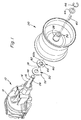
- the Axle gear 10 has a gear housing 12 with a End area 14 on.
- a drive shaft 16 extends from the End portion 14 outwardly about a transverse axis 18 to rotate.
- a wheel assembly 20 is connected to the drive shaft 16 connected by a keyway to the Rotate drive shaft 16 about axis 18.
- a (not shown) sealing arrangement in the end region 14 seals between the Drive shaft 16 and the gear housing 12 to gear fluids to prevent from the axle gear 10 withdraw.
- the drive shaft 16 has an axially extending notch or groove 26 and the wheel assembly 20 a hub 28 with a corresponding notch or groove 36, which with the groove 26th aligns when the wheel assembly 20 is on the drive shaft 16 is put on.
- a key 40 with a rectangular Cross-section that matches grooves 26 and 36 is in the grooves 26, 36 arranged to rotate the wheel assembly 20 with to force the drive shaft 16.
- the wheel assembly 20 can be in axial direction freely on the drive shaft 16 in such a way and way that slide through an inner end portion of the hub 28 pressure delivered to the end regions 14 of the transmission axis 12 becomes.
- a washer 44 holds together with one Circlip 46, which in a circumferential groove 48 on a End region of the drive shaft 16 fits the wheel assembly 20 the drive shaft 16.
- a fixed, L-shaped washer 50 via the drive shaft 16 against the gear housing 12 pushed.
- the washer 50 has a lower projection 52, which rests on the gear housing 12 by one Prevent rotation of the washer 50.
- a second Washer 60 via the drive shaft 16 against the outer Surface of the washer 50 pushed and forced with the hub 28 to rotate. The pressure forces are therefore over one distributed larger area, so that wear is reduced and both washers 50 and 60 have an increased tool life exhibit.
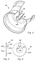
- the washer 60 has opposite inner and outer, flat end faces 60a and 60b and a central Recess 62 with a diameter that the Diameter of the drive shaft 16 slightly exceeds.
- On Carrier 64 extends from washer 60 in one Angle of 90 ° from the end face of the washer 60 the circumference of the recess 62 to the outside, with a lower Area 64a of driver 64 essentially on the circumference lies. As shown in Fig. 2, the driver engages 64 on inner end regions 36a of the existing groove 36 on and is essentially received in the groove 36. The driver 64 forces washer 60 to close with hub 28 rotate without doing a separate one in the inner end area the hub 28 required groove.
- Rounded notches 68 extend radially from the recess 62 on the sides of the driver 64 adjacent to the outside by an outward bending of the driver 64, while a strong Bending point is maintained, which a break in the Operation will resist.
- the arrangement ensures that the Washer 60 with a strong driver connection area can be manufactured without the bending point (see 64b in Fig. 3) from the planes of the opposite end faces of washers 60 protrudes, thereby providing an additional Groove in the hub 28 is avoided.
- the end face of the hub 28 is adjacent to the inner end region 36a on the end face 60a of the Washer 60 on.
- the driver 64 is by the End area 36a added so that the washer 60 with the wheel assembly 60 rotates when the final drive 10 Drive shaft 16 drives.
- the inner face 60a of the Washer 60 rotates relative to the outer face the fixed washer 50 to the compressive forces over to distribute a relatively large area so that Wear is reduced.
Landscapes
- Engineering & Computer Science (AREA)
- General Engineering & Computer Science (AREA)
- Mechanical Engineering (AREA)
- General Details Of Gearings (AREA)
- Sliding-Contact Bearings (AREA)
- Motor Power Transmission Devices (AREA)
- Arrangement And Driving Of Transmission Devices (AREA)
Applications Claiming Priority (2)
| Application Number | Priority Date | Filing Date | Title |
|---|---|---|---|
| US09/634,189 US6467853B1 (en) | 2000-08-09 | 2000-08-09 | Keyed anti-wear thrust washer structure |
| US634189 | 2000-08-09 |
Publications (3)
| Publication Number | Publication Date |
|---|---|
| EP1180610A2 true EP1180610A2 (fr) | 2002-02-20 |
| EP1180610A3 EP1180610A3 (fr) | 2004-04-07 |
| EP1180610B1 EP1180610B1 (fr) | 2006-07-26 |
Family
ID=24542769
Family Applications (1)
| Application Number | Title | Priority Date | Filing Date |
|---|---|---|---|
| EP01117986A Expired - Lifetime EP1180610B1 (fr) | 2000-08-09 | 2001-07-25 | Assemblage d'arbre d'entraînement et véhicule |
Country Status (4)
| Country | Link |
|---|---|
| US (1) | US6467853B1 (fr) |
| EP (1) | EP1180610B1 (fr) |
| CA (1) | CA2351459C (fr) |
| DE (1) | DE50110527D1 (fr) |
Cited By (1)
| Publication number | Priority date | Publication date | Assignee | Title |
|---|---|---|---|---|
| EP2853763A1 (fr) * | 2013-09-26 | 2015-04-01 | Sypris Technologies, Inc. | Ensemble et arbre d'essieu |
Families Citing this family (11)
| Publication number | Priority date | Publication date | Assignee | Title |
|---|---|---|---|---|
| US7000995B2 (en) * | 2003-04-16 | 2006-02-21 | George Allan Hagelthorn | High-integrity interlocking nut and washer system |
| US6948782B2 (en) * | 2003-05-21 | 2005-09-27 | The Toro Company | Wheel hub assemblies with anti-rotate feature for use with zero-radius-turning vehicle |
| US8668206B2 (en) * | 2009-06-11 | 2014-03-11 | Mueller International, Llc | Face seal gasket |
| US8393266B2 (en) * | 2009-07-20 | 2013-03-12 | Lifestyle Crafts, Llc | Systems and methods applying a design on a medium |
| IT1399486B1 (it) * | 2010-03-31 | 2013-04-19 | Ima Safe S R L | Perfezionamenti ai gruppi distributori e gruppo distributore perfezionato |
| CN105027397B (zh) * | 2013-03-04 | 2017-10-10 | 冲微型技研株式会社 | 旋转致动器与被驱动体的联结构造 |
| US20180037057A1 (en) * | 2016-08-04 | 2018-02-08 | Peter J. Nordine | Safety device for a vehicle wheel |
| US10850750B2 (en) * | 2017-07-04 | 2020-12-01 | Standard Car Truck Company | Vehicle draft key wear protector |
| US10781911B2 (en) | 2018-09-13 | 2020-09-22 | Cnh Industrial America Llc | Planetary gear assembly |
| US10975909B1 (en) | 2020-02-03 | 2021-04-13 | George A. Hagelthorn | System and method to precisely adjust tapered roller bearings using a four-piece jam nut configuration |
| US12060722B2 (en) * | 2022-05-19 | 2024-08-13 | National Flooring Equipment, Inc. | Wheel coupler and scraper for floor stripper |
Family Cites Families (11)
| Publication number | Priority date | Publication date | Assignee | Title |
|---|---|---|---|---|
| US1086343A (en) * | 1909-12-04 | 1914-02-10 | Ferro Concrete Construction Company | Form work for concrete construction. |
| US1211553A (en) * | 1916-08-12 | 1917-01-09 | Meho Dervoz | Nut-lock. |
| US1580015A (en) * | 1923-12-03 | 1926-04-06 | Glen G Clark | Lock washer |
| US3376714A (en) * | 1966-02-28 | 1968-04-09 | Gen Motors Corp | Clutch assembly |
| US4191872A (en) * | 1979-03-14 | 1980-03-04 | Carlingswitch, Inc. | Switch case with stackable lock washer |
| US5795037A (en) * | 1994-03-01 | 1998-08-18 | Hub Nut Corporation | Controlled position axle nut system and method to preload tapered roller bearings |
| US5573311A (en) * | 1994-07-05 | 1996-11-12 | Warn Industries, Inc. | Anti-rotation device for wheel spindle nut |
| US5618143A (en) * | 1994-11-02 | 1997-04-08 | Warn Industries, Inc. | Spindle nut and locking device |
| US5772373A (en) * | 1994-11-02 | 1998-06-30 | Warn Industries, Inc. | Nut and locking device |
| US6122996A (en) * | 1998-11-20 | 2000-09-26 | Hydro-Gear Limited Partnership | Hydrostatic transmission |
| DE19710868A1 (de) | 1997-03-15 | 1998-09-17 | Schaeffler Waelzlager Ohg | Axiallagerscheibe |
-
2000
- 2000-08-09 US US09/634,189 patent/US6467853B1/en not_active Expired - Lifetime
-
2001
- 2001-06-22 CA CA002351459A patent/CA2351459C/fr not_active Expired - Fee Related
- 2001-07-25 EP EP01117986A patent/EP1180610B1/fr not_active Expired - Lifetime
- 2001-07-25 DE DE50110527T patent/DE50110527D1/de not_active Expired - Lifetime
Cited By (2)
| Publication number | Priority date | Publication date | Assignee | Title |
|---|---|---|---|---|
| EP2853763A1 (fr) * | 2013-09-26 | 2015-04-01 | Sypris Technologies, Inc. | Ensemble et arbre d'essieu |
| US9296258B2 (en) | 2013-09-26 | 2016-03-29 | Sypris Technologies, Inc. | Axle shaft and assembly |
Also Published As
| Publication number | Publication date |
|---|---|
| CA2351459A1 (fr) | 2002-02-09 |
| EP1180610B1 (fr) | 2006-07-26 |
| EP1180610A3 (fr) | 2004-04-07 |
| DE50110527D1 (de) | 2006-09-07 |
| CA2351459C (fr) | 2004-10-19 |
| US6467853B1 (en) | 2002-10-22 |
Similar Documents
| Publication | Publication Date | Title |
|---|---|---|
| DE2822686C2 (fr) | ||
| DE3427577C2 (fr) | ||
| EP1180610B1 (fr) | Assemblage d'arbre d'entraînement et véhicule | |
| EP0219683B1 (fr) | Dispositif d'étanchéité | |
| EP0926046A2 (fr) | Dispositif d'entrée d'un angle de direction pour véhicules | |
| DE19843946A1 (de) | Riemenscheibeneinheit | |
| AT524089B1 (de) | Radantriebsmodul mit einem in dem Radantriebsmodul aufgenommenen Rad | |
| DE19547980A1 (de) | Differentialgetriebe | |
| DE2350171A1 (de) | Drehmomentverteilergetriebe | |
| DE3203648A1 (de) | Torsionsdaempfungsvorrichtung, insbesondere reibkupplung fuer kraftfahrzeuge | |
| DE2848486C2 (fr) | ||
| DE3237809A1 (de) | Reibkupplung, insbesondere fuer kraftfahrzeuge | |
| DE10156041A1 (de) | Hydrodynamische Kopplungseinrichtung | |
| DE3317532A1 (de) | Torsionsdaempfungsvorrichtung, insbesondere reibungskupplung fuer kraftfahrzeuge | |
| DE4101705A1 (de) | Handgefuehrte elektrowerkzeugmaschine | |
| DE1675234A1 (de) | Reibkupplung mit Daempfungsnabe | |
| AT413747B (de) | Winkelgetriebe mit integrierter drehspielkupplung | |
| DE602004001805T2 (de) | Apparatus und Herstellungsverfahren eines Differentialgetriebes für Fahrzeuge mit einem Planetengetriebe | |
| DE69718608T2 (de) | Druckscheibe für Hauptgetriebewelle | |
| DE3406053A1 (de) | Vorrichtung zum daempfen von torsionsschwingungen, insbesondere reibungskupplung, insbesondere fuer kraftfahrzeuge | |
| DE10017743A1 (de) | Freilaufanordnung, insbesondere für ein Leitrad eines hydrodynamischen Drehmomentwandlers | |
| EP1226052B1 (fr) | Systeme d'essuie-glace | |
| DE3942806A1 (de) | Rutschkupplung zur begrenzung des maximalen drehmoments eines elektrowerkzeugs | |
| DE3022596A1 (de) | Torsionsdaempfungsvorrichtung sowie diese aufweisende reibungskupplung, insbesondere fuer kraftfahrzeug | |
| DE602004002141T2 (de) | Keilverzahnte Verbindung |
Legal Events
| Date | Code | Title | Description |
|---|---|---|---|
| PUAI | Public reference made under article 153(3) epc to a published international application that has entered the european phase |
Free format text: ORIGINAL CODE: 0009012 |
|
| AK | Designated contracting states |
Kind code of ref document: A2 Designated state(s): AT BE CH CY DE DK ES FI FR GB GR IE IT LI LU MC NL PT SE TR |
|
| AX | Request for extension of the european patent |
Free format text: AL;LT;LV;MK;RO;SI |
|
| PUAL | Search report despatched |
Free format text: ORIGINAL CODE: 0009013 |
|
| AK | Designated contracting states |
Kind code of ref document: A3 Designated state(s): AT BE CH CY DE DK ES FI FR GB GR IE IT LI LU MC NL PT SE TR |
|
| AX | Request for extension of the european patent |
Extension state: AL LT LV MK RO SI |
|
| RIC1 | Information provided on ipc code assigned before grant |
Ipc: 7F 16D 1/08 B Ipc: 7F 16C 17/04 A Ipc: 7F 16C 35/02 B |
|
| 17P | Request for examination filed |
Effective date: 20041007 |
|
| AKX | Designation fees paid |
Designated state(s): DE FR GB IT NL |
|
| GRAP | Despatch of communication of intention to grant a patent |
Free format text: ORIGINAL CODE: EPIDOSNIGR1 |
|
| GRAS | Grant fee paid |
Free format text: ORIGINAL CODE: EPIDOSNIGR3 |
|
| GRAA | (expected) grant |
Free format text: ORIGINAL CODE: 0009210 |
|
| AK | Designated contracting states |
Kind code of ref document: B1 Designated state(s): DE FR GB IT NL |
|
| PG25 | Lapsed in a contracting state [announced via postgrant information from national office to epo] |
Ref country code: IT Free format text: LAPSE BECAUSE OF FAILURE TO SUBMIT A TRANSLATION OF THE DESCRIPTION OR TO PAY THE FEE WITHIN THE PRESCRIBED TIME-LIMIT;WARNING: LAPSES OF ITALIAN PATENTS WITH EFFECTIVE DATE BEFORE 2007 MAY HAVE OCCURRED AT ANY TIME BEFORE 2007. THE CORRECT EFFECTIVE DATE MAY BE DIFFERENT FROM THE ONE RECORDED. Effective date: 20060726 Ref country code: NL Free format text: LAPSE BECAUSE OF FAILURE TO SUBMIT A TRANSLATION OF THE DESCRIPTION OR TO PAY THE FEE WITHIN THE PRESCRIBED TIME-LIMIT Effective date: 20060726 |
|
| REG | Reference to a national code |
Ref country code: GB Ref legal event code: FG4D Free format text: NOT ENGLISH |
|
| REF | Corresponds to: |
Ref document number: 50110527 Country of ref document: DE Date of ref document: 20060907 Kind code of ref document: P |
|
| GBT | Gb: translation of ep patent filed (gb section 77(6)(a)/1977) |
Effective date: 20060923 |
|
| NLV1 | Nl: lapsed or annulled due to failure to fulfill the requirements of art. 29p and 29m of the patents act | ||
| ET | Fr: translation filed | ||
| PLBE | No opposition filed within time limit |
Free format text: ORIGINAL CODE: 0009261 |
|
| STAA | Information on the status of an ep patent application or granted ep patent |
Free format text: STATUS: NO OPPOSITION FILED WITHIN TIME LIMIT |
|
| 26N | No opposition filed |
Effective date: 20070427 |
|
| PGFP | Annual fee paid to national office [announced via postgrant information from national office to epo] |
Ref country code: FR Payment date: 20080729 Year of fee payment: 8 |
|
| REG | Reference to a national code |
Ref country code: FR Ref legal event code: ST Effective date: 20100331 |
|
| PG25 | Lapsed in a contracting state [announced via postgrant information from national office to epo] |
Ref country code: FR Free format text: LAPSE BECAUSE OF NON-PAYMENT OF DUE FEES Effective date: 20090731 |
|
| PGFP | Annual fee paid to national office [announced via postgrant information from national office to epo] |
Ref country code: DE Payment date: 20140619 Year of fee payment: 14 |
|
| REG | Reference to a national code |
Ref country code: DE Ref legal event code: R119 Ref document number: 50110527 Country of ref document: DE |
|
| PG25 | Lapsed in a contracting state [announced via postgrant information from national office to epo] |
Ref country code: DE Free format text: LAPSE BECAUSE OF NON-PAYMENT OF DUE FEES Effective date: 20160202 |
|
| PGFP | Annual fee paid to national office [announced via postgrant information from national office to epo] |
Ref country code: GB Payment date: 20190729 Year of fee payment: 19 |
|
| GBPC | Gb: european patent ceased through non-payment of renewal fee |
Effective date: 20200725 |
|
| PG25 | Lapsed in a contracting state [announced via postgrant information from national office to epo] |
Ref country code: GB Free format text: LAPSE BECAUSE OF NON-PAYMENT OF DUE FEES Effective date: 20200725 |