EP1180702B1 - Schutzvorrichtung an einem faseroptischen Steckverbinder - Google Patents
Schutzvorrichtung an einem faseroptischen Steckverbinder Download PDFInfo
- Publication number
- EP1180702B1 EP1180702B1 EP01118676A EP01118676A EP1180702B1 EP 1180702 B1 EP1180702 B1 EP 1180702B1 EP 01118676 A EP01118676 A EP 01118676A EP 01118676 A EP01118676 A EP 01118676A EP 1180702 B1 EP1180702 B1 EP 1180702B1
- Authority
- EP
- European Patent Office
- Prior art keywords
- plug
- slide
- housing
- receiver
- mating
- Prior art date
- Legal status (The legal status is an assumption and is not a legal conclusion. Google has not performed a legal analysis and makes no representation as to the accuracy of the status listed.)
- Expired - Lifetime
Links
Images


Classifications
-
- G—PHYSICS
- G02—OPTICS
- G02B—OPTICAL ELEMENTS, SYSTEMS OR APPARATUS
- G02B6/00—Light guides; Structural details of arrangements comprising light guides and other optical elements, e.g. couplings
- G02B6/24—Coupling light guides
- G02B6/36—Mechanical coupling means
- G02B6/38—Mechanical coupling means having fibre to fibre mating means
- G02B6/3807—Dismountable connectors, i.e. comprising plugs
- G02B6/3833—Details of mounting fibres in ferrules; Assembly methods; Manufacture
- G02B6/3847—Details of mounting fibres in ferrules; Assembly methods; Manufacture with means preventing fibre end damage, e.g. recessed fibre surfaces
- G02B6/3849—Details of mounting fibres in ferrules; Assembly methods; Manufacture with means preventing fibre end damage, e.g. recessed fibre surfaces using mechanical protective elements, e.g. caps, hoods, sealing membranes
-
- G—PHYSICS
- G02—OPTICS
- G02B—OPTICAL ELEMENTS, SYSTEMS OR APPARATUS
- G02B6/00—Light guides; Structural details of arrangements comprising light guides and other optical elements, e.g. couplings
- G02B6/24—Coupling light guides
- G02B6/36—Mechanical coupling means
- G02B6/38—Mechanical coupling means having fibre to fibre mating means
- G02B6/3807—Dismountable connectors, i.e. comprising plugs
- G02B6/381—Dismountable connectors, i.e. comprising plugs of the ferrule type, e.g. fibre ends embedded in ferrules, connecting a pair of fibres
- G02B6/3825—Dismountable connectors, i.e. comprising plugs of the ferrule type, e.g. fibre ends embedded in ferrules, connecting a pair of fibres with an intermediate part, e.g. adapter, receptacle, linking two plugs
-
- G—PHYSICS
- G02—OPTICS
- G02B—OPTICAL ELEMENTS, SYSTEMS OR APPARATUS
- G02B6/00—Light guides; Structural details of arrangements comprising light guides and other optical elements, e.g. couplings
- G02B6/24—Coupling light guides
- G02B6/36—Mechanical coupling means
- G02B6/38—Mechanical coupling means having fibre to fibre mating means
- G02B6/3807—Dismountable connectors, i.e. comprising plugs
- G02B6/389—Dismountable connectors, i.e. comprising plugs characterised by the method of fastening connecting plugs and sockets, e.g. screw- or nut-lock, snap-in, bayonet type
- G02B6/3893—Push-pull type, e.g. snap-in, push-on
-
- G—PHYSICS
- G02—OPTICS
- G02B—OPTICAL ELEMENTS, SYSTEMS OR APPARATUS
- G02B6/00—Light guides; Structural details of arrangements comprising light guides and other optical elements, e.g. couplings
- G02B6/24—Coupling light guides
- G02B6/42—Coupling light guides with opto-electronic elements
- G02B6/4292—Coupling light guides with opto-electronic elements the light guide being disconnectable from the opto-electronic element, e.g. mutually self aligning arrangements
Definitions
- the invention relates to a connector arrangement with a plug and an associated mating plug.
- connectors which couple optical fibers to one another.
- Optical fibers are often used for data transmission when large amounts of data are to be transmitted at high transmission rates or parallel transmission of data on a plurality of channels is desired.
- the connector arrangement couples an optical fiber and an optical element, for example a further optical fiber or a diode, to one another and conventionally consists of a plug and an associated mating plug.
- Optical fibers are also used, for example, in motor vehicles because of their low sensitivity to interference from electromagnetic radiation.
- During assembly, maintenance or repair where a plug is in an unmated condition there are various protective devices which may be applied to the plug to protect the optical fibers.
- a known protective device for a connector arrangement is, for example, a protective cap which is removed before connection of the plug to the mating plug. Removal of the cap involves an additional step in the assembly of the connector arrangement and also leads to storage problems with the cap.
- a further protective device is known from US 5,506,922 in the form of a protective flap which can be opened for connection to the optical fiber.
- the flap opens upon connection of the plug to the mating plug and is a complex mechanism which is susceptible to defects.
- a further common protective device is a collar arranged about the optical fiber which protects the optical fiber and upon connection to the mating plug is connected to the optical element thereof.
- the collar is, however, only suitable for connecting optical fibers to one another because in the event of connection to a different optical element, the diameter of the collar is too large to obtain a protective effect.
- a collar can only be designed for connection to an optical element of a certain size.
- a further protective device is known from EP 339 876 A1 .
- a connector assembly is described for aligning an alignment ferrule corresponding to each signal transmitting portion of a cable within a cavity of a housing, comprising; a connector body moveable into the cavity to align each alignment ferrule for receipt by an alignment receptor located in the housing, the connector body having a portion to which the cable is secured and a shroud for movement to a first shroud position covering each alignment ferrule, the shroud being moveable relative to each alignment ferrule to a second shroud position to uncover each alignment ferrule, a biasing member between the body and the shroud for biasing the shroud toward the first position, and a moveable latch in a first latch position resisting movement of the shroud from the first position.
- the latch projects outwardly beyond the shroud circumference for engaging the housing and for deflection by the housing to a second latch position, the latch in the second latch position permitting relative movement of the shroud over the latch to the second shroud position to project each alignment ferrule outwardly of the shroud for receipt by a corresponding receptor located in the housing.
- a further protective device is known from EP 300 032 B1 .
- a duplex optical fiber connector is described with a housing having a cable entrance end and a plug end.
- an optical fiber cable which includes two individually buffered optical fibers is routed into a flanged end of a bushing having a tapered passageway therethrough.
- the bushing is supported in a base of the housing.
- At the plug end are secured two plugs each terminating one of the optical fibers.
- Each plug is spring-loaded and further, end portions of the plugs which protrude beyond the connector housing are protected by a protective device, here called bumper which also is spring-loaded and which is moved inwardly when the connector is assembled to another.
- a cover is assembled to the base to complete the housing and to secure the force-transfer facilities and plugs therein.
- An object of the present invention is to provide a simple protective device for a plug in a connector arrangement which is only infrequently susceptible to defects.
- the plug and an associated mating plug have a housing which has at least one axial receiver for an optical fiber and a protective device movably mounted in the housing for protecting the optical fiber.
- the protective device is designed as a slide which can be moved axially to the receiver and has a through aperture for the optical fiber and/or the receiver.
- the protective device can therefore be suitably displaced for a connection to the optical element of the mating plug, wherein the through aperture makes the optical fiber receiver accessible for connection.
- the slide is also designed simply so as to be only infrequently susceptible to defects.
- the movement direction of the slide preferably corresponds to a plug-in direction in which the plug and mating plug are connected to one another, as a result of which the necessary mechanisms are simplified and therefore have fewer sources of error.
- the slide in a unmated state the slide is located in a starting position in front of the front end of the receiver and in the mated state, the front end of the receiver projects through the aperture. In its starting position, the slide therefore protects the optical fiber in the receiver, but exposes it in the mated state for connection with the optical element the mating plug.
- Figures 1 to 3 show a preferred embodiment of the invention.
- a plug of a connector arrangement in Figure 1 has a housing 10 which has two receivers 11 and 12 for optical fibers.
- a movably mounted protective device to protect the optical fibers which can be inserted into the receivers 11 and 12 is designed as a slide 20 in the housing 10. The slide 20 can be moved axially with respect to the receivers 11 and 12 and has apertures 21 and 22 for the optical fibers and/or the receivers.
- the movement direction of the slide 20 corresponds to a plug-in direction in which the plug and the mating plug, not shown in this figure, are connected to one another.
- the slide 20 is arranged in its starting position in front of the front end of the receiver.
- the plug housing and the slide can be made, for example, from plastic material, ceramics or metal.
- Figure 2 shows the plug from Figure 1 with the slide 20 in a plugged-in or mated condition, wherein the slide 20 is moved with respect to the housing 10 and its receivers 11 and 12 projecting through the apertures 21 and 22.
- optical fibers or a plurality of optical fibers can be connected to a plug utilising this arrangement.
- a plug which can be connected to a mating plug in which the most varied of optical elements, for example a further optical fiber, a lens, a filter, a diode or an end piece is mounted, can also be produced.
- the locking device is designed as a locking tongue 23 of the slide 20.
- a projection of the locking tongue 23 rests on a housing projection 13 to prevent movement of the slide 20 into the housing 10.
- the locking tongue 23 is arranged so as to extend obliquely in a direction from the slide 20 towards the outside to the housing 10, so that it can be pressed by a complimentary part of the mating plug (not shown) in the direction of the slide 20 to release the lock.
- the projection of the locking tongue 23 is arranged behind the housing projection 13, as shown in Figure 2 .
- FIG. 3 shows a further preferred embodiment of the plug.
- the slide 20 with its through apertures 21 and 22 is movably mounted in the housing 10. It can be returned into the starting position by a return device, designed as a catch 24, upon detachment of the connector arrangement from a correspondingly shaped part of the mating plug.
- the catch 24 is designed in such a way that movement of the mating plug is not hindered during connection and detachment of the connector arrangement.
- Figure 4 shows a housing 10 and a slide 20 with apertures 21 and 22 for a preferred embodiment of the invention.
- the aperture 21 is provided for a receiver of an optical fiber.
- the aperture 22 on the other hand is provided for electrical, contact units.
- a locking projection 27 and a two-part latch 25 are also formed on the slide 20, the function of which will be described hereinafter.
- the slide 20 is preferably produced as a separate part and inserted into the housing 10.
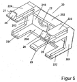
- Figure 5 shows the slide 20 having an end face 210, side walls 201 to 204 and guide elements 221 to 224.
- additional parts 25 to 28 of a locking device and a latch nose 29 are shown, the function of which will be described with reference to Figures 9 to 11 .
- Figure 6 shows the plug of the connector arrangement from Figure 4 in its unmated state wherein the slide 20 with its openings 21 and 22 are arranged in a starting position on the housing 10.
- Figure 8 shows a sectional drawing along a section 8-8 of Figure 7 illustrating how the slide 20 is held in the housing 10.
- the slide 20 is locked by a housing latch 14 and a part of the latch 25 designed as a projection in the housing 10.
- a mating plug for a connector arrangement with an associated plug according to Figure 6 is shown in Figure 9 .
- the mating plug 30 comprises a receiver 31 for an optical fiber and the optical fiber of the plug or its receiver, and a latch 32 and a projection 33.
- the mating plug can, in addition to the mating unit, not visible in Figure 9 , for the electrical contact unit of the plug from Figure 6 , be wider in design, in particular with respect to the receiver 31.
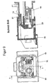
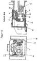
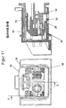
- Figures 10 to 15 show sectional drawings of a mating progression of the connector arrangement with the plug, consisting of the housing 10 and the slide 20, and the mating plug 30. The states shown in the figures are assumed during connection of the mating plug 30 to the plug.
- Figures 14 and 15 show the connector arrangement with plug and mating plug 30 in the mated state.
- the slide 20 is inserted into the housing 10 and the latch 29 is arranged in front of the projection 33.
- the projection 33 and the nose 32 return the slide 20 through the latch 29 into its starting position.
Landscapes
- Physics & Mathematics (AREA)
- General Physics & Mathematics (AREA)
- Optics & Photonics (AREA)
- Mechanical Coupling Of Light Guides (AREA)
- Optical Couplings Of Light Guides (AREA)
- Connector Housings Or Holding Contact Members (AREA)
- Cable Accessories (AREA)
Claims (9)
- Stecker für eine Steckverbinderanordnung, die aus einem Stecker und einem zugeordneten Gegenstecker (30) besteht, wobei der Stecker Folgendes umfasst:ein Gehäuse (10), das wenigstens eine axiale Aufnahme (11, 12) für einen Lichtwellenleiter hat,eine beweglich in dem Gehäuse (10) angebrachte Schutzvorrichtung zum Schützen des Lichtwellenleiters, wobei die Schutzvorrichtung ein Gleitstück (20) ist, das in Axialrichtung zu der Aufnahme (11, 12) bewegt werden kann und eine Öffnung (21, 22) für den Lichtwellenleiter und/oder die Aufnahme (11, 12) hat, wobei in einem herausgezogenen Zustand das Gleitstück (20) in einer Startstellung vor dem vorderen Ende der Aufnahme (11, 12) angeordnet ist und in einem eingesteckten Zustand das vordere Ende der Aufnahme (11, 12) durch die Öffnung (21, 22) hindurch vorsteht,eine Rückführungsvorrichtung, die das Gleitstück (20) auf ein Lösen des Gegensteckers (30) von dem Stecker hin in die Gleitstück-Startstellung zurückführt,dadurch gekennzeichnet, dass die Rückführungsvorrichtung eine Klinke (24, 29) umfasst, die als ein Teil des Gleitstücks (20) angeordnet ist und in dem eingesteckten Zustand vor einem entsprechend geformten Vorsprung (32, 33) an dem Gegenstecker (30) angeordnet ist, und dadurch, dass auf ein Trennen der Steckverbinderanordnung hin der Vorsprung (32, 33) das Gleitstück durch die Klinke (29) in seine Startstellung zurückführt.
- Stecker nach Anspruch 1, dadurch gekennzeichnet, dass die Bewegungsrichtung des Gleitstücks (20) einer Einsteckrichtung entspricht, in welcher der Stecker und der Gegenstecker (30) miteinander verbunden werden.
- Stecker nach einem der Ansprüche 1 oder 2, dadurch gekennzeichnet, dass das Gleitstück (20) als ein von dem Gehäuse (10) gesondertes Teil hergestellt wird, das in das Gehäuse (10) eingesetzt werden kann.
- Stecker nach einem der Ansprüche 1 bis 3, dadurch gekennzeichnet, dass das Gleitstück (20) in der Form einer Mulde gestaltet ist, mit einem vorderen Ende (210) und Seitenwänden (201 bis 204) und Führungselementen (221 bis 224), die sich von dem vorderen Ende (210) in der Richtung des Gehäuses (10) erstrecken.
- Stecker nach einem der Ansprüche 1 bis 4, dadurch gekennzeichnet, dass das Gehäuse (10) zwei oder mehr axiale Aufnahmen (11, 12) für mehrere Lichtwellenleiter umfasst, wobei jeweils ein Lichtwellenleiter in jeder Aufnahme (11, 12) angeordnet werden kann.
- Stecker nach einem der Ansprüche 1 bis 5, gekennzeichnet durch eine Arretierungsvorrichtung, welche die Bewegung des Gleitstücks (20) auf eine solche Weise einschränkt, dass die Startstellung des Gleitstücks (20) beibehalten wird, falls der Stecker nicht mit dem Gegenstecker (30) verbunden ist.
- Stecker nach Anspruch 6, dadurch gekennzeichnet, dass die Arretierungsvorrichtung auf eine Verbindung mit dem Gegenstecker (30) hin ausgerückt wird, um die Axialbewegung des Gleitstücks (20) freizugeben.
- Stecker nach Anspruch 6 oder 7, dadurch gekennzeichnet, dass die Arretierungsvorrichtung einen Arretierungsvorsprung (27) umfasst, der an einem Gehäusevorsprung (13, 15) anliegt, wobei die Vorsprünge (13, 15, 27) zueinander hin bewegt werden können, um die Arretierung auszurücken.
- Stecker nach einem der Ansprüche 6 bis 8, dadurch gekennzeichnet, dass die Arretierungsvorrichtung oder das Gehäuse (10) ein Teil (23, 27) enthalten, das sich schräg zu der Bewegungsrichtung des Gleitstücks (20) erstreckt und das die Bewegung des Gegensteckers (30) auf ein Verbinden hin in eine Bewegung zum Ausrücken der Arretierung umwandelt.
Applications Claiming Priority (2)
| Application Number | Priority Date | Filing Date | Title |
|---|---|---|---|
| DE10038685 | 2000-08-08 | ||
| DE10038685 | 2000-08-08 |
Publications (2)
| Publication Number | Publication Date |
|---|---|
| EP1180702A1 EP1180702A1 (de) | 2002-02-20 |
| EP1180702B1 true EP1180702B1 (de) | 2008-04-23 |
Family
ID=7651725
Family Applications (1)
| Application Number | Title | Priority Date | Filing Date |
|---|---|---|---|
| EP01118676A Expired - Lifetime EP1180702B1 (de) | 2000-08-08 | 2001-08-03 | Schutzvorrichtung an einem faseroptischen Steckverbinder |
Country Status (5)
| Country | Link |
|---|---|
| US (1) | US6913393B2 (de) |
| EP (1) | EP1180702B1 (de) |
| JP (1) | JP4756568B2 (de) |
| AT (1) | ATE393407T1 (de) |
| DE (1) | DE60133696T2 (de) |
Cited By (1)
| Publication number | Priority date | Publication date | Assignee | Title |
|---|---|---|---|---|
| EP2360802A1 (de) | 2010-02-22 | 2011-08-24 | Tyco Electronics Raychem BVBA | Schutzvorrichtung und Kabelabschlusseinheit |
Families Citing this family (9)
| Publication number | Priority date | Publication date | Assignee | Title |
|---|---|---|---|---|
| DE102004025512A1 (de) * | 2004-05-21 | 2005-12-15 | Neutrik Aktiengesellschaft | Einrichtung für eine optische Steckverbindung |
| US20060040564A1 (en) | 2004-08-19 | 2006-02-23 | Morrison David S | Block-out cover and removal tool |
| US7680384B2 (en) * | 2006-01-26 | 2010-03-16 | Corning Cable Systems Llc | Installation tool with integrated visual fault indicator for field-installable mechanical splice connector |
| US7993063B2 (en) * | 2009-03-16 | 2011-08-09 | Panduit Corp. | Block-out device for fiber optic adapter |
| WO2010125788A1 (ja) * | 2009-04-30 | 2010-11-04 | アダマンド工業株式会社 | 光コネクタプラグ |
| US8224146B2 (en) * | 2010-02-05 | 2012-07-17 | Panduit Corp. | Block-out device for fiber optic adapter |
| WO2013191563A1 (en) * | 2012-06-19 | 2013-12-27 | Knut Foseide | Protecting connector cover with attaching means |
| US11817667B1 (en) * | 2022-12-28 | 2023-11-14 | Rivian Ip Holdings, Llc | High voltage connector service extraction tool |
| DE102023130824A1 (de) * | 2023-11-07 | 2025-05-08 | Md Elektronik Gmbh | Steckverbinderanordnung mit zwei relativ zueinander verlagerbaren steckergehäuseteilen für einen zweistufigen steckvorgang |
Citations (1)
| Publication number | Priority date | Publication date | Assignee | Title |
|---|---|---|---|---|
| EP0339876A1 (de) * | 1988-04-25 | 1989-11-02 | The Whitaker Corporation | Steckeraufbau mit beweglicher Schutzverkleidung |
Family Cites Families (8)
| Publication number | Priority date | Publication date | Assignee | Title |
|---|---|---|---|---|
| US4084882A (en) * | 1976-08-30 | 1978-04-18 | International Telephone And Telegraph Corporation | Connector member |
| US4225214A (en) * | 1978-09-18 | 1980-09-30 | Trw Inc. | Connector construction |
| US5142598A (en) * | 1991-08-28 | 1992-08-25 | Porta Systems Corp. | Fiber optic connector having snap ring adjustment means |
| JP2797884B2 (ja) * | 1992-04-15 | 1998-09-17 | 住友電装株式会社 | 光ファイバコネクタ装置 |
| EP0613030B1 (de) | 1993-02-24 | 1998-02-04 | Sumitomo Wiring Systems, Ltd. | Optischer Stecker |
| US5506922A (en) * | 1994-08-01 | 1996-04-09 | Molex Incorporated | Fiber optic component assembly with a movable protective shield |
| US5896477A (en) * | 1997-05-16 | 1999-04-20 | Lucent Technologies Inc. | Optical fiber coupling buildout system |
| US6315461B1 (en) * | 1999-10-14 | 2001-11-13 | Ocean Design, Inc. | Wet mateable connector |
-
2001
- 2001-08-02 US US09/920,702 patent/US6913393B2/en not_active Expired - Lifetime
- 2001-08-03 DE DE60133696T patent/DE60133696T2/de not_active Expired - Lifetime
- 2001-08-03 EP EP01118676A patent/EP1180702B1/de not_active Expired - Lifetime
- 2001-08-03 AT AT01118676T patent/ATE393407T1/de not_active IP Right Cessation
- 2001-08-07 JP JP2001239277A patent/JP4756568B2/ja not_active Expired - Fee Related
Patent Citations (1)
| Publication number | Priority date | Publication date | Assignee | Title |
|---|---|---|---|---|
| EP0339876A1 (de) * | 1988-04-25 | 1989-11-02 | The Whitaker Corporation | Steckeraufbau mit beweglicher Schutzverkleidung |
Cited By (1)
| Publication number | Priority date | Publication date | Assignee | Title |
|---|---|---|---|---|
| EP2360802A1 (de) | 2010-02-22 | 2011-08-24 | Tyco Electronics Raychem BVBA | Schutzvorrichtung und Kabelabschlusseinheit |
Also Published As
| Publication number | Publication date |
|---|---|
| JP2002090577A (ja) | 2002-03-27 |
| DE60133696T2 (de) | 2009-07-09 |
| JP4756568B2 (ja) | 2011-08-24 |
| DE60133696D1 (de) | 2008-06-05 |
| US6913393B2 (en) | 2005-07-05 |
| EP1180702A1 (de) | 2002-02-20 |
| ATE393407T1 (de) | 2008-05-15 |
| US20040197053A1 (en) | 2004-10-07 |
Similar Documents
| Publication | Publication Date | Title |
|---|---|---|
| US6264374B1 (en) | Arrangement for integrating a rectangular fiber optic connector into a cylindrical connector | |
| US6357931B1 (en) | Hybrid connector | |
| US4840451A (en) | Shielded fiber optic connector assembly | |
| US5259052A (en) | High precision optical fiber connectors | |
| EP1237024B1 (de) | Buchse für optischen Stecker mit elektrischer Schaltfähigkeit | |
| EP0117022B1 (de) | Faseroptische Verbindungsanordnung | |
| EP1170609B1 (de) | Hybrider Steckverbinder und Verfahren zu seiner Herstellung | |
| EP1170612B1 (de) | Hybrider Steckverbinder für optische und elektrische Steckverbindungen | |
| EP0338727A2 (de) | Verbindervorrichtung mit Verriegelungsmechanismus | |
| EP1182478B1 (de) | Optischer Steckverbinder mit einer Kombination aus Führungszapfenverrieglung und Erdungskontakt | |
| US6926551B1 (en) | Pluggable transceiver latching mechanism | |
| SA02230335B1 (ar) | مهايئ adaptor شامل | |
| EP1180702B1 (de) | Schutzvorrichtung an einem faseroptischen Steckverbinder | |
| US9086546B2 (en) | Connector systems having receptacle assembly and plug assembly | |
| JP2004138707A (ja) | 光コネクタ | |
| JP3803073B2 (ja) | 光コネクタ | |
| JPH11512195A (ja) | 光ファイバーケーブル用プラグコネクタ | |
| US6206580B1 (en) | Optical connector | |
| US6457872B1 (en) | Optical waveguide plug connector for a mechanically releasable connection between at least one OWG connector pair and a mating connector | |
| US7488115B2 (en) | Fiber-optical plug as well as a single and double coupler for receiving such a plug | |
| US6364686B2 (en) | Electrical and/or optical connector with a latching arm | |
| CN117849953A (zh) | 包括主体和电缆套管的电气和/或光学触头以防止对容纳这种触头的连接、连接器或适配器的不希望的解锁 | |
| US20240151913A1 (en) | Electrical and/or optical contact comprising a body and a cable sleeve configured to prevent unwanted unlocking of a connection, connector or adaptor housing such a contact | |
| US12013584B2 (en) | High-speed active contact | |
| JP2001074978A (ja) | 光ファイバ接続コネクタ |
Legal Events
| Date | Code | Title | Description |
|---|---|---|---|
| PUAI | Public reference made under article 153(3) epc to a published international application that has entered the european phase |
Free format text: ORIGINAL CODE: 0009012 |
|
| AK | Designated contracting states |
Kind code of ref document: A1 Designated state(s): AT BE CH CY DE DK ES FI FR GB GR IE IT LI LU MC NL PT SE TR |
|
| AX | Request for extension of the european patent |
Free format text: AL;LT;LV;MK;RO;SI |
|
| 17P | Request for examination filed |
Effective date: 20020724 |
|
| AKX | Designation fees paid |
Free format text: AT BE CH CY DE DK ES FI FR GB GR IE IT LI LU MC NL PT SE TR |
|
| GRAC | Information related to communication of intention to grant a patent modified |
Free format text: ORIGINAL CODE: EPIDOSCIGR1 |
|
| GRAP | Despatch of communication of intention to grant a patent |
Free format text: ORIGINAL CODE: EPIDOSNIGR1 |
|
| RIN1 | Information on inventor provided before grant (corrected) |
Inventor name: BUCK, CARSTEN Inventor name: REIFEL, DIRK Inventor name: FERSTL, MICHAEL Inventor name: LOEFFELHOLZ, STEFAN |
|
| GRAS | Grant fee paid |
Free format text: ORIGINAL CODE: EPIDOSNIGR3 |
|
| GRAA | (expected) grant |
Free format text: ORIGINAL CODE: 0009210 |
|
| AK | Designated contracting states |
Kind code of ref document: B1 Designated state(s): AT BE CH CY DE DK ES FI FR GB GR IE IT LI LU MC NL PT SE TR |
|
| REG | Reference to a national code |
Ref country code: GB Ref legal event code: FG4D |
|
| REG | Reference to a national code |
Ref country code: CH Ref legal event code: EP |
|
| REF | Corresponds to: |
Ref document number: 60133696 Country of ref document: DE Date of ref document: 20080605 Kind code of ref document: P |
|
| REG | Reference to a national code |
Ref country code: IE Ref legal event code: FG4D Free format text: LANGUAGE OF EP DOCUMENT: FRENCH |
|
| NLV1 | Nl: lapsed or annulled due to failure to fulfill the requirements of art. 29p and 29m of the patents act | ||
| PG25 | Lapsed in a contracting state [announced via postgrant information from national office to epo] |
Ref country code: FI Free format text: LAPSE BECAUSE OF FAILURE TO SUBMIT A TRANSLATION OF THE DESCRIPTION OR TO PAY THE FEE WITHIN THE PRESCRIBED TIME-LIMIT Effective date: 20080423 Ref country code: NL Free format text: LAPSE BECAUSE OF FAILURE TO SUBMIT A TRANSLATION OF THE DESCRIPTION OR TO PAY THE FEE WITHIN THE PRESCRIBED TIME-LIMIT Effective date: 20080423 Ref country code: ES Free format text: LAPSE BECAUSE OF FAILURE TO SUBMIT A TRANSLATION OF THE DESCRIPTION OR TO PAY THE FEE WITHIN THE PRESCRIBED TIME-LIMIT Effective date: 20080803 Ref country code: PT Free format text: LAPSE BECAUSE OF FAILURE TO SUBMIT A TRANSLATION OF THE DESCRIPTION OR TO PAY THE FEE WITHIN THE PRESCRIBED TIME-LIMIT Effective date: 20080923 |
|
| PG25 | Lapsed in a contracting state [announced via postgrant information from national office to epo] |
Ref country code: AT Free format text: LAPSE BECAUSE OF FAILURE TO SUBMIT A TRANSLATION OF THE DESCRIPTION OR TO PAY THE FEE WITHIN THE PRESCRIBED TIME-LIMIT Effective date: 20080423 |
|
| PG25 | Lapsed in a contracting state [announced via postgrant information from national office to epo] |
Ref country code: DK Free format text: LAPSE BECAUSE OF FAILURE TO SUBMIT A TRANSLATION OF THE DESCRIPTION OR TO PAY THE FEE WITHIN THE PRESCRIBED TIME-LIMIT Effective date: 20080423 Ref country code: SE Free format text: LAPSE BECAUSE OF FAILURE TO SUBMIT A TRANSLATION OF THE DESCRIPTION OR TO PAY THE FEE WITHIN THE PRESCRIBED TIME-LIMIT Effective date: 20080723 |
|
| ET | Fr: translation filed | ||
| PG25 | Lapsed in a contracting state [announced via postgrant information from national office to epo] |
Ref country code: BE Free format text: LAPSE BECAUSE OF FAILURE TO SUBMIT A TRANSLATION OF THE DESCRIPTION OR TO PAY THE FEE WITHIN THE PRESCRIBED TIME-LIMIT Effective date: 20080423 |
|
| PLBE | No opposition filed within time limit |
Free format text: ORIGINAL CODE: 0009261 |
|
| STAA | Information on the status of an ep patent application or granted ep patent |
Free format text: STATUS: NO OPPOSITION FILED WITHIN TIME LIMIT |
|
| PG25 | Lapsed in a contracting state [announced via postgrant information from national office to epo] |
Ref country code: MC Free format text: LAPSE BECAUSE OF NON-PAYMENT OF DUE FEES Effective date: 20080831 |
|
| REG | Reference to a national code |
Ref country code: CH Ref legal event code: PL |
|
| 26N | No opposition filed |
Effective date: 20090126 |
|
| PG25 | Lapsed in a contracting state [announced via postgrant information from national office to epo] |
Ref country code: LI Free format text: LAPSE BECAUSE OF NON-PAYMENT OF DUE FEES Effective date: 20080831 Ref country code: CH Free format text: LAPSE BECAUSE OF NON-PAYMENT OF DUE FEES Effective date: 20080831 |
|
| PG25 | Lapsed in a contracting state [announced via postgrant information from national office to epo] |
Ref country code: IE Free format text: LAPSE BECAUSE OF NON-PAYMENT OF DUE FEES Effective date: 20080803 |
|
| PG25 | Lapsed in a contracting state [announced via postgrant information from national office to epo] |
Ref country code: LU Free format text: LAPSE BECAUSE OF NON-PAYMENT OF DUE FEES Effective date: 20080803 Ref country code: CY Free format text: LAPSE BECAUSE OF FAILURE TO SUBMIT A TRANSLATION OF THE DESCRIPTION OR TO PAY THE FEE WITHIN THE PRESCRIBED TIME-LIMIT Effective date: 20080423 |
|
| PG25 | Lapsed in a contracting state [announced via postgrant information from national office to epo] |
Ref country code: TR Free format text: LAPSE BECAUSE OF FAILURE TO SUBMIT A TRANSLATION OF THE DESCRIPTION OR TO PAY THE FEE WITHIN THE PRESCRIBED TIME-LIMIT Effective date: 20080423 |
|
| PG25 | Lapsed in a contracting state [announced via postgrant information from national office to epo] |
Ref country code: GR Free format text: LAPSE BECAUSE OF FAILURE TO SUBMIT A TRANSLATION OF THE DESCRIPTION OR TO PAY THE FEE WITHIN THE PRESCRIBED TIME-LIMIT Effective date: 20080724 |
|
| REG | Reference to a national code |
Ref country code: DE Ref legal event code: R082 Ref document number: 60133696 Country of ref document: DE Representative=s name: MARKS & CLERK (LUXEMBOURG) LLP, LU Ref country code: DE Ref legal event code: R081 Ref document number: 60133696 Country of ref document: DE Owner name: TE CONNECTIVITY GERMANY GMBH, DE Free format text: FORMER OWNER: TYCO ELECTRONICS AMP GMBH, 64625 BENSHEIM, DE |
|
| REG | Reference to a national code |
Ref country code: FR Ref legal event code: PLFP Year of fee payment: 15 |
|
| REG | Reference to a national code |
Ref country code: FR Ref legal event code: CD Owner name: TE CONNECTIVITY GERMANY GMBH Effective date: 20151027 |
|
| REG | Reference to a national code |
Ref country code: FR Ref legal event code: PLFP Year of fee payment: 16 |
|
| REG | Reference to a national code |
Ref country code: FR Ref legal event code: PLFP Year of fee payment: 17 |
|
| REG | Reference to a national code |
Ref country code: FR Ref legal event code: PLFP Year of fee payment: 18 |
|
| PGFP | Annual fee paid to national office [announced via postgrant information from national office to epo] |
Ref country code: FR Payment date: 20180612 Year of fee payment: 18 |
|
| PGFP | Annual fee paid to national office [announced via postgrant information from national office to epo] |
Ref country code: IT Payment date: 20180823 Year of fee payment: 18 |
|
| PGFP | Annual fee paid to national office [announced via postgrant information from national office to epo] |
Ref country code: GB Payment date: 20180801 Year of fee payment: 18 |
|
| GBPC | Gb: european patent ceased through non-payment of renewal fee |
Effective date: 20190803 |
|
| PG25 | Lapsed in a contracting state [announced via postgrant information from national office to epo] |
Ref country code: FR Free format text: LAPSE BECAUSE OF NON-PAYMENT OF DUE FEES Effective date: 20190831 |
|
| PG25 | Lapsed in a contracting state [announced via postgrant information from national office to epo] |
Ref country code: IT Free format text: LAPSE BECAUSE OF NON-PAYMENT OF DUE FEES Effective date: 20190803 Ref country code: GB Free format text: LAPSE BECAUSE OF NON-PAYMENT OF DUE FEES Effective date: 20190803 |
|
| PGFP | Annual fee paid to national office [announced via postgrant information from national office to epo] |
Ref country code: DE Payment date: 20200722 Year of fee payment: 20 |
|
| REG | Reference to a national code |
Ref country code: DE Ref legal event code: R071 Ref document number: 60133696 Country of ref document: DE |