EP1180830A2 - Prise fixée sur un plafond ou un mur pour appareils électriques - Google Patents
Prise fixée sur un plafond ou un mur pour appareils électriques Download PDFInfo
- Publication number
- EP1180830A2 EP1180830A2 EP01810732A EP01810732A EP1180830A2 EP 1180830 A2 EP1180830 A2 EP 1180830A2 EP 01810732 A EP01810732 A EP 01810732A EP 01810732 A EP01810732 A EP 01810732A EP 1180830 A2 EP1180830 A2 EP 1180830A2
- Authority
- EP
- European Patent Office
- Prior art keywords
- wall
- ceiling
- fixing ring
- ceiling connection
- connection according
- Prior art date
- Legal status (The legal status is an assumption and is not a legal conclusion. Google has not performed a legal analysis and makes no representation as to the accuracy of the status listed.)
- Withdrawn
Links
Images
Classifications
-
- F—MECHANICAL ENGINEERING; LIGHTING; HEATING; WEAPONS; BLASTING
- F21—LIGHTING
- F21V—FUNCTIONAL FEATURES OR DETAILS OF LIGHTING DEVICES OR SYSTEMS THEREOF; STRUCTURAL COMBINATIONS OF LIGHTING DEVICES WITH OTHER ARTICLES, NOT OTHERWISE PROVIDED FOR
- F21V21/00—Supporting, suspending, or attaching arrangements for lighting devices; Hand grips
- F21V21/02—Wall, ceiling, or floor bases; Fixing pendants or arms to the bases
- F21V21/03—Ceiling bases, e.g. ceiling roses
-
- H—ELECTRICITY
- H01—ELECTRIC ELEMENTS
- H01R—ELECTRICALLY-CONDUCTIVE CONNECTIONS; STRUCTURAL ASSOCIATIONS OF A PLURALITY OF MUTUALLY-INSULATED ELECTRICAL CONNECTING ELEMENTS; COUPLING DEVICES; CURRENT COLLECTORS
- H01R13/00—Details of coupling devices of the kinds covered by groups H01R12/70 or H01R24/00 - H01R33/00
- H01R13/73—Means for mounting coupling parts to apparatus or structures, e.g. to a wall
-
- H—ELECTRICITY
- H02—GENERATION; CONVERSION OR DISTRIBUTION OF ELECTRIC POWER
- H02G—INSTALLATION OF ELECTRIC CABLES OR LINES, OR OF COMBINED OPTICAL AND ELECTRIC CABLES OR LINES
- H02G3/00—Installations of electric cables or lines or protective tubing therefor in or on buildings, equivalent structures or vehicles
- H02G3/02—Details
- H02G3/08—Distribution boxes; Connection or junction boxes
- H02G3/18—Distribution boxes; Connection or junction boxes providing line outlets
- H02G3/20—Ceiling roses or other lighting sets
-
- H—ELECTRICITY
- H01—ELECTRIC ELEMENTS
- H01R—ELECTRICALLY-CONDUCTIVE CONNECTIONS; STRUCTURAL ASSOCIATIONS OF A PLURALITY OF MUTUALLY-INSULATED ELECTRICAL CONNECTING ELEMENTS; COUPLING DEVICES; CURRENT COLLECTORS
- H01R2103/00—Two poles
-
- H—ELECTRICITY
- H01—ELECTRIC ELEMENTS
- H01R—ELECTRICALLY-CONDUCTIVE CONNECTIONS; STRUCTURAL ASSOCIATIONS OF A PLURALITY OF MUTUALLY-INSULATED ELECTRICAL CONNECTING ELEMENTS; COUPLING DEVICES; CURRENT COLLECTORS
- H01R24/00—Two-part coupling devices, or either of their cooperating parts, characterised by their overall structure
- H01R24/76—Two-part coupling devices, or either of their cooperating parts, characterised by their overall structure with sockets, clips or analogous contacts and secured to apparatus or structure, e.g. to a wall
Definitions
- the invention relates to a wall and ceiling connection for electrical consumers according to the preamble of the independent claim
- the object of the invention is to provide a wall and ceiling connection for electrical Specify consumer in which a once created installation in the wall or Cover may remain if the consumer is changed or removed.
- An additional advantage of the invention is that the electrical connection via Standard plug can be made. This can be on the electrical consumer in the de-energized Condition pre-assembled. There is a risk of contact with live lines thereby avoided.
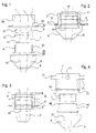
- a ceiling closure according to the invention for electrical consumers is under construction Figures 1 and 4 clearly visible. It has a bracket for attachment in a Recess in a wall or ceiling D. First electrical conductors 111, 112 are as Cable is drawn into the wall or ceiling and leads into the recess.
- the Bracket consists of a mounting body M, a sleeve bracket 1.
- a fixing ring 4 can be partially screwed into the mounting body M from below.
- the mounting body M has an internal thread 23, 73 over part of its length.
- the fixing ring 4 has one suitable external thread 43.
- the socket holder 1 has an external diameter, which corresponds to the inside diameter of the fixing ring 4. With a paragraph 12 the sleeve holder 1 comes to a stop at the upper end of the fixing ring 4.
- Paragraph 12 is a circumferential ring or designed as outwardly projecting tabs. Your outside diameter is larger than the inside diameter of the fixing ring 4 and smaller than the inside diameter of the Assembly body M.
- the sleeve holder is provided with means for connecting first electrical conductors 111, 112 as supply line, with second electrical conductors 611, 612 for connecting one Provided to the consumer.
- the arrangement of the sleeves 11 in the sleeve holder 1 corresponds to that of a standard socket. It can be seen that instead of a device also an ordinary standard plug 8 in the socket holder 1 of the wall and Ceiling connector can be inserted ( Figure 3). The consumer can thus from Wall and ceiling connection itself must be removed.
- the mounting body can either as a mounting ring 2 ( Figures 1 to 3) or as Mounting box 7 ( Figure 4) can be executed.
- the conductors 111, 112 are pulled through the assembly ring 2.
- the Mounting ring 2 is then inserted into the recess in the wall or ceiling until it abuts with a ceiling finish 22 on the underside of the wall or ceiling.
- a snap ring is pulled on and the conductors 111, 112 are in sleeves 11 in the Socket holder attached in the usual way.
- the sleeve holder 11 corresponds in the Arrangement of the sleeves the usual standard sockets. So can be used as a consumer connection a normal standard plug can also be used.
- a fixing ring 4 is placed from below over the socket holder 1 and everything screwed together upwards into the mounting ring.
- the fixing ring 4 External thread 43, which corresponds to an internal thread 23 in the mounting ring 2.
- the snap ring 3 has one outwardly inclined surface as conical extension 31.
- the conical extension 31 now comes to a conical constriction 21 in the interior of the mounting ring 2 Issue.
- the mounting ring 2 is clamped on the side of the recess on the wall or blanket tight.
- a rotary stop with groove and cam can ensure that the Do not screw in the fixing ring 4 the sleeve holder 1 relative to the mounting ring 2 can be twisted.
- the fixing ring 4 at the top with a retracted stop paragraph 46 may be provided, in which the sleeve holder 1 with your paragraph 12 comes to mind ( Figure 4).
- the sleeve holder 12 can thus Fixing ring can be rotated.
- a consumer connection is then connected.
- a cover 5 which can simultaneously be a suspension for a consumer (lamp holder, etc.) has a plug insert 6. It is rotatably arranged therein.
- the connector elements 611, 612 are pushed into the sleeves 11 and retracted.
- the first Tabs 45 radially outwards and at the top of the cover have second tabs 55 radially inwards.
- the first tabs 45 can also be arranged radially inwards and the second tabs 55 point radially outwards.
- the cover is from the bottom the fixing ring 4 created, pushed slightly upwards and at a certain angle twisted. Now the second tabs 55 of the cover 5 engage behind the first tabs 45 of the fixing ring 4. It is obvious that either the socket holder 1 or the plug insert 6 are rotatable in their receptacle, so that the plug connection comes about and the wall or ceiling connection can be closed.
- assembly boxes 7 be worked according to Figure 4.
- Such mounting boxes 7 have lateral Cable entries on.
- the mounting box 7 has an internal thread leading from bottom to top 73, which corresponds to the internal thread 23 in the mounting ring 2.
- Sleeve holder 1, Cover 5 with rotatable plug insert 6 and fixing ring 4 are identical to that Execution described above.
- the mounting box 7 now points in the lower area End a snap groove 72 and / or a thread protector.
- the ceiling Before concreting a wall or In addition to the reinforcements, the ceiling also includes cable ducts, junction boxes and just that such assembly boxes brought forward.
- the mounting box 7 is simply at the desired location placed on a formwork. Then it is attached to it by mounting plate 75 or the assembly box 7 is nailed, screwed or glued to the formwork. If the ceiling material has hardened and the formwork is removed, so it snaps Mounting plate 75 from the snap groove 72 and remains on the formwork. Of course it can Mounting box 7 can also be attached directly to the formwork. It is recommended to insert a thread protector into the assembly box 7 so that no concrete or the like can penetrate during construction. Poured into the wall or ceiling there remains the mounting box 7. It is now ready to pull in cables with conductors 111, 112. The wall and ceiling connection can then be finished as described above to be assembled.
Landscapes
- Engineering & Computer Science (AREA)
- General Engineering & Computer Science (AREA)
- Architecture (AREA)
- Civil Engineering (AREA)
- Structural Engineering (AREA)
- Connector Housings Or Holding Contact Members (AREA)
- Fastening Of Light Sources Or Lamp Holders (AREA)
- Connecting Device With Holders (AREA)
Applications Claiming Priority (2)
| Application Number | Priority Date | Filing Date | Title |
|---|---|---|---|
| CH15902000 | 2000-08-17 | ||
| CH159000 | 2000-08-17 |
Publications (2)
| Publication Number | Publication Date |
|---|---|
| EP1180830A2 true EP1180830A2 (fr) | 2002-02-20 |
| EP1180830A3 EP1180830A3 (fr) | 2003-10-22 |
Family
ID=4565578
Family Applications (1)
| Application Number | Title | Priority Date | Filing Date |
|---|---|---|---|
| EP01810732A Withdrawn EP1180830A3 (fr) | 2000-08-17 | 2001-07-25 | Prise fixée sur un plafond ou un mur pour appareils électriques |
Country Status (1)
| Country | Link |
|---|---|
| EP (1) | EP1180830A3 (fr) |
Cited By (4)
| Publication number | Priority date | Publication date | Assignee | Title |
|---|---|---|---|---|
| GB2446430A (en) * | 2007-02-09 | 2008-08-13 | Contactum Ltd | Fitting for mounting electrical components in a surface |
| EP2696457A3 (fr) * | 2012-08-06 | 2014-03-26 | Peter Dokulil | Système de coffrage pour une lampe intégrée dans un mur en béton, lampe intégrée dans un mur en béton et procédé de configuration d'un espace creux dans un mur en béton pour loger une lampe |
| CN104359057A (zh) * | 2014-10-28 | 2015-02-18 | 立达信绿色照明股份有限公司 | 快装吸顶灯 |
| CN106402722A (zh) * | 2015-07-30 | 2017-02-15 | 潘忠勋 | 用于大功率led灯的插入式驱动电源装置 |
Family Cites Families (6)
| Publication number | Priority date | Publication date | Assignee | Title |
|---|---|---|---|---|
| US447832A (en) * | 1891-03-10 | Half to the craighead | ||
| US1351150A (en) * | 1919-04-11 | 1920-08-31 | Battle Richard | Device for attaching electric-light fixtures to outlet-boxes |
| GB409180A (en) * | 1933-08-05 | 1934-04-26 | Samuel Kelso | Improvements in electrical fixture supporting and connecting devices |
| DE2526762A1 (de) * | 1975-06-14 | 1976-12-16 | Helmut Sterzenbach | Aufhaengevorrichtung fuer ein elektrisches geraet |
| DE19702395A1 (de) * | 1997-01-24 | 1998-07-30 | Walter Schneider | Vorrichtung zum Aufhängen einer elektrisch betriebenen Lampe |
| EP0895023A3 (fr) * | 1997-07-31 | 2000-12-27 | Stucki Elektroberatung | Dispositif de montage d' une lampe à un plafond ou à un mur |
-
2001
- 2001-07-25 EP EP01810732A patent/EP1180830A3/fr not_active Withdrawn
Cited By (5)
| Publication number | Priority date | Publication date | Assignee | Title |
|---|---|---|---|---|
| GB2446430A (en) * | 2007-02-09 | 2008-08-13 | Contactum Ltd | Fitting for mounting electrical components in a surface |
| GB2446430B (en) * | 2007-02-09 | 2012-03-07 | Savvy Switches Ltd | Universal fitting for mounting components |
| EP2696457A3 (fr) * | 2012-08-06 | 2014-03-26 | Peter Dokulil | Système de coffrage pour une lampe intégrée dans un mur en béton, lampe intégrée dans un mur en béton et procédé de configuration d'un espace creux dans un mur en béton pour loger une lampe |
| CN104359057A (zh) * | 2014-10-28 | 2015-02-18 | 立达信绿色照明股份有限公司 | 快装吸顶灯 |
| CN106402722A (zh) * | 2015-07-30 | 2017-02-15 | 潘忠勋 | 用于大功率led灯的插入式驱动电源装置 |
Also Published As
| Publication number | Publication date |
|---|---|
| EP1180830A3 (fr) | 2003-10-22 |
Similar Documents
| Publication | Publication Date | Title |
|---|---|---|
| EP3052710B1 (fr) | Plaque de montage pour corps de wc | |
| EP2059718B1 (fr) | Dispositif de raccord pour des lampes | |
| DE2647043C2 (de) | Zugentlastungsvorrichtung für eine Kabeleinführung in ein Gehäuse eines elektrischen Gerätes | |
| DE60004333T2 (de) | Elektrischer verbinder mit schneidklemmschraube | |
| EP0917276B1 (fr) | Carcasse pour moteur électrique | |
| EP2226430B1 (fr) | Dispositif de raccordement pour armatures d'écoulement | |
| DE3817100A1 (de) | Unterputzdose fuer insbesondere mauerwerks- und hohlwandmontage | |
| DE10012157C1 (de) | Tülle | |
| DE2730859A1 (de) | Vorrichtung zum aufhaengen von wand- oder deckenleuchten | |
| DE10322177A1 (de) | LED-Einbauleuchte | |
| DE602005004621T2 (de) | Messsensor | |
| DE20204323U1 (de) | Einsetzvorrichtung mit synchronem, leitfähigem Draht für eine Lampenstange und eine Drahtverbindung | |
| CH711488A1 (de) | Einbaubüchsendeckel zum Verschliessen einer Öffnung in einer Einbaubüchse. | |
| DE3636574C2 (de) | Wasserdichtes Gehäuse, insbesondere für die Verkapselung elektrischer und elektronischer Bauteile | |
| DE4334067C2 (de) | Niedervoltinstallationssystem | |
| DE10035383C2 (de) | Verriegelbare Anschlussdose für einen gesteckten Anschlussstecker | |
| DE202006020030U1 (de) | Anschlussvorrichtung für Leuchten | |
| DE202015001170U1 (de) | System für das Anschließen eines elektrischen Moduls | |
| DE9203261U1 (de) | Koaxialkabelstecker/-kupplung | |
| DE29719000U1 (de) | Kabelverbinder und damit ausgerüstete Abzweigdose | |
| CH681237A5 (fr) | ||
| DE2837328A1 (de) | Halterung fuer elektrische geraete | |
| DE2833565A1 (de) | Werkzeug als montagehilfe zum anschliessen eines koaxialkabels an einen koaxialsteckverbinder und umgekehrt als demontagehilfe | |
| DE102024203521A1 (de) | Befestigungseinrichtung, Verwendung, Kraftfahrzeug und Verfahren | |
| CH384671A (de) | Bodenanschlussvorrichtung für elektrische Unterflur-Installationen |
Legal Events
| Date | Code | Title | Description |
|---|---|---|---|
| PUAI | Public reference made under article 153(3) epc to a published international application that has entered the european phase |
Free format text: ORIGINAL CODE: 0009012 |
|
| AK | Designated contracting states |
Kind code of ref document: A2 Designated state(s): AT BE CH CY DE DK ES FI FR GB GR IE IT LI LU MC NL PT SE TR |
|
| AX | Request for extension of the european patent |
Free format text: AL;LT;LV;MK;RO;SI |
|
| PUAL | Search report despatched |
Free format text: ORIGINAL CODE: 0009013 |
|
| AK | Designated contracting states |
Kind code of ref document: A3 Designated state(s): AT BE CH CY DE DK ES FI FR GB GR IE IT LI LU MC NL PT SE TR |
|
| AX | Request for extension of the european patent |
Extension state: AL LT LV MK RO SI |
|
| RIC1 | Information provided on ipc code assigned before grant |
Ipc: 7H 01R 13/639 B Ipc: 7F 21V 21/03 B Ipc: 7H 02G 3/20 B Ipc: 7H 01R 13/73 A |
|
| AKX | Designation fees paid | ||
| REG | Reference to a national code |
Ref country code: DE Ref legal event code: 8566 |
|
| STAA | Information on the status of an ep patent application or granted ep patent |
Free format text: STATUS: THE APPLICATION IS DEEMED TO BE WITHDRAWN |
|
| 18D | Application deemed to be withdrawn |
Effective date: 20040423 |